Applied Parameters: Mode=Polygonal_Room
Summary
This command is used to place a polygonal room onto the current document. A room is a primitive design object. It is a region that assists in the placement of components. The room can either be placed empty and components associated at a later stage, or it can be placed around components in the design, automatically associating them to the room.
For detailed information about this object type, see
Room.
Access
This command can be accessed from the PCB Editor by:
- Choosing the Design » Rooms » Place Polygonal Room command, from the main menus.
- Clicking the
 button on the Place Room drop-down (
 ) of the Utilities toolbar.
Use
After launching the command, the cursor will change to a cross-hair and you will enter room placement mode. Placement is made by performing the following sequence of actions:
- Position the cursor and click, or press Enter, to anchor the starting vertex for the room.
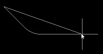
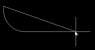
- Move the cursor ready to place the second vertex. The default behavior is to place 2 edges with each click, with a user-defined corner shape between them. Refer to the Placement Modes section below for more details on changing corner modes.
- Continue to move the mouse and click, or press Enter, to place further vertices.
- After placing the final vertex, right-click, or press Esc, to close and complete placement of the room. There is no need to manually close the polygon as the software will automatically complete the shape by connecting the start point to the final point placed
- Continue placing further polygonal rooms, or right-click, or press Esc, to exit placement mode.
Press the
Tab key during placement to access the
Edit Room Definition dialog, from where you can change properties for the room's associated
Room Definition Rule on-the-fly.
Placement Modes
- While placing a polygon there are 5 available corner modes, 4 of which also have corner direction sub-modes. During placement:
- Press Shift+Spacebar to cycle through the 5 available corner modes: 45 degree, 45 degree with arc, 90 degree, 90 degree with arc, and Any Angle.
- Press Spacebar to toggle between the two corner direction sub-modes.
- When in either of the arc corner modes, hold the
 or
or  keys to shrink or grow the arc. Hold the Shift key as you press to accelerate arc resizing.
- Press the 1 shortcut key to toggle between placing two edges per click, or one edge per click. In this second mode the dashed edge is referred to as the look-ahead segment (as shown in the last image in the set below).
- Press the Backspace key to remove the last vertex.


Press Shift+Spacebar to cycle through the 5 available corner modes, press the 1 shortcut to toggle placement between
2 edges or 1 edge.
Auto-Component Association
By placing a polygonal room around one or more components, so that they fall completely within its boundaries, the components will automatically be associated to the room. The scope or query created for the room's definition rule, depends on whether all components are part of an existing component class or not. If they are, then this component class will be used. If not, a new component class is created, with these components as its members. It is therefore possible to have multiple rooms, each with a scope that targets a particular component class, and have one or more mutual component members between those classes.
Manual Component Association
When an empty polygonal room is placed in the design, components required to be placed in the room should be grouped together by the use of a specific component class. A Room Definition rule will automatically be created and assigned to the room, with an initial scope (Full Query) of All. Edit this query to target the specific component class previously defined. The components can then be moved to the room by the use of the Arrange Within Room command.
Tips
- A Room Definition design rule is created for each room that is placed. Double-click on a placed room to open the Edit Room Definition dialog, in order to edit its rule properties. Alternatively, use the PCB Rules and Constraints Editor dialog to gain access to a particular room definition.
- Once component(s) have been assigned to a room they move when the room is moved. To move a room without moving the components, temporarily disable the associated Room Definition rule in the PCB Rules and Constraints Editor dialog.
- A room can also be locked to prevent accidentally moving it. To lock a room, double-click on it and enable the Room Locked option in the Edit Room Definition dialog.
- As well as being a design rule in its own right (Room Definition), a room can also be used as an object when defining the scope of another rule, such as Clearance or Height. As the room is to be used as an object rather than a rule, you can disable the rule. The following two queries can be used when using a room object in another rules' scope definition:
- TouchesRoom(RoomName) - use to find objects that are completely or partially within the room.
- WithinRoom(RoomName) - use to find objects that are completely within the room.
