Applied Parameters: None
Summary
This command is used to place a Polygon Pour object onto the active document. Polygon pours are used to create a solid or hatched (lattice) area on a PCB layer. Also referred to as copper pours, polygon pours are used to fill irregularly shaped areas of a board, automatically pouring around existing objects, connecting only to objects on the same net as the polygon pour. A polygon pour is a group design object - that is, it is made up of simpler primitive objects, either regions, or tracks and arcs.
On a signal layer, you can place a solid polygon pour to define an area for carrying large power supply currents, or as a ground-connected area for providing electro-magnetic shielding. Hatched polygon pours are commonly used for ground purposes in analog designs.
For detailed information about this object type, see
Polygon Pour.
Access
This command can be accessed from the PCB Editor by:
- Choosing the Place » Polygon Pour command, from the main menus.
- Clicking the
 button, on the Wiring toolbar.
Use
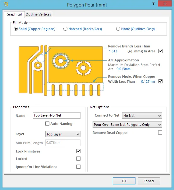
After launching the command, the Polygon Pour dialog will open:

Define the properties of the Polygon before placing it.
- Select the polygon Fill Mode, these are discussed in more detail below.
- Select the required net in the Connect to Net drop down.
- Note that each polygon has a Name, a system-defined name will be based on the layer and the net, enter your preferred Name. Alternatively, enable the Auto Naming option to have automatic polygon naming applied to the polygon. Naming is based on the chosen naming template, specified using the Polygon Auto Naming Template field, in the Board Options dialog (Design » Board Options). The name is based on the layer, the connected net, and a unique numerical index.
- Typically that is all that needs to be set before placement - click OK to commence defining the polygon shape.
- Position the cursor and click to anchor the starting vertex for the polygon.
- Move the cursor ready to place the second vertex. The default behavior is to place 2 edges with each click, with a user-defined corner shape between them. Refer to the Placement Modes section below for more details on changing corner modes.
- Continue to move the mouse and click to place further vertices.
- After placing the final vertex, right-click or press Esc to close and complete placement of the polygon. There is no need to manually close the polygon as the software will automatically complete the shape by connecting the start point to the final point placed.
The Polygon Pour dialog can be accessed again at any time during placement, by pressing the Tab key.
While attributes can be modified during placement (through the associated properties dialog), bear in mind that these will become the default settings for further placement unless the Permanent option on the PCB Editor – Defaults page of the Preferences dialog is enabled. When this option is enabled, changes made will affect only the object being placed and subsequent objects placed during the same placement session.
Placement Modes
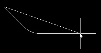
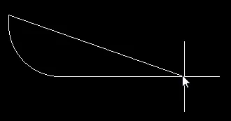
- While placing a polygon there are 5 available corner modes, 4 of which also have corner direction sub-modes. During placement:
- Press Shift+Spacebar to cycle through the 5 available corner modes: 45 degree, 45 degree with arc, 90 degree, 90 degree with arc, and Any Angle.
- Press Spacebar to toggle between the two corner direction sub-modes.
- When in either of the arc corner modes, hold the
 or
or  keys to shrink or grow the arc. Hold the Shift key as you press to accelerate arc resizing.
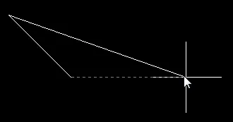
- Press the 1 shortcut key to toggle between placing two edges per click, or one edge per click. In this second mode the dashed edge is referred to as the look-ahead segment (as shown in the last image in the set below).
- Press the Backspace key to remove the last vertex.


Press Shift+Spacebar to cycle through the 5 available corner modes, press the 1 shortcut to toggle placement between
2 edges or 1 edge.
Polygon Fill Modes
The polygon pour placement engine can construct polygons from either solid regions, or from a combination of tracks and arcs. To help you decide which of these to use, consider the following:
- Region based polygons result in far fewer objects being placed, making for: smaller files; faster redraws, file opening, DRC and net connectivity analysis; and smaller output files as the region object is fully supported in Gerber and ODB++.
- Track/Arc based polygons allow a hatched polygon to be created, by setting the Track Width to be smaller than the Grid Size. Note that they can also be solid by setting the Track Width to be larger than the Grid Size.
- Outline Only polygons are simply Track/Arc polygons without the internal tracks and arcs.


The same Polygon, poured using regions, then poured using tracks/arcs.
Tips
- Auto-assigned names are continually monitored and managed by the software. If an attribute changes, such as the net assignment or the position of the layer in the layer stack, then the auto-assigned name is automatically updated. Affected design rules are also automatically updated.
- As well as interactively placing a polygon, it can also be created from a set of existing track and arc objects that define a closed shape. To define a polygon from an existing closed shape, simply select all primitives that form the closed shape, then choose the Tools » Convert » Create Polygon from Selected Primitives command, from the main menus.
- A new polygon pour can also be created from an existing polygon pour, or from the board outline, using the Polygon Pour Manager dialog.
- A polygon pour can be converted to its constituent primitive objects using the Tools » Convert » Explode Polygon to Free Primitives command. Solid polygons will revert to region primitives, while hatched polygons will revert to tracks and arcs. Once exploded, a polygon pour object can no longer be manipulated as a group object.
