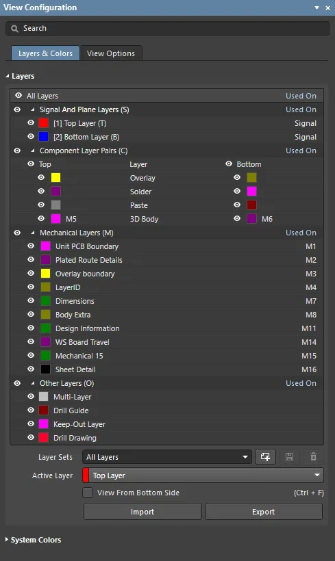
- Signal and Plane Layers – click the color button to change that layer's color, as described previously in the Displaying or Hiding a Layer section. Click the visibility icon (
 ) to toggle the display of an individual signal or plane layer. Signal and Plane layers are added, named and removed in the Pad-Via Layer Editor.
- Component Layer Pairs – these layers are paired so that when a component is flipped from the top side to the bottom side of the board (L shortcut as a component is being moved), the software can flip the top side layer contents onto their paired bottom side layers. User-defined component layer pairs can be defined using Mechanical layers.
- Mechanical Layers – these are general purpose drawing layers. These layers can also be paired and when paired, they become a Component Layer Pair. Component Layer Pairs are used for special-purpose roles, for example glue dots, or 3D component bodies. To rename a mechanical layer, right-click on it to open the Edit Layer dialog from the context menu.
- Other Layers – these are system managed layers, for example, objects placed on the multi-layer automatically appear on all signal layers, and objects placed on the keepout layer act as a keep-clear boundary on all signal layers.
- Layers Sets - use the drop-down to select an existing Layer Set. The following buttons are used to create, save, and delete Layer Sets:
-
 - click to create a new Layer Set. The set will appear as My Layers in the drop-down. Each subsequent Layer Set added will be numbered.
-
 - click to save when you create a new Layer Set or if you have edited the currently selected Layer Set. The creating and renaming of a Layer Set do not require a save action, as those functions save automatically. Changing the configuration of enabled layers, including your own Layer Set, does require a save action.
-
 - click to delete the currently selected Layer Set.
- Active Layers - use the drop-down to view one of the various Active Layers on the PCB individually.
- View From Bottom Side - check this box to view the Layer Sets from the bottom side.
- Import - click this to import the desired PCB Layer Set File (*.layerset).
- Export - click this to export the desired Layer Set as a PCB Layer Set File (*.layerset).
Refer to
The Board page to learn more about the layers in a printed circuit board.
Refer to the
Defining the Layer Stack page to learn how to configure the layer stack.
To configure and edit a pair of mechanical layers as a Component Layer Pair:
1. Right-click anywhere in the Layers region of the Layers & Colors tab, then select Layer Stack Manager to open the Layer Stack Manager. Here, you can assign a name or comment to a Layer, add Stack Symmetry and Library Compliance for a board, and view the number of Layers, Dielectrics, Conductive Thickness, Dielectric Thickness, and Total Thickness of the board.
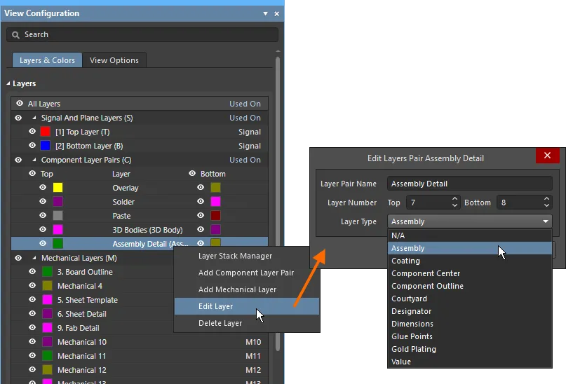
2. Right-click anywhere in the Layers region of the Layers & Colors tab, then select Add Component Layer Pair from the context menu. A new mechanical layer will be automatically added to bottom of the Component Layer Pairs (C) section.
3. Right-click anywhere in the Layers region of the Layers & Colors tab, then select Add Mechanical Layer from the context menu. A new mechanical layer will be automatically added to bottom of the Mechanical Layers (M) section.
4. Right-click or double-click on a Mechanical Layer to open the Edit Layer dialog. A Mechanical Layer may reside in the Component Layer Pairs (C) or Mechanical Layers (M) section. When a Mechanical Layer is renamed, the Edit Layer dialog's name will also reflect the name of the Mechanical Layer. For instance, if "Mechanical Layer 15" is being edited, the Edit Layer dialog will displayed as "Edit Layer Mechanical Layer 15" when windowed. When accessing the Edit Layer dialog, you may edit:
- Layer Name - use this text box to rename the Mechanical Layer.
- Layer Number - use this text box to manually input the desired Layer Number. If the number is unavailable, an exclamation point (
 ) will appear, and an available Layer Number will need to be selected to continue.
- Layer Type - use this drop-down to select the Layer Type in which you'd like the Mechanical Layer to reside. The chosen Layer Type will then appear in parenthesis alongside the name of the Mechanical Layer.
Any number of Mechanical Layers can be added to the PCB. Mechanical Layers also support defining the Layer Number, and setting the Layer Type. There are two sets of Layer Type options, a set for individual mechanical layers, and a set for Layer Pairs, as shown below.


As with other component layers, the software will automatically pre-pend the word Top or Bottom to the name to distinguish to which layer the pair is being referred.
To delete a layer, you can right-click on the desired layer and select Delete Layer. Depending on how the layer is being utilized, you will come across three options:
- If the layer can not be deleted because it contains component primitives that cannot be removed, an error pop-up will appear to alert you that the action cannot be completed.

- If the layer is associated with primitives that can be removed, a pop-up will appear to ask for confirmation of deletion.

3. If the layer is not associated with primitives, it will be deleted immediately upon clicking Delete Layer, without confirmation.
Only unused mechanical layers can be paired.
