알티움 디자이너에는 STEP, 파라솔리드 등 널리 사용되는 포맷에서 디자인 데이터를 가져오고 내보내 MCAD 툴과 교환할 수 있는 기능이 포함되어 있습니다.
STEP 파일 Import-Export 지원
Altium Designer는 물리적 설계 데이터의 활발한 교환을 통해 기계 설계 시스템 및 소프트웨어(MCAD)와 상호 작용할 수 있는 고급 기능을 제공합니다. ECAD-MCAD 도메인을 연결하는 다양한 시스템과 인터페이스는 3D 모델 설계 데이터를 위한 정보가 풍부한 일반 텍스트 인코딩 파일 형식을 제공하는 업계에서 승인한 STEP 프로토콜(St E 제품 모델 데이터의 Pxchange)과 같은 표준화된 데이터 형식에 의존합니다.
STEP 파일 형식 자체(*.step 또는 *.stp)는 CAD 데이터 교환을 위한 ISO 10303-21 (국제 표준화 기구) 사양에 정의되어 있으며 대부분의 MCAD 도구 및 시스템에서 지원됩니다. 기본적인 파일 교환 수준에서 Altium Designer는 3D STEP 파일에 대한 Export 및 Import 기능을 모두 제공합니다.
이는 소프트웨어 도메인 간에 고품질의 표준화된 3D 모델링 데이터를 자유롭게 교환할 수 있는 기반을 제공하여 ECAD-MCAD 설계 협업을 간소화하고 3D 모델 데이터의 품질과 정확성을 모두 향상시킵니다. STEP AP214와 레거시 AP203 형식은 모두 Altium Designer에서 지원되며, 내보낸 파일은 ISO-10303-21(AP214)을 준수합니다.
ISO 10303-21 사양 페이지를 참조하세요.
STEP 파일 형식에 대한 정보를 읽어보세요.
STEP 파일 Export
ECAD와 MCAD 세계 간의 데이터 교환 관계에서 중요한 기능은 물리적 클리어런스 확인을 위해 PCB 또는 멀티 보드 어셈블리를 기계 설계 소프트웨어로 포팅하는 기능입니다. 이는 설계가 컨트롤, 스위치, 커넥터 및 디스플레이와 같은 PCB 주변 장치를 노출하는 제품 인클로저와 밀접하게 일치하는 경우 특히 중요합니다.
이 경우 STEP 파일 형식의 고유한 범용성과 정확성 덕분에 치수 관계에 대한 높은 신뢰도를 바탕으로 포괄적인 PCB 모델링 데이터를 Altium Designer에서 MCAD 소프트웨어로 전송할 수 있습니다. 그런 다음 MCAD 설계자는 PCB 어셈블리 3D STEP 모델을 가져와 기계 설계에 배치하여 적절히 확인 및/또는 수정할 수 있습니다.
Export 사용
Altium Designer PCB 문서는 STEP 파일 형식으로 내보낼 수 있습니다. 출력 작업 파일에서 [Add New Export Output] 을 클릭하고 Export STEP 메뉴에서 항목을 선택합니다. 그런 다음 파일에서 직접 또는 프로젝트 릴리스 프로세스의 일부로 Export 출력을 생성할 수 있습니다.

또는 Altium Designer의 PCB 편집기 주 메뉴에서 File » Export » STEP 3D 명령을 선택합니다. 명령을 실행한 후 대상 파일 이름과 위치를 지정합니다.
추가된 STEP Export 출력을 더블 클릭하거나 File » Export » STEP 3D 명령을 실행하여 액세스할 수 있는 Export Options 대화 상자에는 생성된 파일에 포함할 보드 개체를 결정하는 옵션을 비롯한 다양한 선택 항목이 제공됩니다.
 내보낸 STEP 파일은 MCAD 애플리케이션에 표시되며, 상단 이미지 파일에는 패드 구멍이나 3D 바디가 포함되지 않고 하단 이미지 파일에는 모든 개체가 포함됩니다.
Options and Controls of the Export Options Dialog
STEP, PARASOLID 또는 VRML 형식의 파일로 내보내는 경우 Export Options 대화상자가 열립니다. 내용은 형식과 Export가 File » Export 명령을 사용하여 수행되는지, 아니면 출력 작업 파일의 일부로 구성된 출력기를 사용하여 수행되는지에 따라 약간씩 달라집니다. 아래에 변형된 내용이 강조 표시되어 있습니다.
Board Options
레이어 스택 영역 모드에서 구성할 때
PCB 패널의
Fold State 슬라이더로 정의한 접기 양이
Export Options 대화 상자가 열릴 때 기본 접기 양이 됩니다.
-
Skip Free 3D Bodies - 무료 3D 모델 없이 내보내려면 활성화합니다.
-
Skip Hidden 3D Bodies - 숨겨진 3D 모델 없이 Export를 활성화합니다.
-
Export As Single Part - 이 옵션은 STEP 파일로 내보낼 때만 적용됩니다. STEP 파일을 단일 파트 또는 컴포넌트당 하나의 모델로 내보내려면 선택합니다. 이 옵션을 활성화하면 STEP 파일은 어셈블리가 아닌 부품으로 저장됩니다.
Components With 3D Bodies
이러한 옵션은 File » Export 명령을 통해 대화 상자에 액세스할 때만 사용할 수 있습니다.
내보내는 파일에 포함할 구성요소를 선택할 수 있는 옵션을 선택합니다. 이 옵션은 Export 프로세스의 속도를 높이고 파일 크기를 줄이기 위해 전체 세부정보와 제한된 세부정보 중에서 선택할 수 있도록 설계되었습니다.
-
Export All - 모든 구성 요소를 내보내려면 선택합니다. 이 옵션은 속도가 느리고 내보내는 파일의 크기가 커집니다.
-
Export Selected - 선택한 컴포넌트만 내보내려면 선택합니다. 이 옵션은 속도가 빠르며 내보내는 파일의 크기가 줄어듭니다.
보드 컷아웃은 항상 Export에 포함됩니다.
2D에서는 내보낼 특정 컴포넌트나 구멍을 선택하는 것이 더 쉽습니다. 보드만 내보내려면 Export Selected 을 선택하고 문서에서 아무것도 선택하지 마세요. PCB가 장착되지 않은 프리플로팅 3D 바디도 익스포트에 포함됩니다. 포함하지 않으려면 프리플로팅 3D 바디를 선택하지 않고 Export Selected 옵션을 사용합니다.
3D Bodies Export Options
다음 옵션은 돌출된 (단순) 3D 바디와 STEP 모델 3D 바디가 모두 할당된 컴포넌트에 적용됩니다.
-
Prefer simple bodies - 컴포넌트의 돌출된(단순) 3D 바디 버전을 내보내려면 선택합니다.
-
Prefer generic 3D models - 일반 3D 바디 버전을 내보내려면 선택합니다.
-
Export both - 돌출된 버전과 일반 3D 바디 버전을 모두 내보내려면 선택합니다.
컴포넌트에 압출된 3D 바디만 사용할 수 있는 경우 항상 압출된 3D 바디만 익스포트됩니다.
Copper Export Options
이러한 옵션은 파라솔리드 형식으로 내보낼 때만 사용할 수 있습니다.
구리 Export 옵션을 선택하려면 다음 옵션을 사용합니다.
-
Export Without Copper - 구리 없이 내보내려면 선택합니다.
-
Export Copper Only - 구리만 내보내려면 선택합니다.
-
Export Selected Only - 선택한 개체에 속한 구리 개체를 내보내려면 선택합니다.
-
Export By Layer - 레이어별로 구리를 내보내려면 선택합니다. 드롭다운을 사용하여 다음 레이어 중 하나를 선택합니다:
-
Top Layer
-
Mid-Layer 1
-
Mid-Layer 2
-
Bottom Layer
선택한 레이어의 스루홀 패드와 비아 링을 포함하여 해당 레이어에 있는 구리 개체만 내보내야 하는 경우 이 모드를 선택합니다.
-
Export All - 모두 내보내려면 선택합니다.
Export Copper Only, Export Selected Only 또는 Export By Layer 옵션을 활성화하면 구리 이외의 Export 옵션이 선택되어 있어도 구리 객체만 내보냅니다. Export Without Copper 또는 Export All 을 사용하면 선택한 다른 컴포넌트 옵션에 따라 보드와 컴포넌트가 표시됩니다.
Pad Holes
다음 옵션은 File » Export 명령을 통해 대화 상자에 액세스한 경우에만 사용할 수 있습니다.
다음 옵션을 사용하여 내보낸 파일에 포함할 구멍을 선택합니다. 이 옵션은 Export 프로세스 속도를 높이고 파일 크기를 줄이기 위해 전체 세부정보와 제한된 세부정보 중에서 선택할 수 있도록 설계되었습니다.
-
Export All - 보드의 모든 구멍을 내보내려면 선택합니다. 이 옵션은 속도가 느리고 내보내는 파일의 크기가 커집니다.
-
Export Selected - 선택한 구멍만 내보내려면 선택합니다. 이 옵션은 속도가 빠르며 내보내는 파일의 크기가 줄어듭니다.
다음 옵션은 아웃잡 파일을 통해 대화 상자에 액세스한 경우에만 사용할 수 있습니다.
-
Export Mechanical Component Pad Holes - 기계 부품 패드 구멍을 익스포트하려면 이 상자를 선택합니다.
-
Export Electrical Component Pad Holes - 전기 컴포넌트 패드 구멍을 익스포트하려면 이 확인란을 선택합니다.
-
Export Free Pad Holes - 자유 패드 구멍을 내보내려면 이 확인란을 선택합니다.
Component Suffix
내보낸 컴포넌트의 접미사를 지정하려면 다음 옵션을 사용하세요.
-
None - 컴포넌트에 접미사가 적용되지 않습니다.
-
Board file name - 컴포넌트 접미사로 일반 3D 파일명을 사용합니다.
-
Custom - 를 선택하여 컴포넌트 접미사를 사용자 지정합니다. 텍스트 상자에 사용자 지정 접미사를 입력합니다.
Export 내보낸 파일에 대한 참고 사항
-
Export Options 대화 상자에서 Export Selected 옵션(3D 바디 및 패드 구멍)이 활성화되었지만 현재 PCB 편집기에서 no 오브젝트가 선택되어 있는 경우, 생성된 STEP 파일에는 해당 오브젝트 유형이 포함되지 않습니다.
-
보드는 항상 내보내집니다. 모든 컴포넌트를 제외하려면(보드만 내보내려면) 컴포넌트를 선택하지 않은 상태에서 Export Selected 옵션을 활성화합니다.
-
일부 컴포넌트만 내보내려면 일반적으로 2D 디스플레이 모드에서 컴포넌트를 선택하는 것이 더 쉽습니다.
-
Export as Single Part 옵션을 선택하면 생성된 STEP 모델이 컴포넌트 모델의 어셈블리가 아닌 단일 부품으로 저장됩니다. 이렇게 하면 내보낸 STEP 모델이 단순화되지만 수신하는 MCAD 응용 프로그램에서 개별 구성 요소를 선택할 수 없습니다.
-
Export 3D 기능으로 생성된 STEP 파일은 소스 PCB 설계의 원점을 기준으로 모델 그래픽을 배치합니다. 해당 파일을 가져오는 데 사용되는 소프트웨어는 포함된 위치 명령에 응답하거나 응답하지 않을 수 있으며, 가져온 모델이 표시되지 않으면 현재 줌 수준에서 화면에서 벗어날 수 있습니다.
-
Free 3D Bodies 인클로저와 같이 PCB 편집기에 배치된 추가 3D 모델입니다.
-
3D Bodies Export Options 은 PCB 라이브러리 에디터의 컴포넌트 풋프린트에 추가된 3D 바디/모델에 적용됩니다. simple bodies 이라는 용어는 압출, 원통형 또는 구형 3D 바디 개체를 의미합니다.
-
STEP 파일에서 각 컴포넌트는 해당 지정자로 식별됩니다. MCAD 설계자가 여러 보드를 단일 MCAD 파일로 가져와야 하는 경우 지정자 충돌이 발생할 수 있으므로 이를 방지하기 위해 Component Suffix.
-
Export Folded Board 옵션은 디자인에 벤딩 라인이 정의된 경우에만 작동합니다. 부분적으로 접힌 보드를 내보내려면 Export 명령을 실행하기 전에 PCB 패널의 Layer Stack Region 모드에서 Fold State 슬라이더를 사용하여 접는 양을 구성합니다. 정의된 값은 Export Options 대화 상자에 자동으로 적용됩니다.
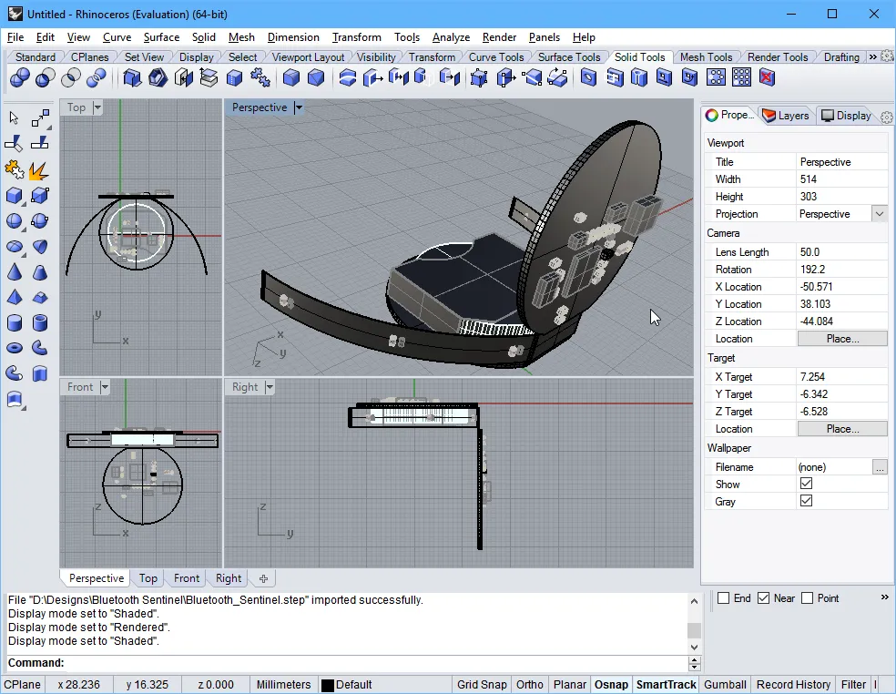
부분적으로 접힌 리지드 플렉스 보드를 PCB 편집기에서 내보내고 Rhinoceros 3D MCAD 설계 소프트웨어로 가져온 모습.
-
기계 도면/보기 소프트웨어에 액세스할 수 없는 경우, 내보낸 STEP 파일을 Altium Designer에서 배치된 3D 바디 개체로 다시 가져와서 확인할 수 있습니다.
Altium Designer 멀티보드 어셈블리 문서를 STEP 파일 형식으로 내보낼 수 있습니다. 출력 작업 파일에서 [Add New Export Output] 메뉴의 MBA Export STEP 항목을 사용하거나 Altium Designer의 멀티보드 어셈블리 편집기 메인 메뉴에서 File » Export » STEP 3D 명령을 선택합니다.
IPC Component Wizard에서 저장하기
PCB 라이브러리 편집기에서 IPC 호환 풋프린트를 생성하는 자동화된 IPC Compliant Footprint Wizard 는 생성된 풋프린트 모델을 3D STEP 파일로 저장(및 미리 보기)할 수 있는 추가 옵션을 제공합니다. STEP 기반 모델은 생성된 IPC 호환 풋프린트에 임베드하거나 지정된 위치에 *.step 파일로 저장할 수 있으며, 후자의 옵션을 사용하면 필요에 따라 3D 모델을 재사용하거나 배포할 수 있습니다.
IPC Component Wizard 은 PCB 풋프린트 편집기(Tools » IPC Compliant Footprint Wizard)에서 실행되며 마법사의 두 번째 페이지( Footprint Destination )에서 STEP Export 옵션이 활성화됩니다. 생성된 STEP 파일 모델은 마법사에 입력한 부품 치수와 정확하게 일치합니다.
 마법사에서는 컴포넌트에 대한 STEP 모델을 생성하고 임베드하는 옵션과 함께 이를 STEP 3D 모델 파일로 저장할 수도 있습니다.
STEP 파일 Import
PCB 또는 PCB 풋프린트로 Import
STEP 파일은 동일한 메커니즘을 사용하는 두 가지 방법을 통해 Altium Designer에서 가져와서 사용할 수 있습니다. 사용되는 접근 방식은 기본적으로 STEP 파일이 설계에 적용되는 방식에 따라 달라집니다:
-
MCAD 애플리케이션에서 생성된 인클로저와 같이 최종 제품 설계의 기계적 요소를 나타내는 STEP 파일은 일반적으로 PCB 레이아웃으로 가져옵니다.
-
3D 컴포넌트 본체를 나타내는 STEP 파일(인터넷에서 다운로드하거나 로컬에서 생성)은 일반적으로 PCB 풋프린트로 가져옵니다.
Altium Designer의 PCB 및 PCB 풋프린트 도메인 내에서 STEP 파일은 필요에 따라 배치 및 정렬되는 전용 3D 바디 개체로 임포트됩니다. 자세한 내용은 3D 바디 오브젝트 배치 섹션을 참조하십시오.
Exporting the Enclosure and Board Shape from MCAD for Use in Altium Designer
일반적인 접근 방식은 기계 설계자가 초기 컨셉 모델을 개발하여 관련된 모든 사람이 제품의 모양을 파악할 수 있도록 하는 것입니다. 여기에서 기계 설계자는 인클로저 디자인을 구체화하고 초기 보드 모양을 정의합니다.
이 인클로저와 보드 모양은 MCAD 도구에서 STEP 형식으로 저장하고 PCB 편집기 디자인 공간에 배치하여 ECAD 디자이너에게 전달할 수 있습니다. Altium Designer에는 MCAD 보드 모양에서 직접 ECAD 보드 모양을 재정의하는 명령이 포함되어 있습니다.
STEP은 복잡하고 매우 상세한 파일 형식입니다. 설계 데이터 전송의 성공을 극대화하려면 다음 사항에 유의하세요:
-
보드 모양은 별도의 하위 어셈블리인 경우 인클로저 내부에서 내보낼 수 있습니다. 이 작업을 완료한 경우 PCB 편집기에서 몇 번의 클릭만으로 기계적 정의에서 ECAD 보드 모양을 다시 정의할 수 있습니다.
-
가능하면 AP214 형식을 사용하세요.
-
가능한 경우 서피스 또는 솔리드 지오메트리 옵션을 사용합니다.

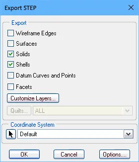
솔리드웍스(첫 번째 이미지) 및 PTC Creo(구 Pro/E)(두 번째 이미지)에 적합한 Export 옵션입니다.
멀티보드 어셈블리로 Import
메인 메뉴에서 Design » Insert STEP Part 명령을 사용하여 활성 멀티보드 어셈블리 문서에 STEP 모델을 추가할 수 있습니다.
파라솔리드 파일 Import-Export 지원
파라솔리드 파일 Export
Altium Designer PCB 문서를 Parasolid 파일 형식으로 내보낼 수 있습니다. 출력 작업 파일에서 [Add New Export Output] 을 클릭하고 Export PARASOLID 메뉴에서 항목을 선택합니다. 그런 다음 파일에서 직접 또는 프로젝트 릴리스 프로세스의 일부로 Export 출력을 생성할 수 있습니다.

또는 Altium Designer의 PCB 편집기 메인 메뉴에서 File » Export » PARASOLID 명령을 선택합니다.
패널화된 PCB (임베디드 보드 어레이)를 Parasolid 형식으로 내보낼 때 경로 도구 경로가 내보낸 파일의 모든 보드 레이어를 통해 절단되고 소스 보드의 캐비티 및 보드 컷아웃이 패널화된 PCB에서 고려됩니다.
파라솔리드 파일 Import
Altium Designer의 PCB 및 PCB 풋프린트 도메인 내에서 파라솔리드 파일을 필요에 따라 배치 및 정렬되는 전용 3D 바디 오브젝트로 가져옵니다. 자세한 내용은 3D 바디 객체 배치 섹션을 참조하십시오.
SolidWorks 파트 파일 Import 지원
Altium Designer의 PCB 및 PCB 풋프린트 도메인 내에서 SolidWorks 파트 파일(*.sldprt)을 필요에 따라 배치 및 정렬되는 전용 3D 바디 개체로 가져옵니다. 자세한 내용은 3D 바디 객체 배치 섹션을 참조하십시오.
일반 3D 모델을 3D 바디 객체와 함께 사용하는 경우 SOLIDWORKS 버전 2022 또는 2023에서 생성된 SOLIDWORKS 부품 파일(*.SldPrt) 형식의 3D 모델을 가져올 수 있습니다.
VRML 파일 Export 지원
Altium Designer PCB 문서를 VRML 파일 형식으로 내보낼 수 있습니다. 출력 작업 파일에서 [Add New Export Output] 을 클릭하고 Export VRML 메뉴에서 항목을 선택합니다. 그러면 파일에서 직접 또는 프로젝트 릴리스 프로세스의 일부로 Export 출력을 생성할 수 있습니다.

또는 Altium Designer의 PCB 편집기 메인 메뉴에서 File » Export » VRML 명령을 선택합니다.
IDF 파일 Import-Export 지원

IDF 파일 Export
Altium Designer PCB 문서를 IDF 파일 형식으로 내보낼 수 있습니다. 출력 작업 파일에서 [Add New Export Output] 을 클릭하고 Export IDF 메뉴에서 항목을 선택합니다. 그런 다음 파일에서 직접 또는 프로젝트 릴리스 프로세스의 일부로 Export 출력을 생성할 수 있습니다.

또는 Altium Designer의 PCB 편집기 메인 메뉴에서 File » Export » IDF Board 명령을 선택합니다.
File Export IDF 대화상자는 내보낸 IDF 파일의 속성을 구성하는 컨트롤을 제공합니다. 이 대화 상자는 Outputjob 파일에서 추가된 IDF Export 출력을 두 번 클릭하거나 File » Export » IDF Board 을 선택한 후 Export File 대화 상자에서 Save 을 클릭하여 액세스할 수 있습니다.
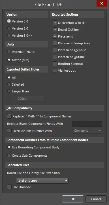
File Export IDF 대화 상자
Options and Controls of the File Import IDF Dialog
-
Version - 적절한 버전을 선택했습니다.
-
Units - 적절한 단위를 선택합니다: Imperial 또는 Metric.
-
Exported Drilled Holes
-
All - 를 선택하여 드릴링된 모든 구멍을 내보냅니다.
-
Selected - 선택한 드릴링된 구멍만 내보내려면 선택합니다.
-
Larger Than - 텍스트 상자에 지정된 크기보다 큰 드릴된 구멍만 내보내려면 선택합니다.
-
Exported Sections - 원하는 섹션의 확인란을 활성화합니다.
-
File Compatibility
-
Replace '.' With '_' In Component Names - 컴포넌트 이름에서 마침표 문자를 밑줄 문자로 바꾸려면 이 확인란을 선택합니다.
-
Replace Blank Component Fields With - 빈 컴포넌트 필드를 대체할 텍스트를 입력합니다.
-
Override Part Number With - 파일 생성 중에 부품 번호를 재정의하려면 활성화합니다. 드롭다운 메뉴에서 다음 옵션 중 하나를 선택하여 부품 번호를 재정의할 수 있습니다. 드롭다운 메뉴는 Override Part Number With 옵션이 활성화된 경우에만 사용할 수 있습니다.
-
Comment
-
Item HRID
-
Revision HRID
-
Library REF
-
의 경우 괄호 사이에 구성 요소 이름의 기준이 될 원하는 회로도 매개변수를 입력합니다.
-
Component Outlines From Multiple Component Bodies
-
Use Bounding Component Body - 바운딩 컴포넌트 본문을 사용하려면 선택합니다.
-
Create Sub Components - 하위 컴포넌트를 만들려면 선택합니다.
-
Generated Files - iDF 파일을 내보내면 PCB의 물리적 크기와 모양, 구성 요소의 위치에 대한 정보가 포함된 파일과 이름, 크기, 모양 등 각 구성 요소에 대한 정보가 포함된 파일 두 개가 생성됩니다. 이를 일반적으로 각각 보드 파일과 라이브러리 파일이라고 합니다. CAD 패키지마다 보드 파일과 라이브러리 파일에 다른 파일 확장자를 사용합니다. 드롭다운을 사용하여 생성된 파일의 보드 파일 및 라이브러리 파일 확장자를 선택합니다. 선택할 수 있는 확장자는 다음과 같습니다:
-
.brd 및 .pro
-
.brd 및 .lib
-
.emn 및 .emp
-
.bdf 및 .ldf
-
.idb 및 .idl
-
.idf 및 .lib
-
Use Unicode - 이 확인란을 선택하면 생성된 파일의 텍스트에 유니코드 표준을 사용합니다.
IDF 파일 Import
IDF 파일을 활성 PCB 문서로 가져오려면 Altium Designer의 PCB 편집기 주 메뉴에서 File » Import » IDF Board 명령을 선택합니다. 명령을 선택하면 가져온 IDF 파일의 속성을 구성할 수 있는 File Import IDF 대화 상자가 열립니다.
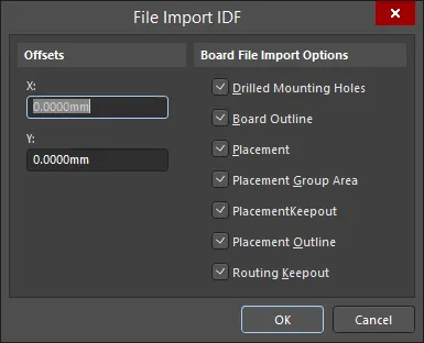
File Import IDF 대화 상자
Options and Controls of the File Import IDF Dialog
-
Offsets - 텍스트 상자에 X 및 Y 에 원하는 오프셋 거리를 입력합니다.
-
Board File Import Options - 가져오려는 항목의 확인란을 활성화합니다.
-
OK - 를 클릭하여 Import 프로세스를 시작합니다.
IDX 파일 Import-Export 지원
점점 더 많은 전자 제품에 전기 및 기계 부품이 포함되고 제품 출시 주기가 짧아짐에 따라 ECAD와 MCAD 도메인 간의 협업이 더욱 강화되어야 할 필요성이 커지고 있습니다. 하지만 이러한 협업이 항상 원활하게 이루어지는 것은 아닙니다. 전기 설계자와 기계 설계자는 종종 이메일을 주고받거나 서로의 설계 툴을 사용해야 하는 등, 기존의 익숙함에서 벗어나 새로운 영역에 도전해야 하는 경우가 많습니다. 한 가지 해결책은 신뢰할 수 있는 작업 환경을 벗어나지 않고도 두 사람이 아이디어와 변경 제안을 그래픽으로 전달할 수 있는 협업 방법을 사용하는 것입니다. 이러한 방법은 XML 기반 교환 파일 형식( IDX (Incremental Design EX변경 형식)을 통해 제공됩니다.
이 중간 교환 파일(*.idx)을 사용하면 전기 설계자는 기계 설계자에게 필요한(그리고 가치 있는) 보드 설계 변경 사항만 내보낼 수 있습니다. 반대로, 기계 설계자는 변경 제안을 전기 설계자에게 다시 플로팅할 수 있으며, 전기 설계자는 해당 변경 사항을 다시 설계로 가져올 수 있습니다.
이러한 ECAD와 MCAD 도메인 간의 협업 표준에 대한 지원은 MCAD IDX Exchange 확장을 통해 Altium Designer에서 제공됩니다. 이 확장 기능을 사용하면 IDX 교환 형식을 사용하여 Altium Designer와 기계식 CAD 애플리케이션(예: SOLIDWORKS) 간에 데이터를 점진적으로 교환할 수 있습니다. 기능에는 변경 요청 지원과 Cu 지오메트리 전송이 포함됩니다.
공동 작업을 위한 기준 파일 시작하기
협업은 전기 설계자가 초기 IDX 파일을 생성하거나 기계 설계자가 주도하는 등 어느 방향에서든 시작할 수 있습니다. 전기 설계자가 생성한 파일을 ECAD 베이스라인 파일(ECAD Baseline.idx)이라고 하며, 이후 기계 설계자가 사용할 수 있습니다. 기계 설계자가 생성하는 경우 이를 MCAD 베이스라인 파일(MCAD Baseline.idx)이라고 하며, 이후 전기 설계자가 사용할 수 있습니다.
Altium Designer에서 Export(ECAD에서 베이스라인 생성)
Altium Designer 내에서 협업을 위한 기본 인터페이스는 MCAD IDX Exchange 패널로, PCB 편집기가 활성화되어 있을 때 Altium Designer의 오른쪽 하단에 있는  버튼을 클릭한 다음 메뉴에서 MCAD IDX Exchange 항목을 선택하여 액세스할 수 있습니다.
이 패널은 기본 Tools 메뉴에서 MCAD IDX Exchange 명령을 사용하여 액세스할 수도 있습니다.
공동 작업을 시작하려면 Export Baseline 버튼을 클릭합니다. 구리 개체 Export를 비롯한 옵션을 제공하는 Export EDMD Baseline 대화 상자가 표시됩니다.
구리 개체를 내보내면 IDX 파일이 훨씬 커지고 MCAD 측에서 처리하는 속도가 느려집니다. 또한 IDX 기술은 구리 개체에 대한 변경 감지 기능을 지원하지 않습니다.
 ECAD 베이스라인을 생성하여 Altium Designer 내에서 협업을 시작하세요.
Altium Designer로 Import(MCAD 기준선 생성)
기준선 파일이 MCAD 측에서 생성된 경우 File » Import » MCAD IDX Baseline 명령을 사용하여 Altium Designer로 가져올 수 있습니다. Import MCAD Baseline 대화 상자가 열립니다. 이를 사용하여 MCAD 베이스라인 파일(MCAD Baseline.idx)과 제안된 변경 사항을 동기화할 PCB 문서를 찾아 지정합니다.
 MCAD 베이스라인을 가져와서 Altium Designer 내에서 공동 작업을 수락합니다.
-
Input MCAD Baseline File -
 을 클릭하여 가져올 IDX 파일을 찾아 선택합니다.
-
Output PCB File -
 을 클릭하여 제안된 변경 사항을 동기화할 원하는 PCB 파일을 찾아 선택합니다.
MCAD 베이스라인 IDX 파일을 가져오면 MCAD IDX Exchange 패널을 통해 공동 작업이 진행됩니다.
공동 작업 폴더
Altium Designer에서 공동 작업을 시작하면(IDX 베이스라인 파일 생성) 원본 보드 디자인 프로젝트 아래에 공동 작업 폴더가 생성됩니다. 폴더의 이름은 .PcbDoc_EDMD 형식의 PCB 문서 이름을 사용하여 지정됩니다. 폴더에는 두 개의 파일이 포함됩니다:
-
AD_EDMD_State.xml
-
ECAD Baseline.idx
Show In Explorer 컨트롤(초기 Export 후에만 사용 가능)을 클릭하거나  버튼을 클릭한 다음 관련 메뉴에서 Open Collaboration Folder 항목을 선택하여 MCAD IDX Exchange 패널에서 생성된 폴더에 빠르게 액세스할 수 있습니다.
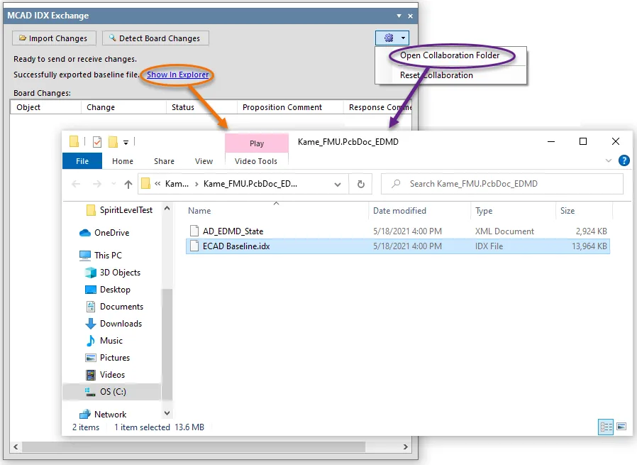
폴더 및 기준 파일 생성.
변경 내용 동기화
MCAD IDX Exchange 패널은 ECAD 도메인과 MCAD 도메인 간에 변경 사항을 동기화하기 위한 제어 기능을 제공합니다. 변경 사항은 IDX 변경 파일을 통해 제안됩니다:
-
기계 설계자가 변경 사항을 제안하고 새 IDX 변경 파일로 전송한 경우, 패널에서 해당 변경 사항을 PCB 설계로 수신(Import)하여 고려할 수 있도록 허용합니다.
-
보드에 변경 사항이 있는 경우 패널은 이러한 변경 사항(구리 변경 제외)을 감지하고 이를 나열하여 나중에 기계 설계자가 사용할 수 있는 IDX 변경 사항 파일로 내보낼 수 있도록 준비할 수 있습니다.
보드 변경 사항 감지 및 Export
구성 요소를 제거하는 등 PCB 문서를 변경하는 경우 MCAD IDX Exchange 패널 상단의  버튼을 클릭하면 해당 변경 사항을 감지할 수 있습니다. 감지된 변경 사항은 패널의 Board Changes 영역에 다음과 같이 나열됩니다:
-
Object - 예를 들어 컴포넌트 지정자.
-
Change - 예를 들어 디자인에서 제거된 컴포넌트의 경우 Removed, 추가된 컴포넌트의 경우 Added.
-
Status - 변경이 ECAD 쪽에서 시작되었으므로 Proposed 이 됩니다.
-
Proposition Comment - 기계 설계자에게 변경 사항을 설명하기 위한 메모입니다. 필요에 따라 입력합니다.
 보드의 변경 사항을 감지합니다.
모든 변경 사항을 적용하고, 감지하고, 제안 설명을 추가한 후에는  버튼을 사용하여 해당 변경 사항을 내보낼 수 있습니다. 그러면 IDX 변경 사항 파일(ECAD Changes n.idx)이 생성됩니다.
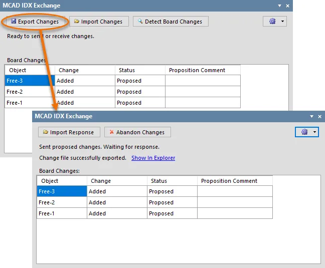
보드에 제안된 변경 사항이 적용되면 Export를 통해 IDX 변경 사항 파일을 생성하여 제안된 변경 사항을 기계 설계자에게 보냅니다.
이제 기계 설계자가 변경 제안을 가져와서 확인하는 것은 기계 설계자의 몫입니다. 그런 다음 제안된 각 변경 사항을 차례로 수락하거나 거부하고 IDX 응답 파일(MCAD Response n.idx)로 응답을 보냅니다. 응답을 받으면  버튼을 사용하여 응답을 가져옵니다. 응답 파일에 변경 사항을 적용하려면
  버튼을 클릭하면 ECAD 측에서 기계 설계자에게 다시 IDX 응답 파일을 생성합니다(ECAD Response n.idx).
이 "핸드셰이킹"을 통해 양측이 변경 사항을 동기화할 수 있습니다.
제안된 변경 사항을 취소하려면

버튼을 클릭하면
Board Changes 목록이 지워집니다.
변경 내용 Import
기계 설계자가 변경 사항을 제안하는 경우 해당 변경 사항은 IDX 변경 사항 파일(MCAD Changes n.idx)에 제안됩니다. 패널의  버튼을 사용하여 변경 사항을 가져옵니다. 변경 사항은 패널의 Changes from Mechanical CAD 영역에 다음과 같이 나열됩니다:
-
Object - 예를 들어 컴포넌트 지정자.
-
Change - 예를 들어 디자인 내에서 이동한 컴포넌트의 경우 Moved.
-
Status - 변경이 MCAD 쪽에서 시작되었으므로 Proposed 이 됩니다.
-
Proposition Comment - 전기 설계자에게 변경 사항을 설명하는 메모입니다.
 기계 설계자가 제안한 변경 사항을 패널로 가져옵니다.
이제 전기 설계자가 제안된 각 변경 사항을 차례로 보고 수락하거나 거부하는 것은 사용자의 몫입니다. 제안된 변경 사항을 수락하려면 관련 Accept 확인란을 선택합니다. 거부하려면 이 확인란을 선택하지 않은 상태로 둡니다. 해당 Response Comment 필드에 응답을 입력할 수도 있습니다.
제안된 변경 사항이 모두 수락/거부되면  버튼을 클릭합니다. 수락된 변경 사항이 PCB 문서에 적용되고 IDX 응답 파일(ECAD Response n.idx)이 생성되어 기계 설계자에게 다시 보낼 준비가 됩니다.
협업 재설정
프로젝트의 공동 작업을 완전히 재설정하려면  버튼을 클릭한 다음 관련 메뉴에서 Reset Collaboration 항목을 선택하세요. 패널의 모든 현재 항목이 지워지고 공동 작업 폴더의 모든 파일이 삭제됩니다. 그러면 다시 원점으로 돌아가서 기준 파일을 내보내거나 파일을 가져와서 공동 작업을 새로 시작할 수 있습니다.
재설정 전에 디자인에 적용된 모든 변경 사항은 그대로 유지됩니다.