Textオブジェクトは、選択したレイヤー上に単一行の文字列、または複数行のテキストフレームを、さまざまな表示スタイル/形式(一般的なバーコード規格やQRコードを含む)で配置します。ユーザー定義テキストとして使用できるほか、「特殊文字列(special string)」と呼ばれる特別な種類の文字列として、基板やシステム情報、または基板上のユーザーパラメータ値を表示するためにも使用できます。テキストフレームはサイズ変更可能な長方形領域で、複数行のテキストを含められます。また、フレームの範囲内に収めるために、テキストの自動折り返しやクリップ(はみ出し部分の切り取り)を行えます。
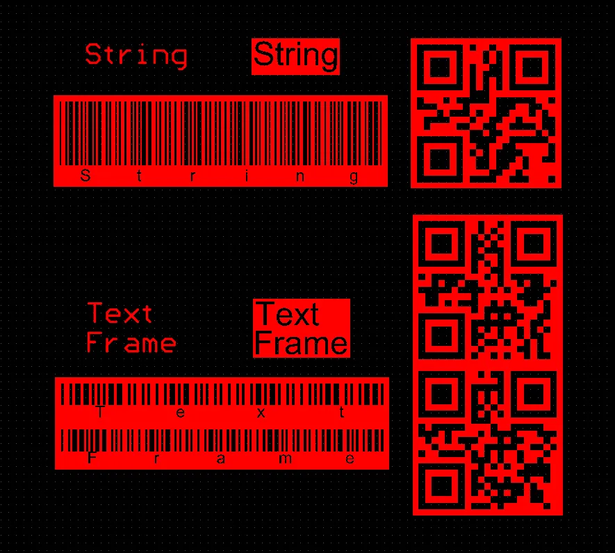
配置済みTextオブジェクト
Textオブジェクトは、PCBエディタおよびPCBフットプリントエディタの両方で、メインメニューからPlace » StringまたはPlace » Text Frameコマンドを選択して配置できます。文字列配置コマンドを起動すると、カーソルが十字カーソルに変わり、テキスト配置モードに入ります。Textオブジェクトがカーソルに追従して表示されます。
-
カーソルを位置決めしてからクリックするか、Enterを押してTextオブジェクトを配置します。
-
続けて別のTextオブジェクトを配置するか、右クリックするか、Escを押して配置モードを終了します。
選択した配置コマンド(
Place » Stringまたは
Place » Text Frame)に応じて、配置中のTextオブジェクトは
Stringまたは
Frameモードになります。これは配置中または配置後に、
Propertiesパネルで変更できます。
配置中に実行できる追加操作は次のとおりです。
-
Spacebarを押すと反時計回りに回転し、Shift+Spacebarを押すと時計回りに回転します。回転量は、PreferencesダイアログのPCB Editor – General pageで定義されているRotation Stepの値に従います。
-
XまたはYキーを押すと、X軸またはY軸に沿ってTextオブジェクトをミラーします。
-
Lキーを押すと、Textオブジェクトを基板の反対面へ反転します。
-
(テンキーの)+および-キーを押すと、設計内で表示中の全レイヤーを前後に切り替え、配置レイヤーを素早く変更できます。
グラフィカル編集では、設計空間内で配置済みTextオブジェクトを直接選択し、位置、回転、向き、サイズを変更できます。
Textオブジェクトを選択すると、次の編集ハンドルが使用できます。
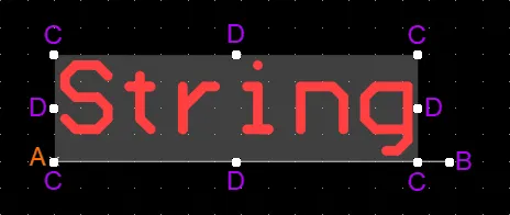
選択されたText
-
Bをクリックしてドラッグすると、参照点A(小さなxで示されます)を中心にTextオブジェクトを回転できます。
-
Cをクリックしてドラッグすると、Textオブジェクトの外接ボックスを縦横同時にサイズ変更できます。
-
Dをクリックしてドラッグすると、Textオブジェクトの外接ボックスを縦方向/横方向それぞれ個別にサイズ変更できます。
-
編集ハンドルから離れたTextオブジェクト上の任意の場所をクリックしてドラッグすると、再配置できます。ドラッグ中に、コメントを回転またはミラーできます。
-
Spacebarを押すと反時計回りに回転し、Shift+Spacebarを押すと時計回りに回転します。回転量は、PreferencesダイアログのPCB Editor – General pageで定義されているRotation Stepの値に従います。
-
XまたはYキーを押すと、X軸またはY軸に沿ってTextオブジェクトをミラーします。
-
新規に配置した文字列オブジェクトのデフォルトテキストはStringです。配置後(配置前または配置中に変更していない場合)は、Propertiesパネルを通じて文字列のプロパティを表示し、テキスト入力ウィンドウで必要に応じてこのテキストを変更してください。
-
本ソフトウェアでは、Textオブジェクトをバーコードシンボルとして任意のレイヤー上のPCBに直接配置でき、製造工程の一部としてPCBにバーコードを容易に印字できます。Textオブジェクトをバーコードとして使用する方法の詳細は、Including Barcodes & LogosページのAdding a Barcodeセクションを参照してください。
-
本ソフトウェアでは、TextオブジェクトをQRコードとして任意のレイヤー上のPCBに直接配置でき、製造工程の一部としてPCBにQRコードを容易に印刷できます。TextオブジェクトをQRコードとして使用する方法の詳細は、Including Barcodes & LogosページのAdding a QR Codeセクションを参照してください。
特殊文字列(Special Strings)
Textオブジェクトは、現在のPCBレイヤー上にユーザー定義テキストを配置するために使用できますが、配置できるのはonlyユーザー定義テキストだけではありません。ドキュメント作成を支援するために、special stringsという概念が用意されています。これらは、出力生成時にPCB上へ表示される設計/システム/プロジェクト情報のプレースホルダーとして機能します。

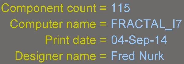
設計、システム、および設計パラメータの特殊文字列の例。ソース文字列(1枚目)と変換後(2枚目)を示します。
PCBドキュメントで利用できる特殊文字列は、複数のソースから提供されます。
-
新規PCBドキュメントで使用できる、既定の定義済み特殊文字列セットが用意されています。
-
カスタム特殊文字列は、プロジェクトレベル(これらのパラメータはProject OptionsダイアログのParameters tabで定義)およびバリアントレベル(これらのパラメータはEdit Project Variant dialog、またはVariant ManagerのVariantモードにおけるPropertiesパネル で定義)で追加パラメータを定義することで追加できます。
-
回路図ドメインでコンポーネントに追加したUser Parametersは、ECOを介して転送され、PCBコンポーネントでも利用可能になります。コンポーネントパラメータを参照する特殊文字列をソースライブラリレベルでPCBフットプリントに追加した場合、その文字列はPCBコンポーネント配置時に、ターゲットのメカニカルレイヤーまたはオーバーレイ上で解釈されます。
特殊文字列の使用に関する注意
-
特殊文字列は、文字列が「.」(ドット)で始まることで示されます(例:.Layer_Name、.Net_Countなど)。文字列が「.」で始まる場合、文字列全体が「特殊」文字列として扱われます。この構文はユーザーパラメータ参照でも使用され、パラメータ名の前に「.」(ドット)を付けます。
-
PCBテキスト内に複数の特殊文字列を含めるには、各特殊文字列をアポストロフィ( ' )で囲みます。例:'.Pcb_File_Name_No_Path' '.Print_Date'。
-
連結した特殊文字列の間に、テキスト、スペース、特殊文字を挿入することもできます。例:FileName= '.Pcb_File_Name_No_Path' : PrintDate = '.Print_Date'。
-
プロジェクトおよびバリアントのパラメータ名の中でも、スペースや特殊文字を使用できます。
-
一部の特殊文字列の値は、.Legend、.Plot_File_Name、.Printout_Nameなど、該当する出力を生成したときにのみ確認できます。ほとんどの特殊文字列は画面上で確認できます。
PCBプロジェクトのドキュメントを生成してWorkspaceへリリースする際には、そのドキュメントがどのItemおよびRevisionに対応するのか、またリリースに使用した設計プロジェクトの構成や適用される駆動バリアントを示す手段が必要です。これを管理するための特殊文字列セットが用意されており、.PCBConfigurationName、.ItemAndRevision、.VariantNameなどが含まれます。これらの特殊文字列は、出力生成時(PCBを3D表示している場合を除く。3D表示自体も出力と見なされます)まで解釈されません。これらの文字列を使用して提供される情報は、Gerber/ODB++ファイル、Final Artwork印刷、PCB印刷、PCB 3D印刷、PCB 3D Video、Assembly図面などの生成出力で確認できます。
-
特殊文字列は、画面表示用に自動的に変換されます。文字列を変換できない場合は、入力した文字列の値、またはメッセージが表示されます。たとえば、プロジェクトがバージョン管理下にない状態で特殊文字列.VersionControl_RevNumberをPCB上に配置すると、メッセージNot in Version Controlが表示されます。
-
特殊文字列の識別を支援するため、View Configuration panelにはSpecial Stringsオプションが含まれています。このオプションを有効にすると、変換された特殊文字列から構成される配置済みTextオブジェクトには、未変換の特殊文字列名が重ねて表示(ラベル表示)されます。

特殊文字列の配置
PCBで特殊文字列を使用するには、Textオブジェクトを配置し、PropertiesパネルでTextフィールドのドロップダウン(Stringモード)または ドロップダウン(Frameモード)から特殊文字列名を選択します。
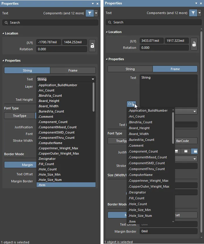
配置済み文字列オブジェクトで特殊文字列にアクセスする。
PCBドキュメントで使用できる、事前定義されたシステムベースの特殊文字列は次のとおりです。
-
.Application_BuildNumber – PCBが現在ロードされているソフトウェアのバージョン。Gerber出力を生成する際、この文字列を使用して設計作成に用いたソフトウェアビルドを記録できます。
-
.Arc_Count – PCB上のアーク数。
-
.BlindVia_Count – PCB上のブラインドビア数。
-
.Board_Height – PCB基板の縦方向サイズ。
-
.Board_Width – PCB基板の横方向サイズ。
-
.BuriedVia_Count – PCB上の埋め込みビア(buried via)数。
-
.Comment – コンポーネントのコメント文字列(ライブラリエディタでコンポーネントフットプリントの一部として任意のレイヤーに配置)。
-
.Component_Count – PCB上のコンポーネント数。
-
.ComponentMixed_Count – PCB上の混在パッド(mixed pads)を持つコンポーネント数。
-
.ComponentSMD_Count – PCB上のSMDパッドを持つコンポーネント数。
-
.ComponentThru_Count – PCB上のスルーホールパッドを持つコンポーネント数。
-
.ComputerName– ソフトウェアがインストールされ、実行されているコンピュータの名前。
-
.CopperInner_Weight_Max – 内層における銅箔の最大厚(銅量)。
-
.CopperOuter_Weight_Max – 外層における銅箔の最大厚(銅量)。
-
.Designator – コンポーネントのデジグネータ文字列(ライブラリエディタ内で、コンポーネントのフットプリントの一部として任意のレイヤーに配置)。
-
.Fill_Count – PCB上のフィルの数。
-
.Hole_Count – PCB上のドリル穴の数。
-
.Hole_Size_Min – PCB上の最小穴径。
-
.Hole_Size_Num – PCB上のユニークな穴径の数。
-
.Item – 生成データが関連するItem(例: D-810-2000)。このデータはそのItemを作成するために使用されます。
-
.ItemAndRevision – 生成データが関連するItemおよびその特定リビジョン(形式:<Item ID>-<Revision ID>、例: D-810-2000-01.A.1)。このデータは、その特定Itemのその特定リビジョンを作成するために使用されます。
-
.ItemRevision – 生成データが関連するItemの特定リビジョン(例: 01.A.1)。データはターゲットサーバー内のそのItem Revisionに保存されます。
-
.ItemRevisionBase – Item Revisionの命名スキームにおけるBase Level部分(例: 1)。
-
.ItemRevisionLevel1 – Item Revisionの命名スキームにおけるLevel 1部分(例: A)。
-
.ItemRevisionLevel1AndBase – Item Revisionの命名スキームにおけるLevel 1およびBase Level部分(例: A.1)。
-
.ItemRevisionLevel2 – Item Revisionの命名スキームにおけるLevel 2部分(例: 01)。
-
.ItemRevisionLevel2AndLevel1 – Item Revisionの命名スキームにおけるLevel 2およびLevel 1部分(例: 01.A)。
-
.Layer_Count – PCB上の銅層数。
-
.Layer_Name – 文字列が配置されているレイヤー名。
-
.Legend – メカニカルドリルプロット用のシンボル凡例。この文字列はDrill Drawingレイヤーに配置した場合にのみ有効です。注:これはレガシー機能です。より詳細なドリル情報にはDrill Tableオブジェクトを配置してください。
-
.MicroVia_Count – PCB上のマイクロビア数。
-
.ModifiedDate – PCBの更新日スタンプ。自動的に入力されます。例: 23/09/2015。
-
.ModifiedTime – PCBの更新時刻スタンプ。自動的に入力されます。
-
.Net_Count – PCB上の異なるネットの総数。
-
.Net_Names_On_Layer – 特定レイヤー上のすべてのネット名。この文字列は内部プレーンレイヤーに配置した場合にのみ有効です。
-
.Pad_Count – PCB上のパッド数。
-
.PadSMD_Count – PCB上のSMDパッド数。
-
.PadThru_Count – PCB上のスルーホールパッド数。
-
.Pattern – PCBで使用されているコンポーネントフットプリント名。
-
.Pcb_File_Name – PCBドキュメントのパスとファイル名。
-
.Pcb_File_Name_No_Path – PCBドキュメントのファイル名。
-
.PCBConfigurationName – Project Releaserで定義された、出力が生成された元のデータセット名を表示します。既定のSource、Fabrication、Assembly構成の名前は編集できない点に注意してください(例:Fabrication出力は.PCBConfigurationNameに対してFabricationと表示されます)。ユーザー定義のCustom構成では、この特殊文字列を使用するとユーザー定義名が表示されます(show image![]() )。
)。
-
.Plot_File_Name – 生成されたGerber出力では、この文字列はGerberプロットファイルのファイル名を示します。印刷出力では、出力内に描画されているレイヤーを示します。ODB++出力では、ファイルが保存される親フォルダー名を示します。
-
.Poly_Count – PCB上のポリゴン数(ポリゴンプア、内部プレーン、スプリットプレーンで構成)。
-
.Print_Date – 印刷/プロットの日付。
-
.Print_Scale – 印刷/プロットのスケール係数。
-
.Print_Time – 印刷/プロットの時刻。
-
.Printout_Name – 印刷出力の名前。
-
.SlotHole_Count – PCB上の長穴(スロット穴)の数。
-
.SolderMask_Bottom – ボトムソルダーマスクの有無。ボトムソルダーマスクレイヤーがない場合、このパラメータはNo maskの値になります。ボトムソルダーマスクレイヤーはあるが色が定義されていない場合、このパラメータはNo color の値になります。ボトムソルダーマスクレイヤーがあり色が定義されている場合、このパラメータは色(名前:Green、Black、Blue、Redなど、またはRGBAコード:例 #FF0065FF)を表示します。
-
.SolderMask_Top – トップソルダーマスクの有無。トップソルダーマスクレイヤーがない場合、このパラメータはNo maskの値になります。トップソルダーマスクレイヤーはあるが色が定義されていない場合、このパラメータはNo color の値になります。トップソルダーマスクレイヤーがあり色が定義されている場合、このパラメータは色(名前:Green、Black、Blue、Redなど、またはRGBAコード:例 #FF0065FF)を表示します。
-
.SquareHole_Count – PCB上の角穴の数。
-
.StackedVia_Count – PCB上のスタックドビア数。
-
.String_Count – PCB上の文字列数。
-
.Thru_Via_Count – PCB上のスルーホールビア数。
-
.Total_Thickness – 基板厚。
-
.Total_Thickness(Board Layer Stack) – 基板レイヤースタックの厚み。
-
.Track_Count – PCB上の配線(トラック)数。
-
.VariantName – 出力が作成された元の設計バリアント。
-
.VersionControl_PrjFolderRevNumber – プロジェクトの現在のリビジョン番号。プロジェクトのフルコミット(つまりプロジェクトファイルを含むコミット)を行うたびに増加します。この文字列に情報を含めるには、バージョン管理を使用する必要があります。
-
.VersionControl_ProjFolderRevNumber – プロジェクトの現在のリビジョン番号。プロジェクトのフルコミット(つまりプロジェクトファイルを含むコミット)を行うたびに増加します。この文字列に情報を含めるには、バージョン管理を使用する必要があります。
-
.VersionControl_ProjFolderRevNumberShort – プロジェクトの短いGitハッシュ形式(先頭8文字)。この文字列に情報を含めるには、バージョン管理を使用する必要があります。
-
.VersionControl_RevNumber – ドキュメントの現在のリビジョン番号。この文字列に情報を含めるには、バージョン管理を使用する必要があります。
-
.VersionControl_RevNumberShort – ドキュメントの現在リビジョン番号の短いGitハッシュ形式(先頭8文字)。この文字列に情報を含めるには、バージョン管理を使用する必要があります。
-
.Via_Count – PCB上のビア数。
利用可能な特殊文字列の完全な一覧には、ユーザー定義のプロジェクトレベルパラメータから派生したものも含まれます。
Text (String, Text Frame) Properties
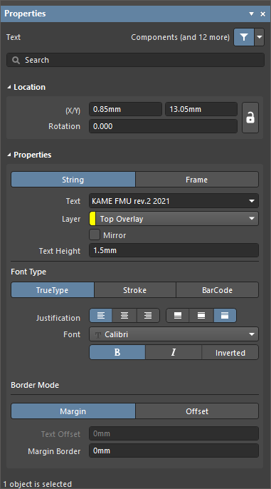
Properties
Location
の
Textモード この領域の右側にある

アイコンは、以下のフィールドにアクセスするために

(ロック解除)として表示されている必要があります。ロック/ロック解除アイコンを切り替えて、ロック状態を変更してください。
-
(X/Y)
-
X (第1フィールド)- 現在の設計空間原点に対する、テキストオブジェクトの基準点の現在のX(水平)座標。編集してテキストオブジェクトのX位置を変更します。値はメートル法/ヤード・ポンド法のいずれでも入力できます。現在の既定単位と異なる単位で入力する場合は、単位を付けて入力してください。
-
Y (第2フィールド)- 現在の原点に対する、テキストオブジェクトの基準点の現在のY(垂直)座標。編集してテキストオブジェクトのY位置を変更します。値はメートル法/ヤード・ポンド法のいずれでも入力できます。現在の既定単位と異なる単位で入力する場合は、単位を付けて入力してください。
-
Rotation - テキストオブジェクトの回転を指定します。最小角度分解能は0.001度です。
Properties
Font Type
-
TrueType- PC上で利用可能なフォント(\Windows\Fonts フォルダ内)を使用するように選択します。TrueTypeフォントはUnicodeを完全にサポートします。デフォルトでは、ソフトウェアは使用中のTrueTypeフォントにリンクします(PCBファイル内には保存されません)。そのため、設計を別のPCへ移動する場合、移動先の各PCにも同じフォントが存在している必要があります。別の方法として、PreferencesダイアログのPCB Editor - True Type Fontsページにあるオプションを使用して、使用中のTrueTypeフォントをPCBファイルに埋め込むことができます。ここでは、埋め込まれていないフォントが利用できない場合に使用するSubstitution Fontも選択できます。
-
Justification - これらのコントロールを使用して、テキストの水平および垂直方向の配置を設定します。
-
Font - ドロップダウンから目的のTrueTypeフォントを選択します。必要に応じて、B(太字)および/またはI(斜体)オプションを使用してテキストを強調します。
-
Inverted - 有効にすると、テキストを反転表示します。関連するWidth およびHeightフィールドが利用可能になり、テキスト周囲の枠のサイズを制御できます。
-
Stroke
-
Justification - これらのコントロールを使用して、テキストの水平および垂直方向の配置を設定します。
-
Font - ドロップダウンから目的のStrokeフォントを選択します。選択肢は次のとおりです。
-
Default - ペンプロッタおよびベクターフォトプロット向けに設計されたシンプルなベクターフォント。
-
Sans Serif - Gerberなどのベクター出力生成を遅くする複雑なフォント。
-
Serif - Gerberなどのベクター出力生成を遅くする複雑なフォント。
-
Stroke Width - ストローク幅を表示します。
-
Border Mode
-
BarCode - 次のいずれかのバーコードタイプを選択します。