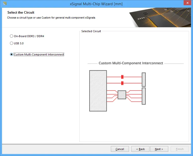
In this mode, the Wizard can be used to define multiple xSignals between a chosen source component and multiple target components. The wizard is configured over a number of pages. The number of pages depends on the circuit configuration, for example if there are series terminators then there are additional pages. The configuration of each page is described below.
Select the Source Component

On this page you select a single source component.
On this page you select a single source component. Use the component Filter and the Min Pin Count checker to help locate the component of interest. The * and ? wildcards are supported.
Click Next to continue.
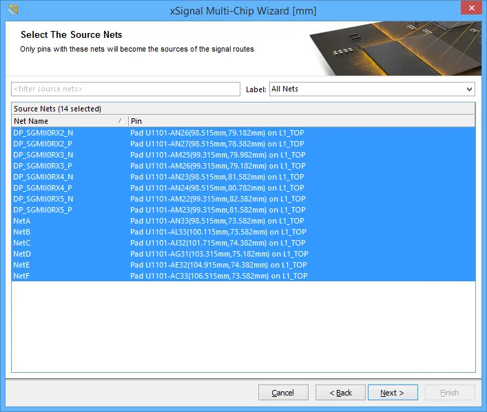
Select the Source Nets

Select the nets of interest connected to the chosen source component.
Select the nets of interest connected to the chosen source component. Use the Net and Net Class filters to help locate the nets of interest.
Click Next to continue.
Select Destination Components

Select the destination component(s) that you are interested in.
Select the destination component(s) that you are interested in. Use the component Filter and the Min Pin Count checker to help locate the component of interest.
When you click Next, the Wizard will identify all of the possible xSignals that can be created from the set of nets that have been selected, between the chosen components. If the Wizard detects 2-pin components that have both of their pins connected to the chosen nets, these are automatically identified as series termination components and extra Wizard pages will appear later in the process.
Click Next to continue.
xSignal Routes

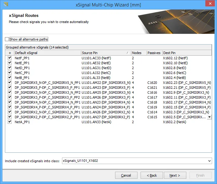
After analyzing the chosen nets running between the chosen pairs of pins, potential xSignals are presented.
This page of the Wizard will list the proposed xSignals from each Source Pin through to each Destination Pin, click on an entry to highlight that xSignal in the workspace.
After analyzing the net paths to identify potential xSignals, the Wizard will then attempt to reduce the set to only list combinations that the designer is interested in. These are the end-to-end xSignals, the image above shows them between the source and destination components selected in the previous page of the Wizard.
The image also shows also that the Wizard has detected series termination components, R1, R2 and R7. R7 is actually a resistor pack, in this situation the Wizard will automatically create logical associations, assuming that each resistor runs across the pack it will pair the nets that connect to pins that are opposite each other on the component.
Because this assumption that the pins of each resistor are opposite each other might not always be correct, the designer can select any of the other outgoing nets, using the dropdown in the Dest Pin column. Alternatively, enable the Show all alternative paths option at the top of the Wizard to display all of the potential combinations of nets that could be used to generate xSignals. Enable the checkbox for each line that you wish to create an xSignal for.
The lists in this Wizard include a right-click shortcuts menu and standard Windows multi-select keys are supported. You can also use left-click or the Spacebar to toggle the checkbox of selected items.
The enabled xSignals will be added to the xSignal class defined at the bottom of this page of the Wizard, enter a new name or select one from the existing xSignal classes.
Click Next to continue.
xSignals Length Tuning

This page of the Wizard is used to create an xSignal class and a suitable Matched Length design rule for this set of xSignals.
This page of the Wizard is used to automatically create a Matched Length design rule for the enabled xSignals. Enable only those xSignals you want to be targeted by this new design rule - if your design requires multiple rules with different requirements, you will be given the opportunity to define additional rules for those xSignals that have not yet had a rule defined, later in the process. This first stage will also present the overall end-to-end xSignals - in future Wizard pages you will have the opportunity to define design rules for the sections within the xSignals, for example for the output pin to series termination resistor sections.
The xSignal Class Base Name field is used to define a name for the currently selected xSignals, enter a meaningful name, keeping in mind that you may be repeating this process for other xSignals. This set of xSignals will then be targeted by a design rule of the name you enter into the Matched Lengths Rule Base Name field, with the specified Length Tolerance.
Click Next to continue.
Not sure which objects are being targeted? click on one or more entries to highlight the signal path(s) in the workspace.
Source to Passives Length Tuning

Extra Wizard pages are presented when there are series termination components.
If the set of nets selected include series termination components extra Wizard pages will appear, giving the designer the opportunity to create additional xSignals and design rules for these sections of the nets. In the image above you can see that this page of the Wizard is being used to create a Matched Length design rule for the chosen xSignals that run from the Source pins to the termination components. If you require xSignals / an xSignal class / a design rule for these click then Yes, I want these segments to have the same length radio button, enable the required xSignals, and define the Class Name, Rule Name and Tolerance. Additional xSignals will be created to use with this Matched Length rule.
Click Next to continue.
Passives to Destinations Length Tuning

A second additional Wizard page is used to define the xSignals on the other side of the termination components.
This page of the Wizard is used to create a Matched Length design rule for the chosen xSignals that run from the termination components to the Destination pins. If this is required click the Yes, I want these segments to have the same length radio button, enable the required xSignals, and define the Class Name, Rule Name and Tolerance. Additional xSignals will be created to use with this Matched Length rule.
Click Next to continue.
Report and Continue

A summary of the xSignals and rules about to be created, along with an option to continue to create additional xSignals.
This page of the Wizard will detail:
- the number of xSignals about to be created, and
- the number of design rules about to be created.
At the bottom of the page you can choose to:
- continue length tuning for created signals - select this option if you disabled specific xSignals on previous pages and now need to go through the process of defining additional rules for those xSignals
- Restart Wizard for the same source component - select this option if you want to discard these settings and restart the Wizard with the same components/nets selected
- Finish Wizard - select this option if you are finished with this source component's xSignal and design rule creation.
xSignals are detailed in the xSignal mode of the PCB panel, press the Delete key to remove selected xSignal classes or selected xSignals.
These xSignals are ready for length tuning, right-click on a net in the workspace or the xSignals mode of the PCB panel and select Interactive Tuning to get started.
You can easily remove a length tuning accordion, click once on any segment in the accordion to select it, then press Delete.
Note that the existing track segments are broken at the start and end points when you place an accordion, so if you repeat this tune-then-delete process a few times you can end up with a straight stretch of routing that is actually made up of many short track segments. To resolve multiple small track segments back into a single segment, run the Design » Netlist » Clean All Nets command.
