Applied Parameters: ShowInBoardPlanner=1
Summary
A common feature on rigid-flex boards is the selective use of coverlay material. This insulation layer is cut and laminated onto specific areas of the board (Board Regions), and because of this selective use, custom coverlay is often referred to as bikini coverlay. As well as its use in specific areas of the board, custom coverlay can also be positioned anywhere in the layer stack. Custom coverlay is added in the Layer Stack Manager dialog and the shape manipulated in the workspace in Board Planning Mode, once the Custom Coverlays option is enabled in the Board Region dialog for the required region of the board.
This command is used to place a Coverlay Cutout within the active board design. In reality, what you are placing is a Region object on a coverlay layer, whose Kind is set to Polygon Cutout. This allows you to further customize a coverlay, by creating a cutout (a void) within a Coverlay Polygon object.
Access
This command can be accessed from the PCB Editor, when configured in Board Planning Mode. Ensure that the required coverlay layer is the active layer in the main workspace, then choose the Design » Place Coverlay Cutout command, from the main menus.
The current viewing mode for the PCB document can be changed using the corresponding commands from the main View menu. To switch to Board Planning Mode, use the command of the same name, or use the 1 keyboard shortcut.
Use
After launching the command, the cursor will change to a cross-hair and you will enter region placement mode. Placement is made by performing the following sequence of actions:
- Position the cursor and click to anchor the starting vertex for the region.
- Move the cursor ready to place the second vertex. The default behavior is to place 2 edges with each click, with a user-defined corner shape between them. Refer to the Placement Modes topic below for more details on changing corner modes.
- Continue to move the mouse and click to place further vertices.
- After placing the final vertex, right-click or press Esc to close and complete placement of the region. There is no need to manually close the region as the software will automatically complete the shape by connecting the start point to the final point placed.
- Continue placing further regions, or right-click or press Esc to exit placement mode.
Press the Tab key to access the Region dialog, from where properties for the region can be changed on-the-fly. The Kind property is fixed when placing a coverlay cutout using this command, but you can change coverlay layer (top or bottom side) and lock the object.
While attributes can be modified during placement (Tab to bring up associated properties dialog), bear in mind that these will become the default settings for further placement unless the Permanent option on the PCB Editor – Defaults page of the Preferences dialog is enabled. When this option is enabled, changes made will affect only the object being placed and subsequent objects placed during the same placement session.
Placement Modes
When defining the shape of the region, there are 5 available corner modes, 4 of which also have corner direction sub-modes. During definition:
- Press Shift+Spacebar to cycle through the 5 available corner modes: 45 degree, 45 degree with arc, 90 degree, 90 degree with arc, and Any Angle.
- Press Spacebar to toggle between the two corner direction sub-modes.
- When in either of the arc corner modes, hold the
 or
or  keys to shrink or grow the arc. Hold the Shift key as you press to accelerate arc resizing.
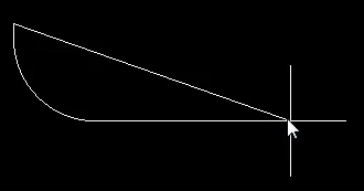
- Press the 1 shortcut key to toggle between placing 2 edges per click, or one edge per click. In this second mode the dashed edge is referred to as the look-ahead segment (as shown in the last image in the set below).
- Press the Backspace key to remove the last vertex.


Press Shift+Spacebar to cycle through the 5 available corner modes, press the 1 shortcut to toggle placement between 2 edges or 1 edge.
Tips
- Coverlay is automatically added to cover the entire area of the board region is was added to. Behaving like an additional solder mask layer, openings are automatically created for component pads in accordance with the applicable Solder Mask Expansion design rule, or else the settings in the Pad dialog if the Solder Mask Expansions setting has been configured to override the design rule. The automatic coverlay is formed as a polygonal object, it can be selected and reshaped (or deleted) as required.
- To add your own custom coverlay area, place a Coverlay Polygon using the Design » Place Coverlay Polygon command, from the main menus.
- User-defined coverlay changes, such as modifying the shape of the automatic coverlay, or placing additional coverlay objects, are removed if the Custom Coverlays option is turned off in the Board Region dialog, for the applicable board region.
- Custom Coverlay is a mask layer, behaving as an additional Solder Mask layer. Solder Mask layers normally display and output as a negative, that is, the objects you see on the screen become holes in the fabricated mask layer. The on-screen presentation of Solder Mask can be configured to display as a positive, if preferred (and therefore also the coverlays).
- In standard 2D display mode, the custom coverlay is shown as if it was on the top/bottom solder mask - this is simply a display feature, when output is generated the top solder mask and the top custom coverlay are written out as separate data, as are the bottom solder mask and bottom custom coverlay.
