New in Altium On-Prem Enterprise Server
Released: 4 June 2024 - Version: 6.0.7 (build 13)
Released: 6 May 2024 - Version: 6.0.6 (build 4)
Released: 25 January 2024 - Version: 6.0.5 (build 28)
Released: 22 December 2023 - Version: 6.0.5 (build 26)
Released: 29 September 2023 - Version: 6.0.4 (build 17)
Released: 16 August 2023 - Version: 6.0.3 (build 3)
Released: 6 July 2023 - Version: 6.0.2 (build 15)
Released: 3 April 2023 - Version: 6.0.1 (build 33)
Release Notes for Altium On-Prem Enterprise Server 6.0
This major release delivers a large number of new features and upgrades to the Altium On-Prem Enterprise Server Workspace interface. In addition, numerous fixes have been made to resolve issues raised by customers through the AltiumLive Community.
Enterprise Server Installation
This update was introduced in Altium Enterprise Server version 6.0.4
The Altium Enterprise Server has been upgraded from the use of Microsoft .NET Core 3.1 services to .NET 6 services. To maintain compatibility with other software, the existing .NET 3.1 software framework will not be removed during the Enterprise Server's installation/update but can be manually removed via Windows' Control Panel if required.
New PLM Configuration Interface
The Altium Enterprise Server's connection to a supported PLM system can now be configured through an advanced new graphical user interface (GUI). While the previous PLM connection process required manual editing of XML files and knowledge of the target PLM system, the revised GUI offers menu-based type and attribute mapping options based on data automatically sourced from both the Server and the PLM system.
The new PLM configuration GUI and process is invoked from the ![]() button under Admin – PLM Integration. Once your PLM connection is established the system will load and populate the relevant type and parameter/attribute options. The synchronization direction for component types is also a simple menu choice, and further setup options are made available based on the type of connected PLM.
button under Admin – PLM Integration. Once your PLM connection is established the system will load and populate the relevant type and parameter/attribute options. The synchronization direction for component types is also a simple menu choice, and further setup options are made available based on the type of connected PLM.
 The new configuration GUI setup for the parameter mapping and synchronization of Capacitor type parts from an Aras PLM to the Enterprise Server
- The PLM connection and configuration is automatically validated. Any errors are trapped and highlighted in red.
-
Use the
 button to complete the configuration process.
- The interface can be reverted to the previous system by unchecking the Enable new PLM Configuration page under Admin – Settings - PLM Integration.
- Only one type of the PLM interface should be used (old or new). Do not edit a PLM configuration that was created by a different version of the interface.
- See PLM Integration for information on working with a PLM system.
PLM and Workflow Related Updates
These updates were introduced in Altium Enterprise Server version 6.0.4
-
Teamcenter: Teamcenter® PLM integration now inherently supports the bidirectional synchronization of manufacturer Part Choices between the Altium Enterprise Server and the Teamcenter PLM instance. Component Part Choice data (
Manufacturer Part NumberandManufacturer) on the Altium side can be directly synchronized with 'native' Manufacturer Part and Vendor parameters on the Teamcenter side, which are available when Teamcenter's Vendor Management features are enabled.
-
Arena: Arena® PLM integration now includes configuration options for targeting an Arena direct or indirect part sourcing relationship for Part Choice data synchronization. Part sourcing information in Arena is primarily held as Vendor parameters with a secondary relationship of Manufacturer parameters. When specifying Part Choices options in your Arena configuration, the Part Choice Information drop-down menu options are:
-
Native PLM Manufacturer Parts: Direct Source Relationship – choose this option to target Altium Part Choice data to Arena's Vendor sourcing relationship data. This is the previous default condition, so any existing
ToPLMsynchronization events will have targeted the Vendor relationship. - Native PLM Manufacturer Parts: Indirect Source Relationship – choose this option to target Altium Part Choice data to Arena's Manufacturer sourcing relationship data. Altium Part manufacturer data will then correlate to manufacturer data entries on the PLM side.
-
PLM Part Attributes (unchanged) – choose this option to set up 'non-native' Part Choice synchronization based on conventional component parameter data formed by sets of
Manufacturer:PartNumberattributes, as selected using the associated Attribute Definitions.
-
Native PLM Manufacturer Parts: Direct Source Relationship – choose this option to target Altium Part Choice data to Arena's Vendor sourcing relationship data. This is the previous default condition, so any existing
- Generic Connector: The Enterprise Server's PLM Integration system choices have been expanded to include a new Generic Connector PLM driver. Available for selection in the Driver menu under PLM Connection, this driver is a PLM-agnostic configuration structure that can be used by third parties to implement a connection and interface for any PLM system. An example of this is Duro PLM support in an Altium 365 Workspace.
- Component Creation: Part Choices associated with a PLM Part Request workflow, or Part Choices associated with project components in a Publish to PLM workflow, are now added to the target PLM system along with the created component object. The Part Choice data is propagated to the new PLM part as Vendor/Manufacturer sourcing entries, as is the case when components are synchronized to PLM.
-
Workflow Title: Administrators are now able to lock the Title field of a Process Workflow to ensure naming consistency across active and completed process tasks. This option is controlled by a new 'Allow the initiator to change the process title' checkbox option that is available in the Properties pane when editing a Process Workflow. When this option is unchecked (and the Process saved), a user that activates the Workflow (the
Initiator) cannot edit its Title, which remains locked as 'AUTO'. Such active or completed processes will be titled by the Process name with a sequential number suffix –<process name> #1,<process name> #2, etc.
Updated BOM View
The Enterprise Server's project BOM View now makes full use of the data provided by an ActiveBOM document that is included in the current project. Generated within Altium Designer, the project's ActiveBOM document provides a rich set of live manufacturer and supplier part information that is integrated into the Workspace BOM view. This includes supplier Part Choices (with current pricing and stock information), part manufacturer lifecycle status and datasheet links, and more.
Icon-based validity checks are also available for each BOM entry, which indicate part issues such as an out-of-date revision, an Obsolete lifecycle state, or insufficient supplier stock. In line with other document views Commenting is now supported, which allows users to place a comment note on any BOM item entry and optionally assign it to a user or group. As in the previous version of the BOM view, you can cross-probe to other project documents, enable the data columns to suit your needs , and select a component to view its (now enhanced) details in the information pane on the right.
Web Viewer Improvements
A large number of improvements and additions have been made to the server's Web Viewer to further extend its value for project designers and other team members. These increase the project design data made available through the viewer and provide additional flexibility in how design documents can be viewed.
Net-Schematic Navigation
When a Net is selected in the view it is also selected in all schematic documents on which it appears, which are now listed in the Information panel on the right. Click on an entry in the list to navigate directly to that document.
Set Active Layer
Each layer entry in the Layers/Objects pane now has an associated checkbox that will set it as the active layer. When checked, the layer is set to the top of the draw order and is therefore rendered last so that it effectively overlays the other PCB layer graphics. Uncheck an active layer or use the upper ![]() button to restore the default layer view (Top layer active).
button to restore the default layer view (Top layer active).
Note also that a placed Comment will be associated with the currently selected (checked) layer, and that same layer order is restored when the Comment is subsequently selected.
Layer Visibility Control
Layer entries in the Layer/Objects pane (in Layers mode) now have additional visibility options, which are exposed when hovering on the entry. Use the ![]() icon to toggle the visibility of a layer, the
icon to toggle the visibility of a layer, the ![]() option to enable only that layer (and by default,
option to enable only that layer (and by default, Multi-layer objects for copper/mask layers), and the ![]() icon to restore the visibility settings.
icon to restore the visibility settings.
Object Visibility Control
In a similar manner to Layer visibility (above), the visibility of PCB objects can now be set in the Objects mode of the Layers/Objects pane. Use the ![]() and
and ![]() options associated with an object type entry in the pane to specify its visibility, and the
options associated with an object type entry in the pane to specify its visibility, and the ![]() option to reset the settings.
option to reset the settings.
Note that Connection lines (ratsnest) is available as a selectable object, and object visibility selection is also available in 3D view. The 2 and 3 shortcut keys will now switch between the 2D and 3D views.
Web Viewer Settings Retention
Current Web Viewer settings such as the open document, PCB Layer/Object visibility, zoom level, window position, and Variant selection now form part of the browser's URL context. This means that the settings are retained when the browser is refreshed (say, to register a new Commit), and also when the URL is copied to a different window or passed to another user.
Double-click Net Selection
An entire net can now be selected in the PCB view by double-clicking on an object such as a track, pad, via, etc. Individual clicks will cycle through the objects under the cursor, as before.
View Multiple PCB Documents
The Web Viewer now fully supports projects that contain multiple PCB documents, including PCB panels. When a PCB document is selected for display, the Web Viewer's associated features will relate to the selected board layout wherever possible, and otherwise default to the primary PCB (the first one found in the project structure). Placed Comments will be associated with the board layout, and features such as Net navigation, cross-probing, layer Stackup View, measurements, and Information pane data will all apply to the opened PCB document.
Additional Document Views
This release of the Altium Enterprise Server delivers expanded viewer and data information support for important manufacturing-related design document files.
Draftsman View
The Web Viewer provides access to project Draftsman documents through both the navigation tree on the left and the viewer's dedicated ![]() tab. The view supports multi-page Draftsman documents – navigated via the Page dropdown menu – and document Commenting. While the viewer tab will open the first Draftsman document found in the project structure, other Draftsman documents can be opened directly from the navigation tree.
tab. The view supports multi-page Draftsman documents – navigated via the Page dropdown menu – and document Commenting. While the viewer tab will open the first Draftsman document found in the project structure, other Draftsman documents can be opened directly from the navigation tree.
Note that the Draftsman document view is also supported in the Design Snapshot of an opened project Release.
PDF View
Support is now included for viewing PDF documents directly in the Web Viewer. While previously available for download only, PDF documents in a design project – such as those available in the Files section of a project Release package – will open a dedicated PDF viewer when selected in the navigation tree. Use the Page dropdown menu (or simply scroll) to move the view to another page in a multi-page PDF document, and the Information pane on the right to access the PDF document metadata.
Design Data Comparisons
The ability to easily perform comparisons between previous and current design documents delivers substantial benefits to the design tracking and review process. The Altium Enterprise Server now provides visual-based data comparisons between old/new versions of Gerber, Schematic, and BOM document data.
Design Data Comparisons are available from:
-
The History view – use a tile's
 menu options to compare between Releases, between Commits, or between Releases and Commits. You can choose the previous Commit/Release or a selected Commit/Release. A Gerber comparison is available with Releases only.
-
The Releases view – use a tile's
 menu options to compare between adjacent or selected Release events.
Schematic Comparison
Choose the Schematic to option and a target Release/Commit to invoke a schematic data comparison between the two events. The differences engine will detect the changed data and present the results in a dedicated Schematic Compare view, which highlights the differences graphically and as interactive data references in the Differences pane.
The schematic Component and Net changes are color highlighted as green (added), red (removed), and yellow (modified). Select an entry in the Differences pane to cross-probe to the schematic, the entry's sub-entries to see further detail, and the ![]() icon to view related schematic documents.
icon to view related schematic documents.
► See Schematic Comparisons to learn more.
Gerber Comparison
Choose the Gerber to option and a target Release to invoke a Gerber data comparison between the two events. The differences engine will detect the changed data and present the results in a dedicated Gerber Compare view, which highlights the differences graphically and as interactive data references in the Differences pane.
The Gerber layout changes are numbered, grouped by layers, and color highlighted as green (added), red (removed), and yellow (modified). Select an entry in the Differences pane to cross-probe to the Gerber view, and upper view tabs switch the Gerber view to either of the compared data sets – effectively the old or new Gebers layouts.
Note that the Gerber Comparison view also allows you to make multiple measurements between any two points within the view. Use the ![]() button to invoke the measurement mode and open the Measurements pane.
button to invoke the measurement mode and open the Measurements pane.
► See Gerber Comparisons in Altium 365 to learn more.
BOM Comparison
Choose the BOM to option and a target Release/Commit to invoke a BOM data comparison between the two events. The differences engine will detect the changed data and present the results in a dedicated BOM Compare view, which lists the differences as highlighted BOM entries.
The BOM entry column elements are color highlighted as green (added), red (removed) and yellow (modified). Use the checkboxes in the pane on the left to limit the BOM differences listing to specific change types (Added, Removed, etc), the columns dropdown menu to enable/disable the inclusion of specific component parameter data columns, and the upper view tabs switch the BOM view to either of the compared data sets – effectively the old or new BOM listing.
Note that you can download a BOM comparison summary in CSV format from the ![]() icon at the top.
icon at the top.
► See BOM Comparisons to learn more.
Transfer Project Ownership
Adding a further level of control to the access management of Enterprise Server design projects is the introduction of project ownership transfer. This allows Workspace administrators or the current owner of a project – typically the user that created the project – to specify another Workspace user as the new owner. The transfer is performed through the project Share window, where the intended new owner must be present with current Edit/View access rights.
Perform the ownership change by selecting the Make Owner option from the user's permissions dropdown menu, click ![]() to confirm, and then
to confirm, and then ![]() to acknowledge the following information window. The new owner will receive full control and editing rights to the project, and the previous owner's access will revert to an
to acknowledge the following information window. The new owner will receive full control and editing rights to the project, and the previous owner's access will revert to an Edit permission status. If the server's Email Notifications are enabled, the new project Owner will receive an ownership transfer notification email.
The transfer of ownership process also is invoked if a user who owns a project (or projects) is removed from the Workspace. In this case the administrator specifies a new project owner that will adopt the removed user's access rights to the project (the Owner status).
Commit Tags
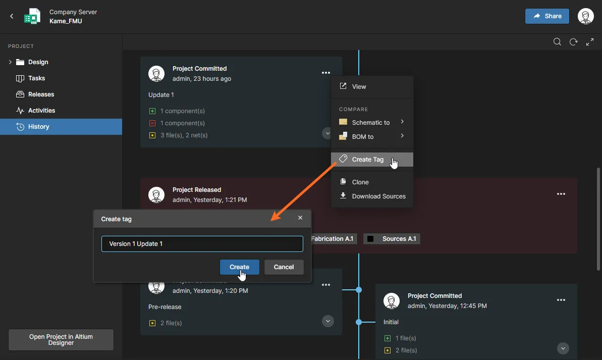
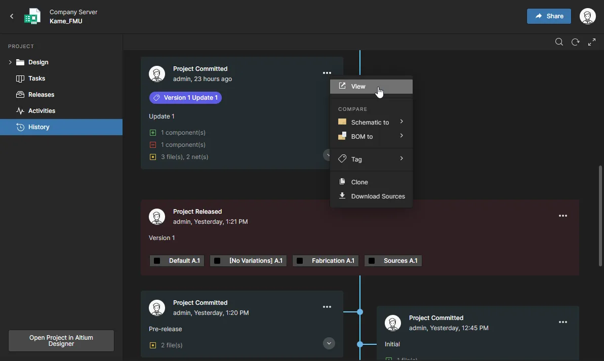
You are now able to add a VCS tag name to the currently selected Commit event in the Workspace History view – select the Create Tag option from the tile's ![]() dropdown menu. An existing Tag can be edited or removed from the same dropdown menu.
dropdown menu. An existing Tag can be edited or removed from the same dropdown menu.
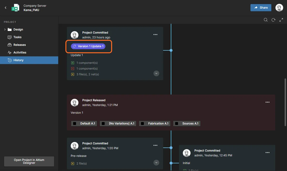
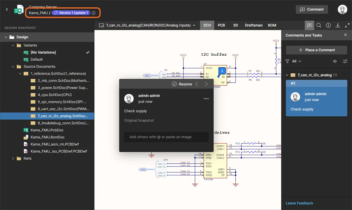
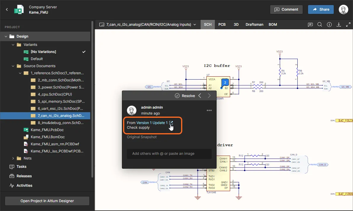
A Tag attached to a commit appears in its History tile, in the header of the commit's snapshot view, and in any Comments attached to that snapshot view. Such a comment will also be visible in the project's current WIP view and include a link to the related commit snapshot view.
New Feature Admin Settings
Additional options that relate to new Enterprise Server features are available to Administrators in the Admin – Settings area:
- Email Notifications – Check the Send a notification when no updates have been made to a workflow task option to enable email reminder notifications for those that have a pending Process Task assigned to them. The server's Send Mail must be configured and enabled for Task reminders to be sent.
- Components – Enable the Part Choices Revision Control option to impose formal control of Part Choices List changes in Altium Designer, which will then open the Component Editor in response to a Part Choice update so a new revision will be created. See Part Choice Revision Control in Altium Designer for more information.
- PLM Integration – Uncheck the Enable new PLM page option to revert the PLM interface to its former version. Note that PLM Configurations should be created/edited using one version of the interface only – the old or the new.
Lightweight Tasks
The Tasks feature and view In the Altium Enterprise Server has been significantly expanded to incorporate the new concept of Lightweight Tasks – job activity requests generated by Comment user assignments. Both the existing Tasks created by process workflows and the new Lightweight Tasks are presented in a revised Tasks view that uses a Kanban-style board flow with defined progress states. Although presented through a relatively simple interface, the new Tasks dashboard offers a flexible and efficient way of both managing and tracking workflows within the actual design environment rather than via an external system.
The Tasks view is available at two levels:
-
At a global overview level – This Tasks view is accessed from the main Workspace navigation tree and shows all active Tasks within the Workspace. Project-specific Tasks are arranged in project rows, and also included is a general Tasks row for Workspace Tasks that do not relate to a project – general Tasks are created from the
 control.
- At a project level – This Tasks view is accessed from the navigation tree of an open project and shows active Tasks that relate to that project. Tasks rows are arranged by document-specific Tasks and workflow Tasks, along with a general Tasks row for project Tasks that do not relate to a specific document.
Select a tile to view its details and change its progress status, user assignment, and priority level. A process workflow tile will open its related task in the workflow, which can be completed by the user it is assigned to.
► See Working with Tasks in Altium 365 for related information.


