Parent page: Workspace Content Types
Altium NEXUS, in conjunction with your connected Workspace, caters for the ability to create and manage 3D models (3D Model Items) in that Workspace. Used in a similar fashion to file-based linked 3D models, a 3D Model Item can hold a 3D model file, that is then referenced through a 3D body attached to a standard 2D footprint. Once a 3D model has been created within the Workspace (and data uploaded into a revision of it), it can be reused in future board-level design projects.
Folder Type
When creating the folder in which to store 3D models, you can specify the folder's type. This has no bearing on the content of the folder – uploading will always result in a 3D Model Item. It simply provides a visual 'clue' as to what is stored in a folder and can be beneficial when browsing a Workspace for particular content. To nominate a folder's use as a container for 3D model, set its Folder Type as 3D Models, when defining the folder properties in the Edit Folder dialog.
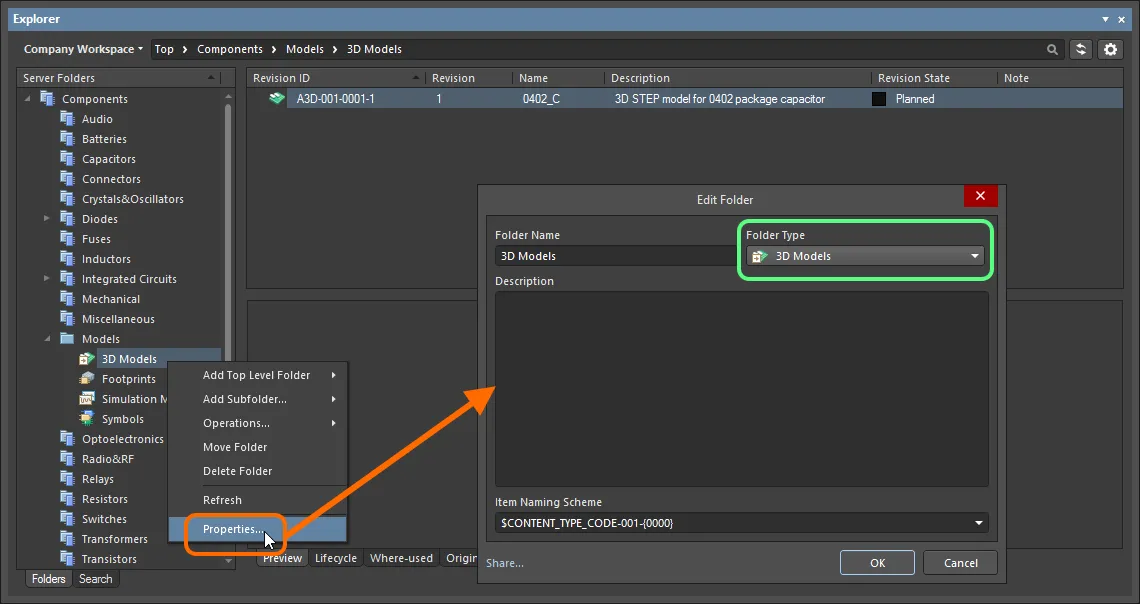
Specifying the folder type – its intended use – gives a visual indication of the content of that folder when browsing the Workspace.
Item Naming Scheme
Another important aspect of the parent folder is the Item Naming Scheme employed for it. This defines the format of the unique ID for each Item created in that particular folder. Several default example schemes are available, utilizing the short-form code for either the folder type (A3DL – Altium 3D Library) or the content type (A3D – Altium 3D):
$CONTENT_TYPE_CODE-001-{0000} – for example, A3D-001-0001.$CONTENT_TYPE_CODE-001-{A00} – for example, A3D-001-A01.$FOLDER_TYPE_CODE-001-{0000} – for example, A3DL-001-0001.$FOLDER_TYPE_CODE-001-{A000} – for example, A3DL-001-A001.
Using a default naming scheme, the software will automatically assign the next available unique ID, based on that scheme, having scanned the entire Workspace and identifiers of existing content. This can be a great time-saver when manually creating 3D models.
A custom scheme can also be defined for a folder by typing it within the field, ensuring that the variable portion is enclosed in curly braces (e.g. STEP3D-001-{0000}).
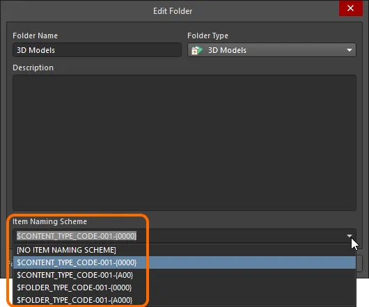
The Item Naming Scheme of the parent folder is applied to the Unique ID for each Item created within that folder.
The Item Naming Scheme employed for the parent folder can be changed at any time. The modified scheme will then be applied to any subsequent newly-created content within that folder.
Content Type
When creating the target 3D Model Item in which to store your 3D model file, ensure that its Content Type is set to 3D Model, in the Create New Item dialog. If you are creating the Item in a 3D Models type folder, this content type will be available from the right-click context menu when creating the Item.
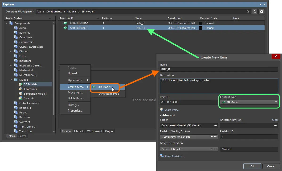
Creating a 3D Model Item within a 3D Models folder – the correct Content Type is available on the context menu.
Item Lifecycle Definition and Revision Naming
When defining the 3D Model Item, to which the source 3D model file is uploaded, be sure to specify the type of lifecycle management to be used for the 3D model, and the naming scheme employed for its revisions, respectively.
Control over which content types can use a particular lifecycle definition or revision naming scheme, can be defined and enabled at a global level from within the Content Types dialog, when defining each schema. The default schemes assigned for use by a 3D model are: Generic Lifecycle and 1-Level Revision Scheme, respectively.
Once a 3D model file has been uploaded into the initial revision of a 3D Model Item, these schemes cannot be changed for that particular Item.
Specify the required schemes in the Create New Item dialog, using the Lifecycle Definition and Revision Naming Scheme fields respectively.
If the option to control use of lifecycle definitions and revision naming schemes per content type is enabled for any definitions/schemes, and the 3D Model content type is not set to use a particular definition/scheme, then that definition/scheme will not be available in the applicable drop-down list.

Selecting the Lifecycle Definition and Revision Naming schemes for a manually created 3D model.
Observing standard revision naming schemes and lifecycle definitions, across the various types of design content in a Workspace ensures smooth, consistent management of this content.
It is a good idea to add a Name and Description as part of the 3D model's definition. This information is used when searching the Workspace and enables quick identification of what a 3D model offers.
Uploading a 3D Model File
So far, we've discussed the support for a 3D model in the Workspace, in terms of related folder and content types. Uploading a 3D model file into a revision of a 3D Model Item can be performed in a couple of ways.
Upload Menu
A 3D model file can be uploaded by right-clicking on the required 3D Model Item in the Explorer panel, and choosing the Upload command from the context menu. The Create New Revision dialog will appear, in which you can change Name, Description, and add release notes as required. Use the Sources region of the dialog to load the required model file. This can be performed by dragging and dropping the file from Windows Explorer, onto the region. Alternatively, click the  button – the Add Files dialog (a standard Windows open-type dialog) will appear. Use this to browse to, and open, the required model file.
Supported formats are:
- STEP File (
*.step; *.stp)
- Parasolid File (
*.x_t; *.x_b)
- SolidWorks Part File (
*.sldprt)
If the Item has no planned revision, upload will be to the next planned revision, created on-the-fly as part of the upload process.

Manually specifying the 3D model file to be uploaded to the target 3D Model Item.
Once the desired file is dropped in, or selected and the Open button clicked, an entry for it will appear back in the Sources region. Proceed with the upload by clicking the OK button. The graphical depiction of the uploaded model can be viewed on the Preview aspect view tab for the Item Revision, in the Explorer panel.

Browse the saved revision of the 3D Model Item, back in the Explorer panel. Switch to the Preview aspect view tab to see its graphical depiction.
Drag and Drop from Windows Explorer
A 3D model file can also be uploaded by dragging the selected file from a source folder in your Windows Explorer, and dropping onto the required target 3D Model Item in the Explorer panel. The Create New Revision dialog will appear, with the dragged file listed in the Sources region. Add any Release Notes as required, and then click the OK button.

Uploading a 3D model using the drag and drop method.
If the existing 3D Model Item has no planned revision, upload will be to the next planned revision, created on-the-fly as part of the upload process. If you drop the dragged model away from an existing Item, a new 3D Model Item will be created. The
Create New Item dialog will appear. The
Name of the item will be the file name. The
Description will be the file name (with extension). Change these as required. The
Item ID will be in accordance with the Item Naming scheme defined at the folder level. If the folder has no naming scheme defined, naming will follow the
$CONTENT_TYPE_CODE-{000000} scheme.
If you attempt to drag and drop more than one 3D Model file, the
Release Manager dialog will automatically launch. Use this to complete upload of multiple models.
Reusing a 3D Model
Related page: Controlling Access to Workspace Content
Once a 3D model file has been uploaded to a Workspace, and its lifecycle state set to a level that the organization views as ready for use at the design level, and its lifecycle state set to a level that the organization views as ready for use at the design level, that 3D model can be reused in future board-level design projects.
A 3D body is used to provide the three-dimensional representation of the component in the PCB domain, and is typically placed and defined in conjunction with the standard 2D footprint model, when defining that footprint model (which is then saved to the Workspace as a revision of a target footprint).
The quickest, and easiest way to use a revision of a 3D model, is to place it directly from the Workspace into a PCB or PCB Library document, creating a 3D Body object that references that revision. The 3D Body object can then be fine-tuned as required. To place:
- Ensure a PCB Library (or PCB) document is open as the active design document.
- Drag and drop the required revision of the 3D model (from the Explorer panel) into the document design space. Alternatively, right-click on the required revision of the 3D model and choose the Place command from the context menu.
Drag and drop (or right-click and Place) the top-level entry for an Item itself, to place an instance of the latest revision of that Item.
Conversely, if you are defining the 3D Body object, and want to reference a 3D model that is stored in a Workspace, this can be done from within the Properties panel, when defining the properties for the body.
To do so:
- In the 3D Model Type region of the panel, choose the Generic option.
- In the Source region of the panel, choose the Server option.
- Click the
 button to the right of the Item Revision field. This gives access to the Choose Item dialog (essentially an incarnation of the Explorer panel). Use this dialog to browse to, and select, the revision of the required 3D model. After clicking OK, a link will be created between the 3D Body and the target revision of the 3D Model Item. Evidence of this link can be seen back in the Properties panel. Note that the Identifier field for the 3D Body will be filled with the Item-Revision ID of the linked 3D Model Item.
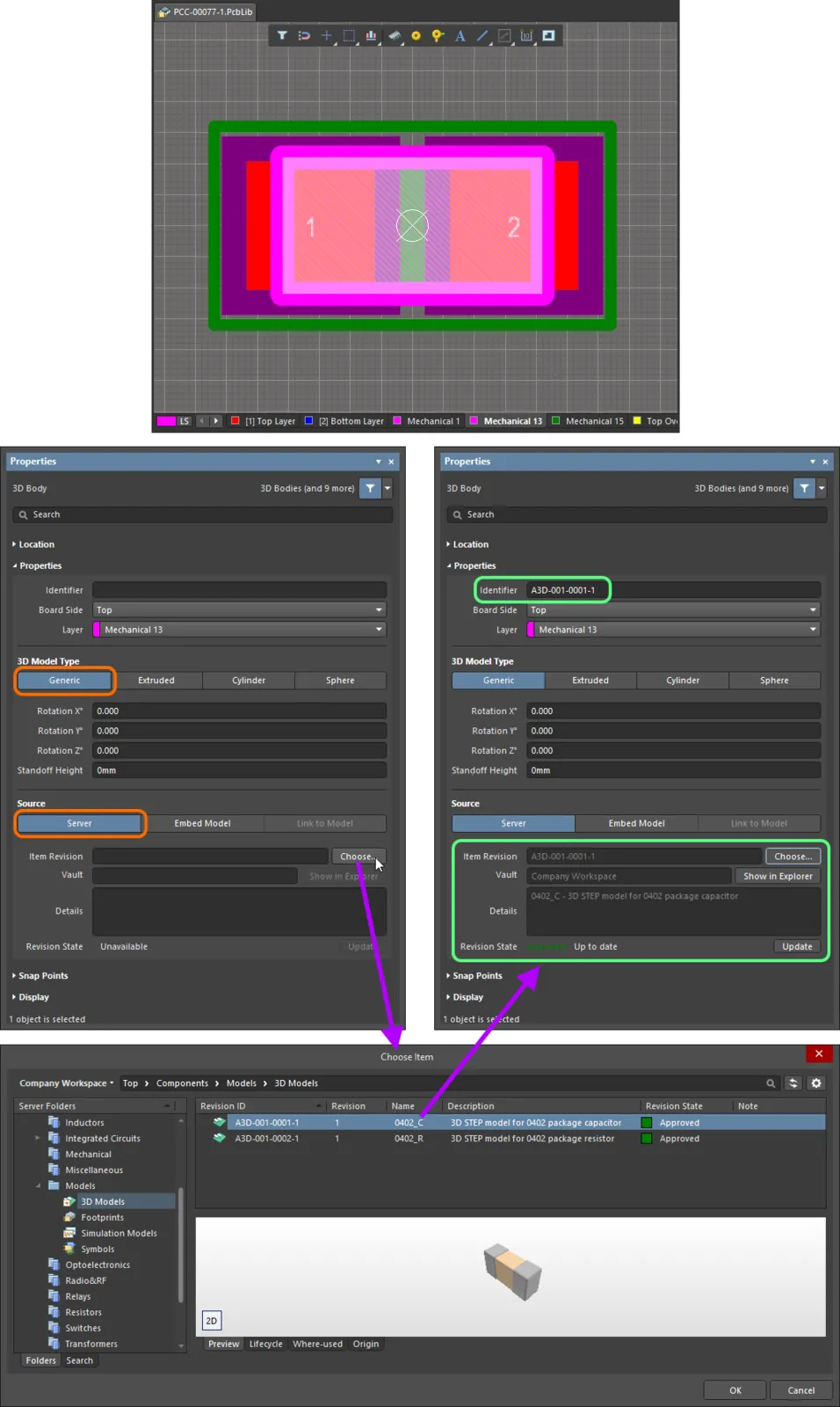
Manually linking a 3D Body object to a revision of a 3D Model Item, in the target Workspace.
The 3D Model Item being used can be changed at any time – click

and select a revision of a different 3D Model Item.
The status of the linked 3D Model Item is reflected on the
Properties panel. If a newer revision of the linked Item is available, click the

button, to use that latest revision.
Saving a PCB 2D/3D Component Model into the Workspace
When directly editing the source 2D footprint model stored within a revision of a footprint – within a temporary PCB Library Editor – you can define a 3D Body object for it, with that body referencing (linked to) a revision of a 3D Model Item in a Workspace. The following happens upon saving of that footprint model:
-
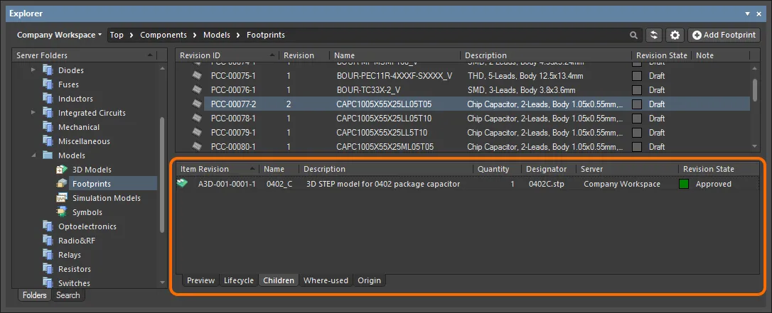
The 3D Model link is detected and the revision of the 3D model will appear listed as a child Item of the footprint, in its Children aspect view.
-
The revision of the 3D model is detected as 'being used' and will therefore list the parent footprint in its Where-used aspect view.

Updating a 3D Model
If you need to change the 3D model stored in a 3D Model Item, upload the required new model to that Item – the new model will be stored in the next revision of that Item.
Updating Related Footprints
When you make a change to a 3D model, the moment you upload that change into a new revision of the 3D Model Item, any footprints that use that model will become effectively out of date, still using the previous revision. In most cases, you will no doubt want to re-save those footprints, with the respective model links updated to use the latest revision available. To streamline this process your Workspace, in conjunction with Altium NEXUS, facilitates the ability to update related footprints – at the point of uploading to the latest revision of the 3D model.
Once uploaded, if any footprints currently reference the 3D model, a dialog will appear asking whether or not you wish to update those footprints.
If you want to keep all related footprints using the current revision of the 3D model, click No in the dialog. Only the model itself will then be uploaded.
A PCB Library document is then opened in its associated temporary editor (for direct editing). When multiple footprints use the 3D model, rather than separate instances of PCB Libraries being opened, a single PcbLib document is presented, containing all affected PCB 2D/3D component models.
The revision of the referenced 3D model is not updated to the latest automatically – you will need to do this manually, if required, from the
Properties panel.
Once the 3D body for a model is updated to reference the latest revision of the 3D Model Item (where needed), click the  /
/ button (on the Quick Access Bar, or from the PCB Lib Standard toolbar) or select the Save to Server command from the main menus (shortcut: Ctrl+Alt+S), to save the modified model(s) into new revision(s) of the corresponding footprint(s), back in the target Workspace:
- If only a single footprint revision is affected, the Edit Revision dialog will appear. Change Name, Description, and add release notes as required. After clicking OK, the save will proceed, and the temporary PCB Library editor then closed.
- If multiple footprint revisions are affected, the Edit footprints dialog will appear. This lists all footprint revisions that are scheduled to be saved. Add release notes as required. After clicking OK, the save will proceed, and the temporary PCB Library editor then closed.
As part of the re-saving of the footprint(s), you will also have the opportunity to update any parent component(s) – this is performed automatically if the option to update is left enabled.
Downloading a 3D Model File
Download the 3D model file stored in a revision of a 3D model, by right-clicking on that revision (in the Explorer panel) and choosing the Operations » Download command from the context menu. The file will be downloaded into a sub-folder under the chosen directory, named using the Item Revision ID. The file can be found in the Released folder therein.
Access the Download command from the top-level entry for a 3D model itself, to download the 3D model file stored in the latest revision of that model.
Click the Explore button in the Download from Server dialog, to quickly explore to the download folder.
Soft Deletion
When connected to a Workspace, flexible functionality is available for removing a 3D model directly from within Altium NEXUS, from the Explorer panel. Right-click on the 3D model's entry in the panel and choose the Delete Item command from the context menu. The Delete Items dialog will appear, in which to confirm the deletion. The action is actually a 'soft delete', whereby the 3D model will be moved into the Trash area of the Workspace. The Trash is essentially a recycle bin into which any content within your Workspace can be moved (through a soft delete action). It is isolated from the rest of the Workspace.
With the soft-delete facility, you are able to delete a 3D model that is currently being used.
Multiple 3D models can be deleted in a single action. Select all required models using standard multi-select controls (Shift+Click, Ctrl+Click), then right-click and choose the Delete Items command from the context menu.

Soft deletion of a 3D model. The model will be moved to the Workspace's Trash area.
To proceed with the deletion, click the  button. The 3Dmodel will be removed and a Deletion Summary dialog will confirm successful deletion. If there was an issue with deletion, this will be flagged to you.
The content deleted in this manner can be found on the Trash of the Workspace's browser interface. Note that you can only view the content that you have personally soft deleted. Administrators will be able to see the full content of the Trash page – so all content that has been soft deleted.
Things to consider in relation to a soft deleted 3D model:
- The 3D model will not be available from your design software, or from within the Web interface.
- Anywhere the model was being used will reflect that the model has been deleted.
- A model can be restored, or permanently deleted from the Trash page, provided you have editing rights. Permanent deletion is only possible provided it is not being used by a parent Item.
Note that if you have soft deleted a 3D model – moving it to the Trash – you can create a new 3D model with that same name again. If you were to subsequently restore the original model, and the original name is taken, an integer suffix will be used, to keep its name unique within the Workspace.
3D Model Extraction
Where 3D models (e.g. STEP) have been embedded into the 2D footprint models within a PCB Library document (*.PcbLib), the PCB Library Editor provides a utility with which to extract those models. To do so:
- Open the PCB Library you want to extract 3D models from.
- Choose the Tools » Extract 3D Models command from the main menus.
- In the Generate 3D Model Files from PCB Libraries dialog that appears, specify where the generated files are to be stored – either in a sub-folder of the location in which the source PCB Library resides, or in a specified folder elsewhere. If the nominated folder exists, it will be used. If not, it will be created.
- Optionally choose to Overwrite existing files – have existing 3D model files with the same name overwritten when new files are generated.
- After defining options as required, click OK. Generation will proceed and a confirmation dialog will appear when the process is complete, stating how many 3D model files were generated.
Each 3D model file is named using the name of the 2D footprint model.
Only embedded 3D models can be extracted (not extruded, cylinder, or sphere).

Example 3D model files generated from a PCB Library by using the extraction tool.