The content on this page has not yet been updated to reflect the look/feel/functionality of Altium NEXUS 1.0. See the version 2.0 document for up to date information.
The starting point for every design created in Altium NEXUS is a project. An Altium NEXUS project collects together a set of design documents whose output ultimately defines a single implementation of what you are intending to create. For example, the schematics and PCB in a PCB project include the fileset required to manufacture a printed circuit board, while the schematics and Hardware Description Language (HDL) files in an FPGA project output the fileset required to program an FPGA.
The set of design documents that make up a project can be brought together from any accessible source, local to the machine or otherwise, and are related together by the project as a unified design. Changes made to an individual project document are synchronized with the other design documents when the project is compiled, allowing the changes to be propagated between design domains – for example, between documents in the Schematic and PCB domains.
An Altium NEXUS project, and its representative project file (*.Prjxxx, where xxx indicates the type of project), maintains the relationship between its constituent design documents and also stores project-level data and option settings. The project file, and its collection of document types, will depend on the kind of project that has been created.
Project Files and Options
Altium NEXUS supports a number of different kinds of projects:
- PCB Project (
*.PrjPcb) – The set of design documents required to manufacture a printed circuit board.
- Integrated Library (
*.LibPkg) – The set of design documents required to produce an integrated library (*.IntLib).
- Script Project (
*.PrjScr) – A set of design documents that stores one or more Altium NEXUS scripts.
- FPGA Project (
*.PrjFpg) – The set of design documents that can be processed to program a Field Programmable Gate Array.
- Embedded Project (
*.PrjEmb) – The set of design documents required to produce a software application that can be embedded with its executing processor in an electronic product.
- Core Project (
*.PrjCor) – The set of design documents required to produce an EDIF representation (model) of a functional component that can be implemented in an FPGA.
More on project types
More information on project types
PCB Project
In a Printed Circuit Board (PCB) project, the electronic circuit is captured as a schematic, which is built up from libraries of component symbols that are placed and wired together.
The design is then transferred to the PCB editor where each component is instantiated as a footprint (pattern) and the circuit wiring becomes point-to-point connection lines. A shape for the final PCB is defined, along with the physical layers the board will include. Design rules specify the layout requirements, such as routing widths and clearance. The components are positioned within the board shape, and the connection lines are then replaced by routing, either manually or automatically.
When the design is complete, standard format output files are generated which can be used to fabricate the blank board, configure an assembly machine, and so on.
Altium NEXUS also supports the concept of projects that can be stored and managed entirely within the Altium Vault. Any type of project can be created as, or converted to, a Managed Project that is hosted in a secure version-controlled repository within the Altium Vault (when licensed at an Enterprise level). This approach greatly simplifies the process of managing project storage and implementing design collaboration.
► Read more about Managed Projects.
Integrated Library 
In an Integrated Library project, schematic symbols are created in a Schematic Library (SchLib), and reference links defined to matching models in other domains. Referenced models can include PCB footprints, circuit simulation models, signal integrity models and three-dimensional mechanical models.
Files that contain the models (PCBLibs, etc) are added to the Integrated Library Package (*.LibPkg), or search paths are defined to identify their location. The source schematic symbol libraries and required models are then compiled into a single file (*.IntLib), referred to as an Integrated Library.
Components can also be hosted in an Altium Vault as an enterprise level solution to managing design component data. Vaults provide secure high-integrity storage for design data, with the added benefits of lifecycle management and up to date supply chain information.
► Read more about Vault Component Management.
Script Project 
A Script contains a set of instructions (automated commands) that are interpreted when it is executed in Altium NEXUS. The scripts are written and debugged in the same editor environment.
There are two types of Scripts – script units and script forms. A script Unit can use the DXP Application Programming Interface (API) to modify or manipulate design objects on a design document. A script Form hosts controls as a user interface, and harnesses the DXP API to provide script dialogs that act on active design documents.
FPGA Project 
A Field Programmable Gate Array (FPGA) project design is captured using schematics and/or HDL code (VHDL or Verilog). Constraint files are added to the project to specify design requirements such as the target programmable device, internal net-to-device pin mapping, net frequency requirements, clock pin allocations, and so on.
Design synthesis translates the source data into a low-level gate contained in a standardized EDIF file. Device vendor tools then process the EDIF data and attempt to place & route the design in such a way that it will fit in the specified target device, and then produce a device program file if successful. The resulting design can be implemented in the target device fitted to a suitable development board, and the design tested and debugged.
Embedded Project 
For an Embedded processor project, the source of the design is captured in C and/or assembly language. When coding is complete, all source files are compiled into assembly language files and the system assembler converts these into low-level machine language (object code).
The object files are then linked together and mapped into the specified memory space, producing a single output application file for the target processor.
Core Project 
In a Core project the functional component design is captured using schematics and/or HDL code (VHDL or Verilog). Constraint files are added to the project to specify the supported target FPGA device(s).
Design synthesis translates the source data into a low-level gate form, in a standard EDIF file format. A component symbol is drawn to represent the component on a schematic sheet, which then references its EDIF description.
Open a project
Altium NEXUS projects can be stored and therefore retrieved from a range of locations. The appropriate menu command to open a project will depend on its type and where it is stored.
On disk
To open an existing Altium NEXUS project, select File » Open Project from the main menu and navigate to a project file (*.Prjxxx) in the Choose Project to Open dialog.
The Altium NEXUS installation includes several example projects that can be found in the Examples directory within the Windows documents area – for Altium NEXUS installed on a Windows® 7 system for example, navigate to C:\Users\Public\Documents\Altium\xxx\Examples – where xxx is the Altium NEXUS version.
In a Design Repository
To open a project from a Design Repository, select File » Check Out from the main menu. This opens the Check Out dialog where you can select from the range of available repositories (top drop down menu) and nominate a project folder to 'check out' locally – that is, create a local working copy. Design Repositories are established and connected to in the Data Management – Design Repositories page of the Preferences dialog – DXP » Preferences.
In the Altium Vault as a Managed Project
To open a Managed Project from an Altium Vault, select File » Open Managed Project and select an existing project from the Open Managed Project dialog – use the dialog's Advanced Mode options to define an alternative vault repository and path. The connection to an Altium Vault is established through the Data Management – Vaults page of the Preferences dialog – DXP Preferences.
The Altium Vault provides the required features for storing and working with Managed Projects when enabled by an Enterprise server license.
► See
Altium Vault Licensing for more information.
Project-specific Options
The exact set of Project Options stored will depend on the project type. Project settings are configured in the Options for Project dialog. You can access this from Project » Project Options on the main menu, or by right-clicking on the project name in the Projects panel and selecting Project Options from the context menu.
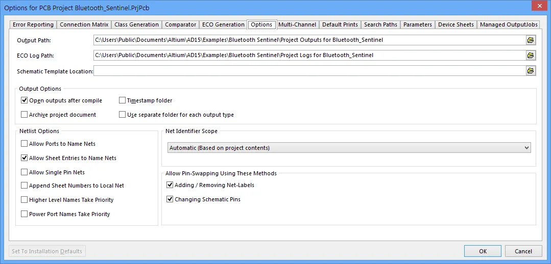
The project options are configured in the Options for Project dialog, press F1 over any of the Tabs for help.
More on project Option settings
More information on project Options dialog settings
The options and settings that can be configured in the various Options dialog tabs include the following:
Settings defined in the Options for Project dialog are stored in the project file (*.PrjPcb). Other project settings that are defined in other dialogs and then stored in the project file include:
- Schematic annotation settings.
- Output settings such as; reports, print, Gerber, and so on. Note that these are the output settings accessed via the schematic or PCB editor menus, rather than the output settings defined in an OutJob document.
The Projects panel
The Projects panel is command central when it comes to working with projects and their constituent design documents in Altium NEXUS. Open the panel with View » Panels » Projects, or click on the Panels button at the bottom right of the main application window and choose Projects.
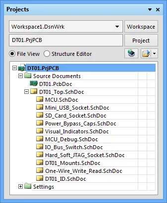
The content of the Projects panel is a logical representation of an opened project.
Most project-related tasks are available from the Projects panel, which can be used in conjunction with the Files and Storage Manager panels to fully manage design projects of all types, and from all storage sources.
► To learn more about the Projects panel including icons and display options, see Projects Panel.
Project Insight is a navigation tool available from the Projects panel, which enables you to graphically preview documents in the current project – see Project Insight.
Design Workspace
In Altium NEXUS you can open and edit multiple projects, and if desired, save the collective set projects as a Design Workspace.
This can be of particular advantage when the set of projects are related or linked, such as PCB project that includes an Embedded or FPGA project. In this case, the latter projects may include embedded software/hardware that will be loaded into a device in the PCB design project. Creating a Design Workspace that includes all the relevant projects allows you to open, manipulate and save the multiple projects as a single entity.
More on using Design Workspaces
More on using Design Workspaces
- In the Projects panel, the uppermost entry displays the current Workspace – either the default one, or one you have created or opened.
- To save the currently opened set of projects as a Design Workspace or open an existing workspace (
*.DsnWrk), click the  button at the top of the Projects panel, or use the commands in the File menu.
- When opening a different Workspace, the current workspace must be closed. You will be prompted to save any unsaved documents, projects or changes to the current Workspace first.
- To add further projects to a Design Workspace, compile all workspace projects, or save a workspace under a different name or location, select the relevant command from the
 button drop down menu.
- The current Design Workspace and its Projects, along with the constituent documents, can be graphically browsed in the Workspace view of the Altium NEXUS Home page. This can be opened from the main menu View » Workspace command, by clicking
 » Workspace in the Projects panel, or by using the Ctrl+` keyboard shortcut.

Work with a set of related projects as a Design Workspace.
Create a new project
A new Altium NEXUS project can be created in a number of ways, from different locations:
The New Project dialog
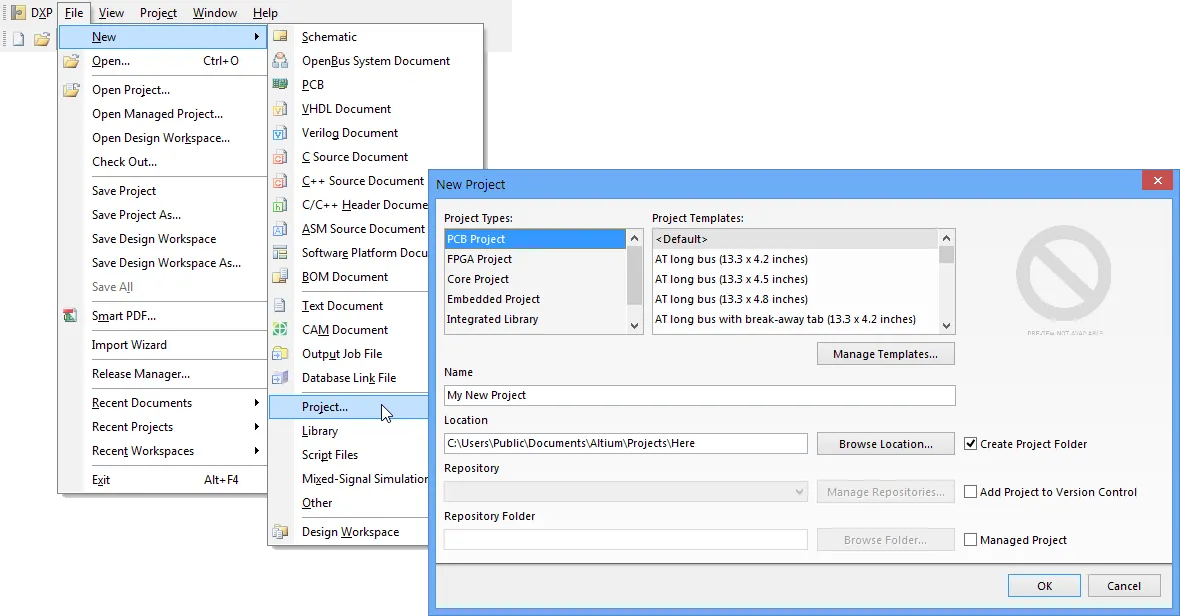
Select File » New » Project from the main menu and choose the project type, template and storage configuration in the New Project dialog.
► For details on the dialog options, see New Project.
This approach provides the most comprehensive set of options for creating a new project. These include the ability to specify a project name and container folder, whether the project will be added to a version controlled Design Repository, or if the project will reside in an Altium Vault as a Managed Project.
The Projects panel menus
If no projects are open in the Projects panel, right click within the panel (or click the  button), and then select Add New Project and its type from the context menus.
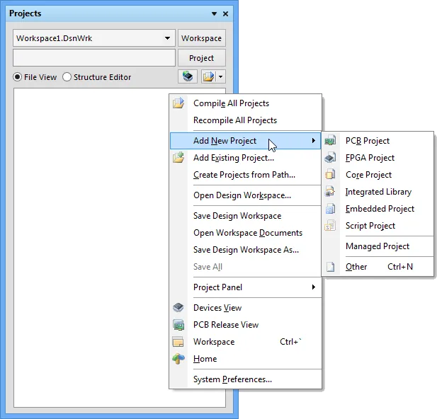
When you create a new project using any of the methods outlined here, its corresponding project entry will appear in the Projects panel. Any documents that are part of that project, and any new ones that are subsequently added, will appear under sub-folders (groups) according to their purpose and/or type.
A new project file that has not been created through the New Project dialog will only exist in memory. Use the File » Save Project or File » Save Project As commands to save the new project with a suitable name in the required location.
The Files panel
Select a suitable entry from one of the sections in the Files panel. Open the panel with View » Workspace Panels » System » Files, or click on the System button at the bottom right of the main application window and choose Files.
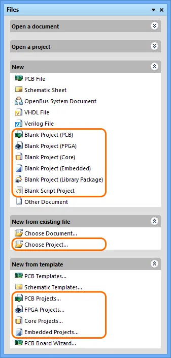
The panel section options include:
- New — Blank Project (xxx): Creates a basic project with default settings.
- New from existing file — Choose Project: Creates a renamed replica of a nominated existing project.
- New from template — xxx Projects: Opens the New Project dialog (see above) to predefine the project configuration and target storage.
Note: FPGA, Core and Embedded project filenames should not include spaces.
The Vault browser interface (Managed Project)
To directly create a new Managed Project (under Version Control) in an Enterprise Altium Vault, open the Vault Web Interface and click  (or the 'Add a Project' link) under the PROJECTS tab.
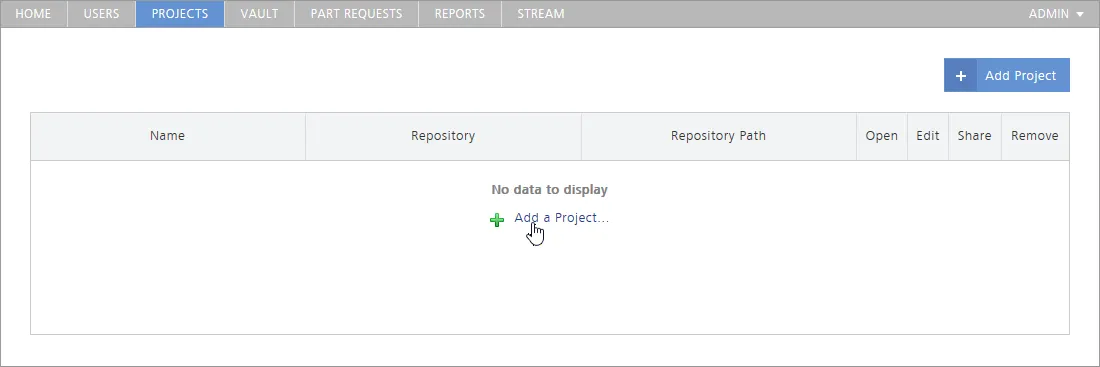
The created project document can be opened in Altium NEXUS by:
- selecting the Open Managed Project option (
 ) associated with its project entry under the PROJECTS tab in the Vault Web Interface, then clicking the
  button on its project page.
- using the File » Open Managed Project command in Altium NEXUS, then selecting the new project from the listing in the Open Managed Project dialog.
Working with project documents
Once you have created a project and saved it to the required location, design documents can be added, edited or removed from the active project.
These operations can be performed within the Projects panel, which provides a organized view of the project structure and its constituent design documents. The panel's right-click context menus offer the majority of commands required for working with design documents.
► See the Projects panel page for more information.
Note that the presentation of documents in the Projects panel does not reflect how they are stored on the hard drive or elsewhere. The panel's contents can be considered as a logical representation of the project, whereas the physical location and organization of the document file storage (and its type) is up to you – the documents might be stored in a folder on your local machine or a LAN, in a local, remote or vault-based version-controlled repository, or as fully managed project within the Altium Vault.
As you work with project documents in Altium NEXUS, the Projects panel provides a visual summary of which document files are modified, saved or hidden through status icons that are associated with each design document, and the main project file. The document icons and their status meaning are listed below:
| [blank] |
Closed – The document is not open. |
 |
Open – The document is open as a tabbed document in the design editor window. |
 |
Hidden – The document is hidden (open, but not displayed in the workspace). |
 |
Modified – The document is open and has been modified (yet to be saved). |
 |
Modified (project) – This icon appears next to the main project document to show that its structure has been modified (yet to be saved). |
A modified document or project that has yet to be saved is also distinguished by an asterisk next to its entry in the panel. Modified documents are also indicated by an asterisk inside their tab in the design editor window.
Add or remove a design document
The simplest way to add new or existing design documents to a project is to right-click on the project name in the Projects panel and select Add New to Project or Add Existing to Project from the context menu options. These options are also available from the  button.

Add a specific or other type of document to a project.
Other types of project-relevant documents can also be added to a project, such as Word® files, PDFs, spreadsheets, etc. To do so, use the Add Existing to Project option and set the File Type drop down list in the Choose Document to Add dialog to All Files (*.*) so all file types can be accessed.
To remove a document from the project structure. right click on its name in the Projects panel and select the Remove from Project menu option – or access that option by selecting the document entry and clicking the  button. Note that this process removes the project's link to that document, and does not delete the document file itself.
Change project document order
Documents in the Projects panel are automatically arranged in logical groups or 'folders', such as Source documents (Schematic, PCB etc), Settings documents (Harness, Outjob, etc) and in the case of a hierarchical design, top-level schematic documents. The documents within each folder group are displayed, by default, in the order they were added, but can be dragged and dropped to a new order position within the group.
In the case of a new hierarchical design, the parent-child relationship between documents will be displayed in the panel when the project has been Compiled. Note that the connectivity relationships cannot be defined by dragging and dropping schematic documents, since the inter-sheet connections and design hierarchy are in fact defined by Sheet Symbols and Port definitions.
► For more information about project hierarchy, see Creating Connectivity and the Net Identifier Scope section in the Options tab of the Project Options dialog.
Share documents between projects
Because an Altium NEXUS project defines and saves links to stored document files, any number of projects can be created that link to those same documents files.
While this may be a convenient way to re-use established design documents – say, including a standard power supply schematic in several projects – it is not recommended practice because a change in the document will affect all projects it is linked to. A far better approach for design reuse is to establish and apply Managed Sheets.
► For more information about design document reuse and Managed Sheets, see the Managed Sheets page in the Design Reuse area.
Save design documents with a new name
A document in a project can be saved under a new name using the File » Save As command, which creates a copy of the document file under the nominated new name. The command is available when the document is currently open.
This process automatically adds (links) the new document copy to the active project in place of the existing (source) document. It therefore serves the function of a document rename, but the original document file remains intact and is replaced within the project by the new, renamed copy. If the open document is not part of a project – a free document – the new copy is simply opened in the editor in place of the original document.
If the intention is to just make a back-up copy of a document, use the File » Save Copy As option. This creates a named copy of the document file without affecting its host project.
Save a project document with a new name
In the same process as described above, saving a project document under a new name creates a copy of the project file and updates its links accordingly – the new project copy will be linked to the same constituent design documents as the original.
This process does not create a copy of the complete project, even if the project file is saved to another location. To create a full copy of a project, use the operating system to copy the project directory to a new location, or use Altium NEXUS's Project Packager (see below).
The Storage Manager
To allow greater control over the management of document files in projects, Altium NEXUS features a dedicated Storage Manager panel. The Storage Manager presents a folder/file view of the active project's documents, and includes details of each document including its Version Control status and (when selected) its incremental history.
Open the Storage Manager panel by clicking the System button at the bottom of the application window and selecting Storage Manager menu option, or select View » Workspace Panels » System » Storage Manager from the main menu.
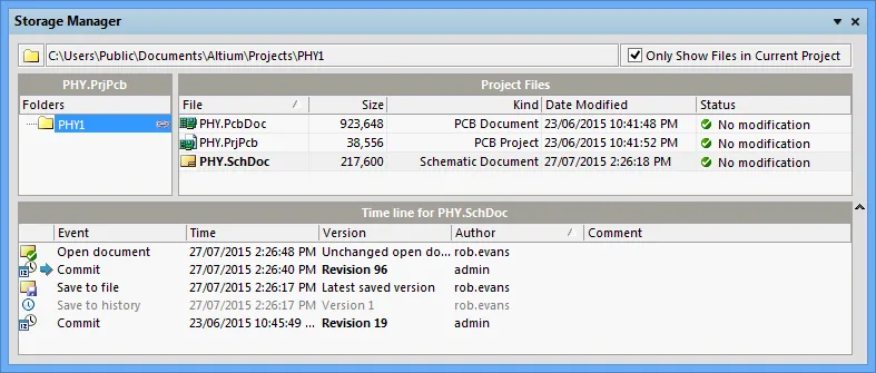
The Storage Manager provides a range of commands and options for managing project documents from a single location. Use the right click menus to perform both Version Control operations (Commit, Update etc) and standard file management actions (Open, Copy, Rename etc). The panels lower section displays the time line for a selected document, and provides right click options for advanced actions such as comparing historical file versions and reverting to a previous document version.
Some of the capabilities offered by the Storage Manager are also available in other panels, such as the Projects panel (file and version control management) and via the Local History dialog (Compare version) – Project » Local History » Show Local History. However, the Storage Manager panel brings these features and many more into a single convenient location for managing project document files.
► Read more information about the Storage Manager
The Project Packager is provided for situations where an entire project needs to be backed up or transferred to another location.
The wizard based packager archives a complete Altium NEXUS project, tree of projects or Design Workspace (and its constituent projects) to a nominated location as a single time-stamped zip file. The wizard is accessed from the main menu (Project » Project Packager) or by right clicking on a project and selecting Project Packager from the context menu.
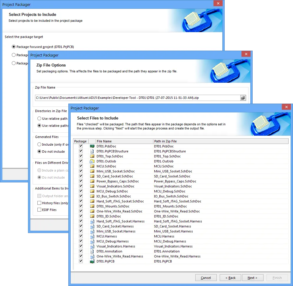
Use the Project Packager to transfer an entire project (or tree of projects) and its linked documents to an time stamped zip file.
The wizard provides options for determining:
- Where the archive is to be stored.
- How file directory paths are handled.
- Whether any generated, system or external files are included.
- If the project history is included.
- Which of a project's linked documents are included in the final archive.
See Also
► Project Navigation
► Auto save and Local History
► Version Control and Design Repositories
► Design Variants
