회로도 심볼은 일반적으로 부품의 기능을 반영할 수 있는 도형과 하나 이상의 핀을 포함합니다. 부품을 어떻게 표현할지, 즉 심볼의 모양과 부품 핀의 배치는 설계자가 결정합니다. 이는 조직의 요구사항과 채택한 설계 표준을 준수하도록 수행되어야 합니다. 하나의 부품 심볼이 물리적 부품 전체를 나타낼 수도 있고, 부품을 여러 개의 하위 파트로 정의하여 각 하위 파트가 물리적 부품 내부의 어떤 논리적 엔티티를 나타내도록 할 수도 있습니다(예: 쿼드 AND 게이트 부품에서 각 AND 게이트, 또는 릴레이의 코일과 접점 세트). 이러한 유형의 부품은 멀티 파트 부품(multi-part component)이라고도 합니다.
새 회로도 심볼 만들기
회로도 심볼은 연결된 Workspace에서 직접 생성할 수 있습니다:
-
메인 메뉴에서 File » New » Library 를 선택한 다음, 열리는 New Library 대화상자에서 대화상자의 Workspace 영역에 있는 Create Library Content » Symbol 를 선택합니다.
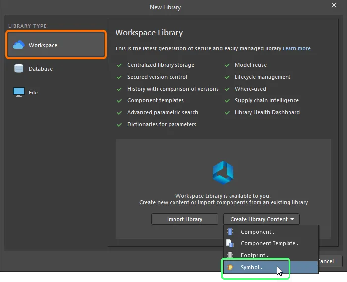
New Library 대화상자를 사용하여 새 Workspace Symbol 만들기
-
열리는 Create New Item 대화상자에서 필요한 정보를 입력하고, Open for editing after creation 옵션이 활성화되어 있는지 확인한 뒤 OK을(를) 클릭합니다. Workspace Symbol이 생성되고, 임시 회로도 심볼 편집기가 열리면서 .SchLib 문서가 활성 문서로 표시됩니다. 이 문서는 Item-Revision에 따라 다음 형식으로 이름이 지정됩니다: <Item><Revision>.SchLib (예: SYM-001-0001-1.SchLib). 이 문서를 사용하여 심볼을 아래에 설명된 대로 정의합니다.
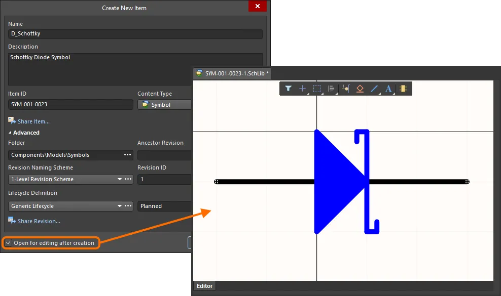
Workspace Symbol의 초기 리비전을 편집하는 예 – 임시 회로도 심볼 편집기는 회로도 심볼을 정의하는 데 사용할 문서를 제공합니다.
-
심볼을 요구사항에 맞게 정의한 후, Projects 패널에서 심볼 항목(entry) 오른쪽에 있는 Save to Server 컨트롤을 사용하여 Workspace에 저장합니다. 그러면 Edit Revision 대화상자가 나타나며, 여기서 Name, Description을 변경하고 필요에 따라 릴리스 노트를 추가할 수 있습니다. 저장 후 문서와 편집기는 닫힙니다.
저장된 Workspace Symbol은 Single Component Editing mode 또는 Batch Component Editing mode에서 Component Editor로 부품을 정의할 때 사용할 수 있습니다.
Workspace Symbols는 Components 패널에서 찾아볼 수 있습니다. 패널 상단의  버튼을 클릭하고 Models을(를) 선택하여 모델 표시를 활성화한 다음, Symbols 카테고리를 선택합니다.
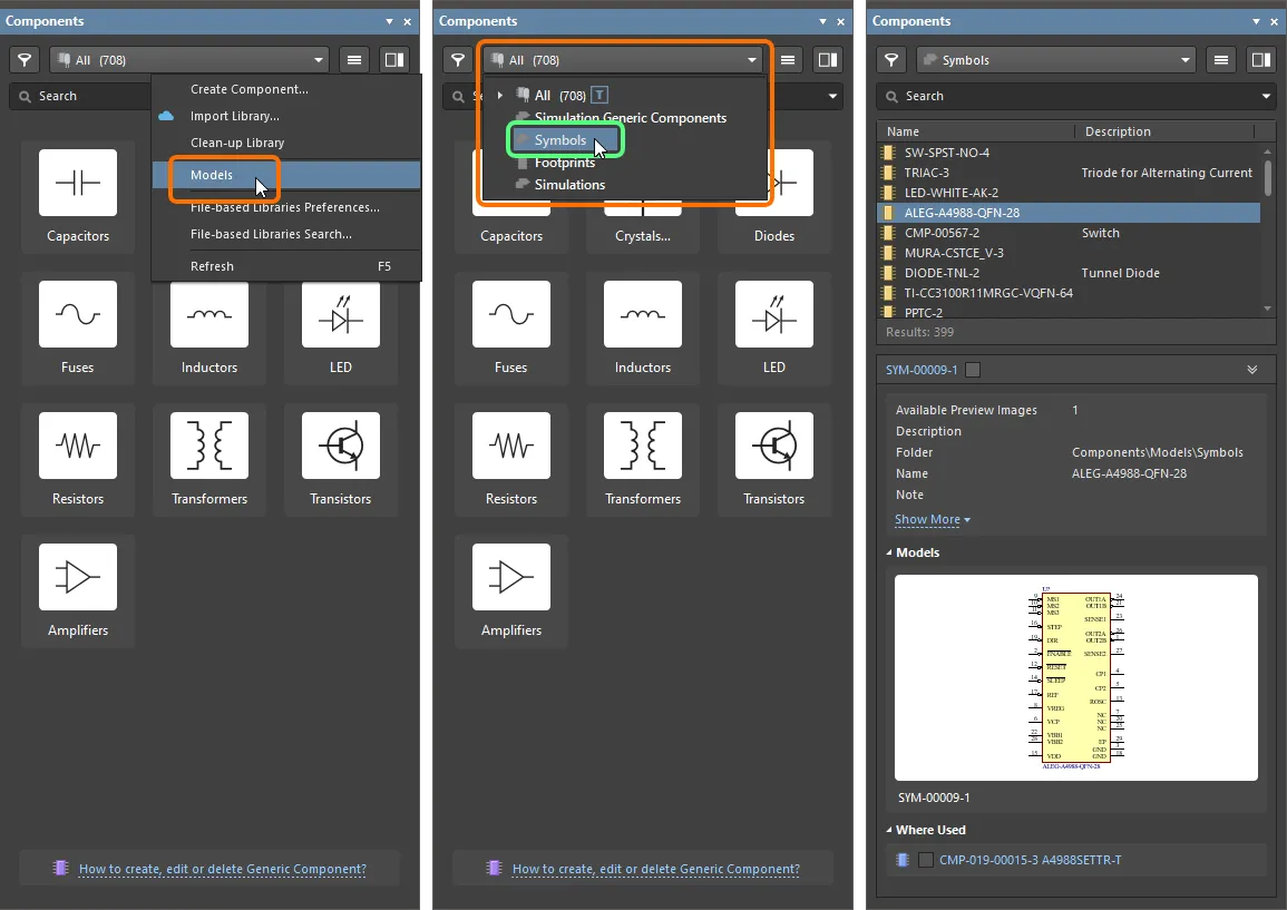
Workspace Symbol을 편집하려면 Components 패널에서 해당 항목을 마우스 오른쪽 버튼으로 클릭하고 Edit 명령을 선택합니다. 그러면 다시 임시 편집기가 열리고, 심볼이 편집을 위해 열립니다. 필요한 변경을 수행한 뒤 문서를 저장하여 Workspace Symbol의 다음 리비전에 반영합니다.
편집한 심볼을 Workspace에 저장할 때 심볼의 현재 라이프사이클 상태를 유지할 수 있습니다. 이 기능은 다시 저장할 때( ) Create Revision 대화상자에서 사용할 수 있는 Preserve lifecycle state (not recommended) 옵션을 통해 제어됩니다. 이 옵션을 활성화하면 새 심볼 리비전이 이전 리비전의 라이프사이클 상태로 자동 설정됩니다. 이 기능은 Allow to skip lifecycle state change for new revisions 운영 권한이 할당된 사용자에게 제공됩니다(Workspace에 대한 전역 작업 권한 설정에 대해 자세히 알아보기).
Updating Related Component
Workspace 도메인 모델(심볼, 풋프린트 모델, 시뮬레이션 모델 등)을 변경한 뒤 그 변경을 모델의 새 리비전에 저장하는 순간, 해당 모델을 사용하는 모든 Workspace Components는 이전 리비전을 계속 사용하게 되어 사실상 최신 상태가 아니게 됩니다. 대부분의 경우, 사용 가능한 최신 리비전을 사용하도록 해당 모델 링크를 업데이트한 상태로 Workspace Components를 다시 저장하고 싶을 것입니다. 이 과정을 간소화하기 위해 Workspace는 Altium Designer와 함께, 직접 편집 기능을 통해 모델을 수정한 후 Workspace 모델을 다시 저장하는 시점에 관련 컴포넌트를 업데이트할 수 있는 기능을 제공합니다.
상위(부모) 컴포넌트에 대해 이 업데이트를 수행하는 옵션은 수정된 Workspace Symbol을 대상 Workspace에 다시 저장할 때 나타나는 Create Revision 대화상자에서 찾을 수 있습니다. 이 옵션(Update items related to <ModelItemRevision>)은 기본적으로 활성화되어 있습니다.
<ModelItemRevision>는 모델의 현재 리비전, 즉 관련 Workspace Components가 현재 사용 중인 리비전을 의미합니다. Workspace 모델 자체가 저장되면, 이는 자연스럽게 이전(더 이른) 리비전이 되며 더 이상 최신이 아닙니다.
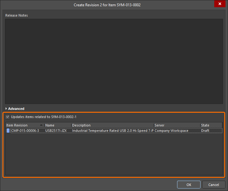
다시 저장되는 Workspace Symbol을 참조하는 관련 Workspace Components를 업데이트하는 옵션에 접근하는 방법.
관련된 모든 컴포넌트가 Workspace Symbol의 현재 리비전을 계속 사용하도록 유지하려면 이 옵션을 비활성화하십시오. 그러면 Workspace 모델 자체만 저장됩니다.
Create Revision 대화상자에서 OK을(를) 클릭하면 수정된 심볼이 Workspace에 다시 저장되고, 연결된 임시 편집기는 닫힙니다. 해당 Workspace Symbol을 참조하는 모든 Workspace Components는 새 리비전을 사용하도록 자동으로 다시 저장됩니다(각 컴포넌트의 다음 리비전이 자동으로 생성되고 저장이 수행됨).
-
설계자 관점에서 Workspace Component는 모든 설계 도메인 전반에서 해당 부품을 표현하는 데 필요한 모든 정보를 하나의 엔티티로 모아 둡니다. 따라서 이런 의미에서 컨테이너, 즉 모든 도메인 모델과 파라메트릭 정보가 저장되는 ‘버킷(bucket)’으로 생각할 수 있습니다. 여러 도메인에서의 표현 측면에서 Workspace Component는 Workspace 도메인 모델 자체를 포함하는 것이 아니라, 이러한 모델에 대한 링크를 포함합니다. 이 링크는 부품을 정의할 때 지정됩니다.
-
회로도 심볼은 기존의 구세대(SchLib, PcbLib, IntLib, DbLib, SVNDbLib) 부품 라이브러리를 가져오는 과정의 일부로 Workspace에서 생성할 수도 있습니다. 이 프로세스의 인터페이스인 Library Importer 는 처음에 선택한 라이브러리를 받아 Workspace로 가져오는 직관적인 흐름을 제공합니다. Library Importer에 대해 자세히 알아보십시오.
-
새 Workspace Symbol은 Component Editor in its Single Component Editing mode에서 Workspace Component를 정의할 때도 생성할 수 있습니다.
-
심볼은 file-based schematic symbol library의 일부로도 생성할 수 있습니다.
회로도 심볼 정의하기
회로도 심볼은 부품 본체를 나타내는 도형 객체와 실제 부품의 물리적 핀을 나타내는 핀을 배치하여 생성합니다. 회로도 심볼은 Altium Designer의 회로도 심볼 편집기에서 생성됩니다.
심볼 생성 관련 참고 사항:
-
라이브러리 편집기에 배치된 객체는 배치된 순서대로 쌓입니다. 핀이 부품 본체 뒤에 가려지는 경우 Edit » Move 명령을 사용하여 표시 순서를 변경하십시오.
-
핀의 한쪽 끝만 전기적입니다. 이 끝을 핫스팟(hotspot)이라고 합니다. 핫스팟(핀을 잡는 쪽 끝)이 부품 본체에서 떨어져 있도록 하십시오. 자세한 내용은 Pin object를 참조하십시오.
-
회로도 라이브러리 편집기에서는 기본 설계자(designator)와 설명(description) 같은 현재 활성 심볼의 속성을 Symbol 모드의 Properties 패널에서 편집합니다. 아무것도 선택되지 않았을 때 패널은 이 모드로 표시됩니다. 부품 심볼의 일부로 배치된 프리미티브를 더블 클릭하면 Properties 패널은 상위 부품이 아니라 해당 프리미티브의 속성을 표시합니다.
-
심볼 편집기 시트에서 설계자와 코멘트를 표시하는 데 사용되는 옵션(Show Comment/Designator)은 Properties 패널의 Library Options 모드에서 현재 라이브러리에 대해 활성화/비활성화됩니다. Tools » Document Options 명령을 선택하여 Properties 패널을 이 모드로 표시하십시오.
-
폰트는 객체를 배치할 때 각 객체별로 개별 설정할 수 있으며, 또는 Preferences 대화상자의 Schematic - Defaults page 에서 해당 객체들을 편집하여 새 객체에 대한 선호 폰트를 설정할 수도 있습니다.
-
Schematic Symbol Generation Tool을 사용하면 핀 수가 많은 부품을 빠르게 구성할 수 있습니다. 또한 이 도구는 마우스 오른쪽 버튼 메뉴를 통해 스프레드시트에서 핀 세부 정보를 가져오는 기능도 지원합니다.
-
여러 핀을 스프레드시트에서 현재 심볼로 가져오려면 SCHLIB List 패널의 오른쪽 클릭 메뉴에 있는 Smart Grid 명령을 사용하십시오 – 자세히 알아보기.
Workspace Symbol을 만들 때는 심볼 그래픽만 정의하면 된다는 점에 유의하십시오. 즉, 회로도 편집 도메인에서 상위 수준 부품을 표현하는 방식만 정의하면 됩니다. 이는 구형 파일 기반 부품 관리 방법론에서 사용되던 ‘schematic component’처럼, 다른 모델과 파라미터가 그 회로도 부품의 일부로 정의되는 개념이 아닙니다. 부품에는 심볼의 그래픽 표현만 필요합니다. 다른 도메인 모델과 파라미터에 대한 링크는 부품 자체의 정의에 포함됩니다.
컴포넌트 심볼을 만들기 시작하기 전에, 선호하는 기본값을 구성하는 데 시간을 조금 투자하는 것이 좋습니다. 모든 회로도 설계 객체(라이브러리와 시트 모두)의 기본값은 Schematic - Defaults 페이지에서 Preferences 대화상자에 의해 설정됩니다. Preferences dialog page가 열려 있을 때, 옵션에 대한 자세한 정보는 F1를 눌러 확인할 수 있습니다.
디자인 공간 준비
컴포넌트 심볼은 항상 시트 원점(시트 중앙) 가까이에 그리십시오. 필요하다면 Edit » Jump » Origin를 선택(단축키 J, O)하여 시트 원점을 디자인 창의 중앙으로 옮길 수 있습니다. 화면 왼쪽 하단의 Status bar를 확인하여 커서가 원점에 있는지 확인하십시오. Altium에서 제공하는 컴포넌트는 이 지점을 기준으로 생성되며, 시트 중앙을 가로지르는 십자선으로 표시됩니다. 컴포넌트는 항상 이 원점 근처에서 생성해야 합니다.
회로도에 컴포넌트를 배치할 때, 컴포넌트는 라이브러리 심볼의 시트 원점에 의해 ‘잡힌(held)’ 상태로 배치됩니다. 심볼을 만들 때 흔히 사용하는 방법은 컴포넌트의 1번 핀 핫스팟을 시트 원점에 두는 것으로, 이렇게 하면 라이브러리에서 회로도 시트로 배치할 때 해당 핀에 의해 잡힌 상태가 됩니다. 이것은 필수는 아니며(시트 어디에든 심볼 핀과 바디 객체를 배치할 수 있습니다), 심볼 객체를 원점에서 떨어진 곳에 배치하면 라이브러리에서 회로도 시트로 배치할 때 컴포넌트가 커서로부터 동일한 거리만큼 떨어진 상태로 나타납니다.
회로도 및 회로도 라이브러리 그리드의 기본 단위는 인치(Imperial)입니다. 모든 Altium 컴포넌트는 이 인치 그리드에서 설계되므로, 시트 그리드를 미터법으로 전환하기로 결정할 때의 영향을 이해하는 것이 중요합니다. 서로 다른 그리드에서 생성된 컴포넌트에 정확히 배선하기가 어려워지기 때문입니다. A3 같은 미터법 시트 크기에서도 인치 그리드를 사용할 수 있으므로, 미터법 크기의 시트로 작업한다고 해서 반드시 미터법 그리드로 바꿀 필요는 없습니다. 현재 시트의 단위는 Library Options 모드의 Properties panel에 있는 Properties panel의 General region 내 General 탭에서 정의됩니다(메인 메뉴의 Tools » Document Options 명령을 사용하여 Properties panel의 이 모드에 접근).
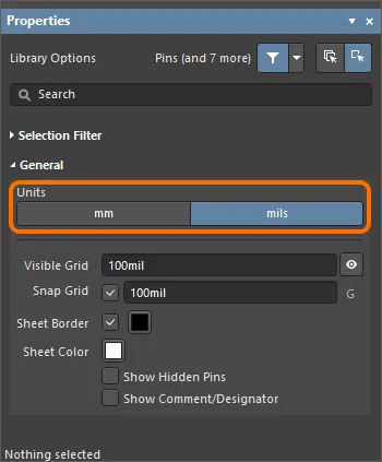
Library Options mode 의 Properties panel에 있는 General region 을 사용하여 현재 시트의 단위를 설정하십시오.
원한다면 Properties panel 에서 Show Comment/Designator 옵션을 활성화하여, 라이브러리 문서에서 현재 컴포넌트의 Comment/Designator 문자열을 표시할 수 있습니다.
객체는 현재 스냅 그리드에 배치됩니다. 현재 그리드는 디자인 공간 하단의 Status bar 왼쪽 끝에 표시됩니다.

Library Options mode. 의 Properties panel에서도 Snap Grid 및 Visible Grid 를 설정할 수 있습니다. 그리드를 변경할 때마다 Properties panel을 여는 대신, G 를 눌러 스냅 그리드를 사용 가능한 설정들 사이에서 순환(cycle)할 수 있습니다. 사용 가능한 설정은 Schematic – Grids 페이지에서 Preferences 대화상자에 의해 편집할 수 있습니다.
일반적으로 객체와 핀은 100 mil 또는 50 mil 그리드에 배치하며, 10 mil 그리드에 배치해야 하는 객체는 문자열(strings)뿐입니다. 텍스트 문자열의 위치를 잡는 동안 도움이 되도록, 문자열을 이동할 때 Ctrl를 눌러 그리드를 일시적으로 가장 미세한 설정(기본값 10 mil)으로 전환할 수 있습니다.
Properties Panel
활성 문서가 Schematic Library 문서(*.SchLib)인 경우, 메인 메뉴에서 Tools » Document Options 명령을 선택하십시오. 그러면 Properties panel이 Library Options를 표시합니다. 다음의 접을 수 있는 섹션에는 사용 가능한 옵션과 컨트롤에 대한 정보가 포함되어 있습니다.
Selection Filter
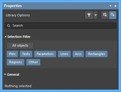
이 섹션의 옵션은 디자인 공간에서 어떤 회로도 라이브러리 객체를 선택할 수 있는지를 결정합니다.
-
All Objects button – 객체 필터링 제거를 선택하여 모든 유형의 객체를 선택할 수 있도록 합니다.
-
Object buttons – 각 객체 버튼을 토글하여 해당 객체 유형을 선택할 수 있는 기능을 활성화/비활성화합니다.
General
설계 객체를 선택하면, 패널은 해당 객체 유형에 특화된 옵션을 표시합니다. 다음 표는 라이브러리 디자인 공간에 배치할 수 있는 객체 유형을 나열합니다. 링크를 클릭하면 해당 객체의 속성 페이지로 이동합니다.
회로도 심볼 바디 생성
필요에 따라 디자인 공간 옵션을 설정한 다음 단계는 컴포넌트의 그래픽 표현을 캡처하는 것, 즉 회로도 시트에 배치될 때 해당 컴포넌트를 나타낼 심볼 그래픽을 만드는 것입니다. 준수할 그래픽 회로도 심볼 표준을 결정하는 것이 중요합니다. 이는 심볼 그래픽을 설계할 때 공식 템플릿을 제공하고, 일관성이 보장된 결과를 만들어 줍니다. Altium의 설계 방법론은 표준 IEEE 315를 따르며, 이는 가장 일반적인 회로 요소를 다룰 뿐 아니라 반도체 요소를 조합하여 다양한 실리콘 디바이스 유형을 심볼로 표현하는 방법도 명확히 정의합니다.
심볼의 바디는 Place menu, Utilities bar 또는 Active Bar를 사용하여 회로도 라이브러리 편집기 디자인 공간에 그래픽 설계 객체를 배치함으로써 생성됩니다. 배치된 회로도 심볼을 더블클릭하여 Properties panel을 열고 각 도형을 추가로 정의하십시오.
Altium Designer에는 아래에 표시된 것처럼 rectangle, polygon, ellipse, round rectangle 등 다양한 닫힌(closed) 심볼 도형이 포함되어 있습니다.

선(line) 유형 도형에는 arc, line/polyline, bezier, elliptical arc가 포함됩니다. line/polyline에는 화살촉(arrowheads)과 꼬리(tails)를 포함할 수 있습니다. 더블클릭하여 Properties panel을 열고 head와 tail을 정의하십시오.

심볼에 핀 추가
컴포넌트 핀은 컴포넌트에 전기적 특성을 부여하고, 신호를 입출력하기 위한 컴포넌트의 연결 지점을 정의합니다. 실제 물리적 컴포넌트의 각 핀을 나타내기 위해 핀을 하나씩 배치합니다.
다음 방법 중 하나를 사용하여, schematic library 문서 디자인 공간에 현재 표시된 컴포넌트에 핀을 추가할 수 있습니다. 각 경우에서 핀은 전기적 끝(electrical end)에 의해 잡힌 상태로 커서에 떠서 나타납니다. 필요에 따라 핀을 회전 및/또는 뒤집은 다음 클릭하여 배치하십시오.
-
Place » Pin 명령(또는 단축키 P, P)을 사용합니다.
-
Active Bar에서  버튼을 클릭합니다.
-
Utilities toolbar의 design object 드롭다운에서  버튼을 클릭합니다.
-
Component Pin Editor dialog 사용 – 디자인 공간에서 어떤 객체도 선택되어 있지 않을 때, Properties panel을 사용하여 핀 편집/추가/삭제를 포함한 심볼 속성을 편집할 수 있습니다. 또한 패널에서 Component Pin Editor dialog로 접근할 수 있습니다. 열려면 Properties panel의 Pins 탭에서  버튼을 클릭하십시오. 이 대화상자는 심볼에 연결된 어떤 핀의 특정 속성도 수정할 수 있는 단일하고 편리한 위치를 제공합니다. 핀 속성을 편집하는 수단을 제공하는 것 외에도, 새 핀을 추가하거나 기존 핀을 삭제할 수도 있습니다.
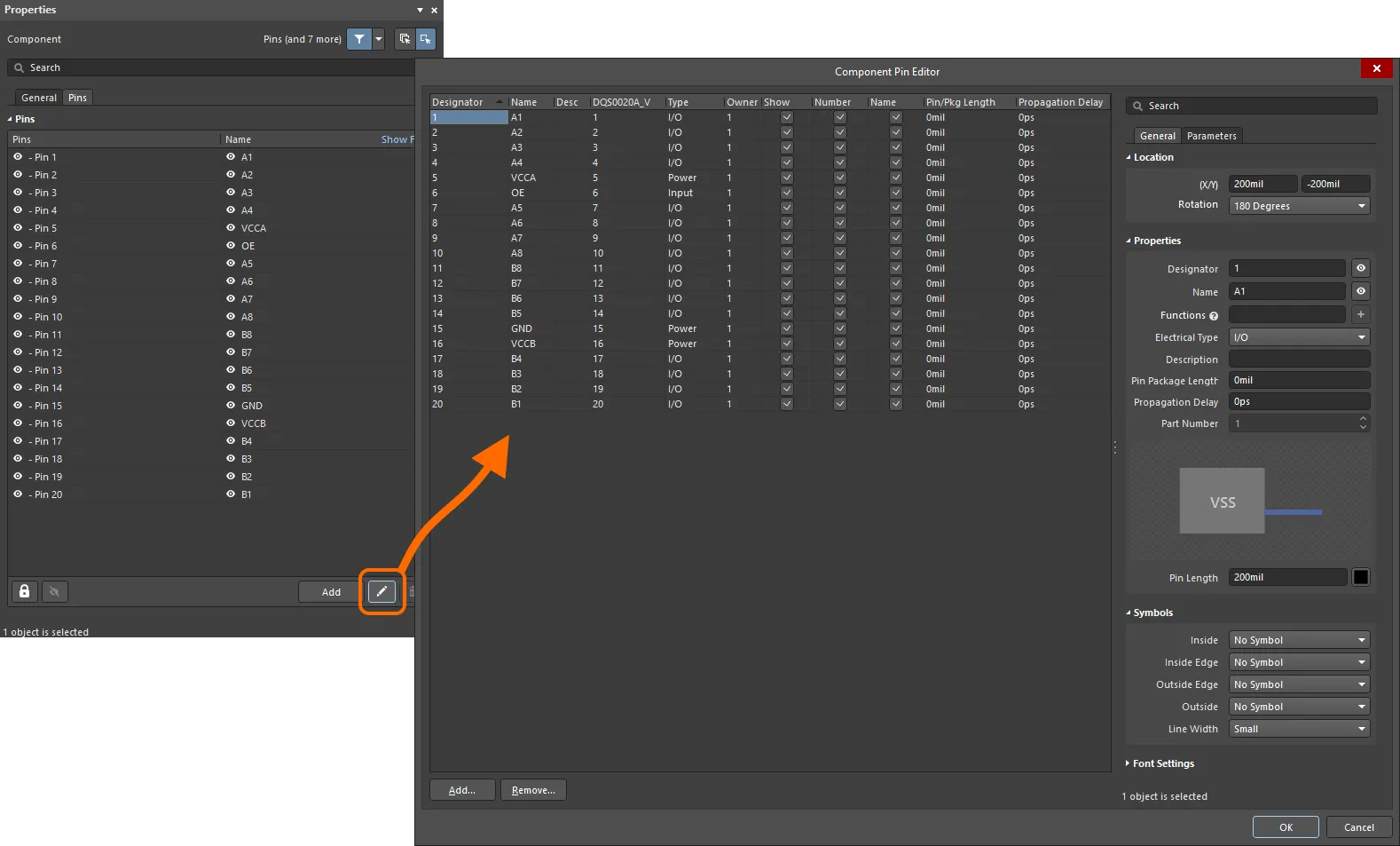 생성한 심볼의 모든 핀을 관리하기 위해 Component Pin Editor dialog에 접근하십시오.
Options and Controls of the Component Pin Editor Dialog
Pin Grid
이 영역에는 컴포넌트의 모든 핀이 표시됩니다. 각 핀에 대해 다음 정보가 표시됩니다.
-
Designator – 핀의 숫자 식별자입니다. 파트의 각 핀은 고유한 designator를 가져야 합니다.
-
Name – 핀의 표시 이름입니다. 이름은 선택 사항이며, 필요하다면 이 필드는 비워 둘 수 있습니다. 또는 Name 텍스트 필드에 문자열을 입력한 다음, Name 체크박스를 사용하여 이름을 표시하거나 숨길 수 있습니다.
-
Desc – 핀의 설명입니다.
-
Footprint Model Mapping – 이 회로도 컴포넌트의 해당 핀이 매핑되는, 연결된 풋프린트 모델의 지정 pad입니다. 연결된 각 풋프린트 모델마다 별도의 열이 표시됩니다.
-
Type – 핀의 전기적 유형입니다. 이 유형은 프로젝트를 컴파일하거나 회로도 문서를 분석할 때( Electrical Rules Check 기능 사용) 전기적 연결 오류를 감지하는 데 사용됩니다. 사용 가능한 유형은 Input, I/O, Output, Open Collector, Passive, HiZ, Open Emitter, Power입니다.
-
Owner – 핀이 연관되는 상위 파트입니다. 단일 파트 컴포넌트의 경우 이 항목은 항상 1이며, 멀티 파트 컴포넌트에서만 의미가 있습니다. 멀티 파트 컴포넌트에는 비그래픽 파트인 Part Zero도 포함됩니다. Part Zero는 멀티 파트 컴포넌트의 모든 파트에 포함되어야 하는 핀(예: 전원 핀)에 사용됩니다.
-
멀티 파트 컴포넌트의 경우 전원 넷 연결은 이상적으로 Part Zero를 사용해 할당하는 것이 좋습니다. 핀을 배치한 다음 Part Number 속성을
0로 설정하면 해당 핀이 Part Zero에 포함됩니다. Part Zero에 배치된 핀은 모든 파트에 표시됩니다.
-
필요한 경우 Part Zero에 배치된 핀을 숨길 수도 있습니다 . 이 방식은 권장되지 않지만, 이런 방식으로 전원 넷에 연결해야 하는 각 핀에 대해 SCHLIB List 패널 또는 SCH List 패널의 Hidden Net Name 필드에 넷 이름을 입력한 다음 Component Pin Editor dialog에서 Show 옵션을 비활성화(또는 SCHLIB List 패널이나 SCH List 패널에서 Hide 옵션을 활성화)합니다.
-
Show – 핀이 시트에 표시되는지(활성화) 또는 숨겨지는지(비활성화)를 반영합니다. 이 방식은 권장되지 않지만, 멀티 파트 컴포넌트의 전원 핀은 회로도 시트에서 표시할 경우 불필요하게 복잡해질 때 숨길 수 있습니다.
컴포넌트의 숨겨진 핀은 회로도 편집기 또는 회로도 라이브러리 편집기에서 Properties 패널의 Pins 영역에 있는 Show All Pins 옵션을 활성화하여 시트에 표시되도록 할 수 있습니다. 회로도 라이브러리 편집기에서는 Edit 메인 메뉴에서 Show Hidden Pins 옵션도 활성화해야 합니다.
-
Number – 상위 파트를 회로도 시트에 배치할 때 핀의 설계자(designator)를 표시(활성화)할지 숨김(비활성화)할지 결정하는 데 사용됩니다.
-
Name – 상위 파트를 회로도 시트에 배치할 때 핀의 표시 이름(display name)을 표시(활성화)할지 숨김(비활성화)할지 결정하는 데 사용됩니다.
핀 이름을 부정(이름 위에 바를 표시)하려면 다음 방법 중 하나를 사용합니다:
-
핀 이름의 각 문자 뒤에 백슬래시 문자를 추가합니다(예:
H\O\L\D\).
-
Preferences dialog의 Schematic – Graphical Editing page에서 Single '\' Negation 옵션을 활성화한 다음, 핀 이름의 시작 부분에 백슬래시 문자 하나를 추가합니다(예:
\HOLD).
-
Pin/Pkg Length – 핀-패키지 길이입니다.
-
Propagation Delay – 전파 지연(propagation delay)을 표시합니다. 이는 신호의 선두가 송신자에서 수신자로 이동하는 데 걸리는 시간입니다.
-
Add – 이 버튼을 클릭하여 컴포넌트에 새 핀을 추가합니다. 새 핀에는 다음으로 사용 가능한 설계자(핀 0일 수도 있음)가 할당되며, 다음 기본 속성을 갖습니다:
-
Name –
1
-
Desc – 공백
-
Mapping – 모두
0
-
Type –
Passive
-
Owner – 활성/선택된 파트의 번호.
-
Show/Number/Name – 모두 활성화됨.
dialog에서 OK를 클릭하면, 새로 추가된 핀은 처음에 컴포넌트(또는 해당 파트)의 오른쪽 아래에 배치됩니다. 필요에 따라 위치를 조정하십시오.
-
Remove – 이 버튼을 클릭하여 현재 선택된 핀을 컴포넌트에서 제거합니다. 확인 dialog가 열리며, 제거를 진행하려면 Yes를 클릭합니다. 회로도에 배치된 컴포넌트 인스턴스에서 핀을 제거하는 경우, 해당 핀에 연결되어 있던 기존 배선을 다시 연결해야 할 수 있습니다.
다음 팁은 Pin Grid 작업과 관련이 있습니다:
-
상위 파트에 연결된 모델의 매핑 정보를 표시하는 필드를 제외하고, 모든 필드는 편집할 수 있습니다. 필드를 한 번 클릭해 선택한 다음 값을 입력하거나 필요한 옵션을 선택합니다. 필드 밖을 클릭하거나 Enter를 눌러 변경 사항을 적용합니다.
-
멀티 파트 컴포넌트의 경우 활성/선택된 파트의 핀은 일반적인 흰색 배경으로 표시되고, 다른 모든 파트의 핀은 회색 배경으로 표시됩니다.
-
핀은 각 경우의 열 헤더를 사용하여 다양한 필드 기준으로 정렬할 수 있습니다. 한 번 클릭하면 오름차순으로 정렬되고, 다시 클릭하면 내림차순으로 정렬됩니다. Shift+Click를 사용해 추가 필드로 정렬합니다. Ctrl+Click를 사용해 정렬을 제거합니다.
Right-Click Menu
그리드의 우클릭 메뉴는 다음 명령을 제공합니다:
-
Jump – 설계 공간에서 현재 선택된 핀으로 이동(가능한 경우 확대 및 중앙 정렬)하는 데 사용합니다.
-
Add – 컴포넌트(또는 해당 파트)에 새 핀을 추가하는 데 사용합니다.
-
Remove – 현재 선택된 핀을 컴포넌트에서 제거하는 데 사용합니다. 확인 dialog가 열리며, 제거를 진행하려면 Yes를 클릭합니다.
-
Edit – 이 명령은 동작하지 않습니다.
-
Report – Report Preview dialog를 여는 데 사용합니다.
Properties Region
General Tab
Parameters 탭
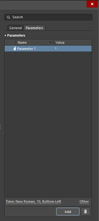
-
Parameters – 이 영역에는 현재 핀에 대해 정의된 모든 파라미터가 나열됩니다.
 또는
또는  아이콘을 사용하여 설계 공간에서 해당 파라미터 값의 표시/숨김을 전환합니다.
  또는
또는  아이콘을 사용하여 해당 파라미터를 잠금/잠금 해제합니다.
-
Name – 파라미터의 이름입니다. 규칙(rule) 타입 파라미터의 경우 이 항목은
Rule로 잠깁니다.
-
Value – 파라미터의 값입니다. 규칙 타입 파라미터의 경우, 항목에는 규칙 타입과 함께 정의된 제약 조건 목록이 반영됩니다.
-
Font – 클릭하여 메뉴를 열고 원하는 글꼴, 글꼴 크기, 색상 및 굵게/기울임 등 속성을(필요 시) 선택합니다.
-
Other – 클릭하여 드롭다운을 열고 추가 옵션을 변경합니다:
-
Show Parameter Name – 파라미터 이름을 표시하도록 활성화합니다.
-
Allow Synchronization with Database – 데이터베이스와 동기화하도록 활성화합니다.
-
X/Y – X 및 Y 좌표를 입력합니다.
-
Rotation – 드롭다운을 사용하여 회전(rotation)을 선택합니다.
-
Autoposition – 자동 위치 지정(auto-positioning)을 활성화하려면 체크합니다.
-
Add – 클릭하여 파라미터를 추가합니다.
 을 사용하여 현재 선택된 파라미터를 삭제합니다.
멀티파트 컴포넌트의 경우, 선택된 파트에 해당하는 핀은
Component Pin Editor 대화상자에서 강조 표시됩니다. 다른 파트의 모든 핀은 회색으로 표시됩니다.
Component Pin Editor 대화상자는 회로도 편집기에서도 배치된 컴포넌트(또는 그 일부)에 대해 접근할 수 있습니다.
핀 속성 구성
Tab을 눌러 Properties 패널의 Component 모드를 열고 배치 전에 핀 속성을 편집합니다. 숫자 값은 이후 핀을 연속 배치할 때 자동으로 증가합니다. 자동 증가 동작은 Preferences 대화상자의 Schematic – General 페이지에 있는 Auto-Increment During Placement 설정에서 구성합니다. 음수 값을 사용하면 자동 감소합니다.
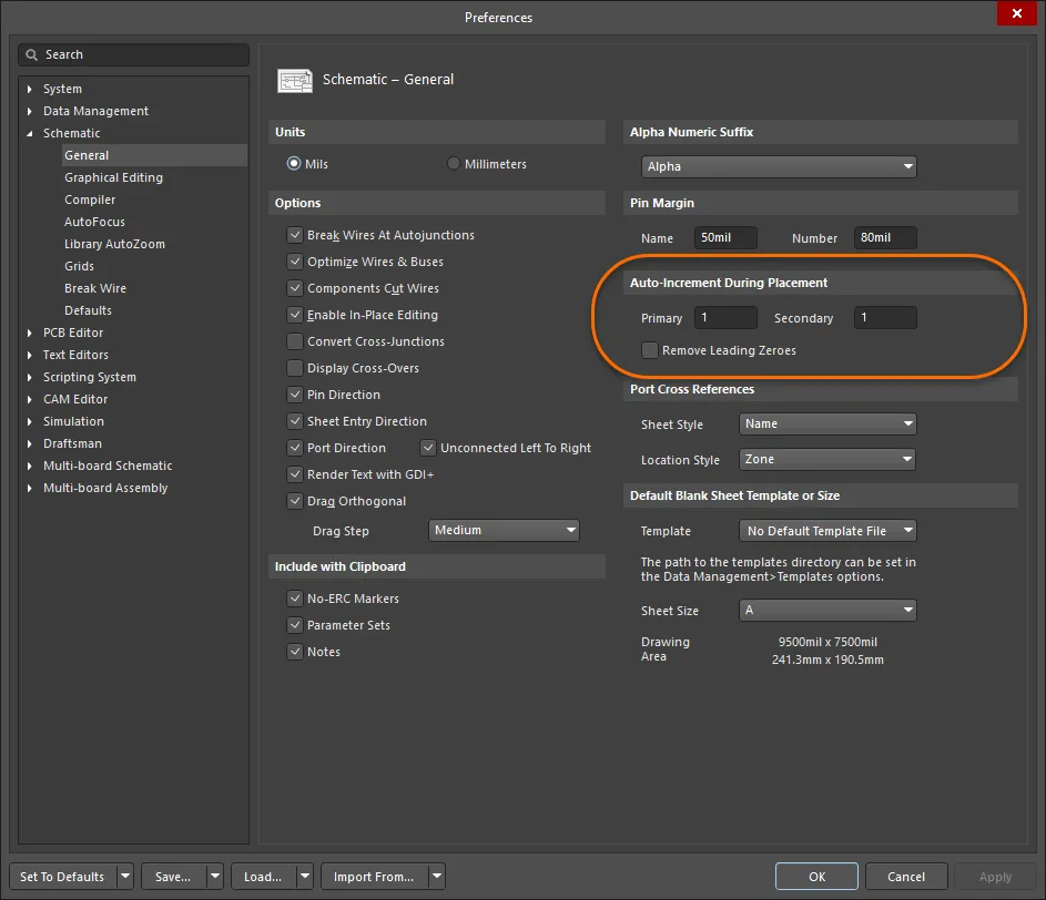
Preferences 대화상자의 Schematic - General 페이지를 사용하여 자동 증가 동작을 정의합니다. 배치 중이거나 핀이 이동될 때마다 핀은 전기적 끝단(핀의 핫 엔드라고도 함)을 기준으로 잡힙니다. 전기적 끝단이 컴포넌트 바디에서 바깥쪽을 향하도록 핀을 배치해야 합니다. 이동 중 스페이스바를 누르면 핀이 회전합니다.
핀은 전압 레귤레이터의 탭(tab)과 같은 컴포넌트의 전기-기계적 지점을 나타내기 위해서도 배치할 수 있습니다.
핀에는 Name과 Designator를 포함한 여러 속성이 있습니다. 심볼 핀을 PCB 풋프린트 패드와 매칭하는 데 사용되는 것은 핀 Designator입니다. 핀 끝에서 핀의 Designator 및 Name 가 표시되는 기본 거리는 회로도 및 회로도 라이브러리 편집기 전체에 적용되는 시스템 전역 설정입니다. Preferences 대화상자의 Schematic – General 페이지에서 Pin Margin를 구성합니다.
Name 에 대한 개별 설정은 Component Pin Editor 대화상자에서 구성할 수 있습니다.
핀에는 Altium의 전기 규칙 검사 시스템이 핀-대-핀 연결의 유효성을 검증하는 데 사용하는 Electrical Type가 있습니다. 해당 컴포넌트 핀의 전기적 타입에 맞게 Component Pin Editor 대화상자에서 이 옵션을 설정합니다. 기본 Pin Length은 선택한 스냅 그리드(일반적으로 100 mil 또는 50 mil)에 적합해야 합니다. 기본 길이는 30이며, 일반적인 길이는 20 또는 30입니다.
Symbols Component Pin Editor 대화상자에서 핀의 서로 다른 위치에 추가하여 핀의 전기적 정보를 나타낼 수 있습니다.
Pin
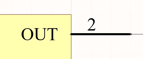
회로도 핀은 회로도 설계 공간에서 물리적 컴포넌트 핀을 나타냅니다.
요약
핀은 전기 설계 프리미티브입니다. 핀은 컴포넌트(파트)에 전기적 속성을 부여하고, 입력 및 출력 신호를 위한 파트의 연결 지점을 정의합니다.
사용 가능 여부
핀은 다음 방법 중 하나를 사용하여 회로도 라이브러리 편집기에서만 배치할 수 있습니다:
-
메인 메뉴에서 Place » Pin를 클릭합니다.
-
Utilities 툴바(
 )의 드롭다운에서
  를 클릭합니다.
-
마우스 오른쪽 버튼을 클릭한 다음 컨텍스트 메뉴에서 Place » Pin를 선택합니다.
배치
명령을 실행하면 커서가 십자선으로 바뀌고 핀 배치 모드로 들어갑니다. 배치는 다음 순서의 동작을 수행하여 이루어집니다:
- 핀을 고정하려면 클릭하거나 Enter 를 누르십시오. 떠 있는 핀은 전기적 끝단(전기 엔드)으로 잡히며, 이 끝단은 반드시 부품 본체에서 바깥쪽으로 향하도록 배치해야 합니다. 핀의 한쪽 끝만 전기적 끝단이며, 핀은 항상 이 끝단을 기준으로 잡힙니다.
-
추가 핀을 계속 배치하거나, 마우스 오른쪽 버튼을 클릭하거나 Esc 를 눌러 배치 모드를 종료하십시오.
배치 중(핀을 커서에 떠 있는 상태로 두고, 핀의 전기적 끝단을 고정하기 전)에 수행할 수 있는 추가 동작은 다음과 같습니다:
-
Tab 키를 눌러 배치를 일시 정지하고, Properties 패널의 Pin mode에 접근하여 속성을 즉시 변경할 수 있습니다. 배치를 재개하려면 디자인 공간의 일시정지 버튼 오버레이(
 )를 클릭하십시오.
-
Alt 키를 눌러 이동 방향을(초기 이동 방향에 따라) 수평 또는 수직 축으로 제한합니다.
-
Spacebar 를 눌러 핀을 반시계 방향으로 회전하거나, Shift+Spacebar 를 눌러 시계 방향으로 회전합니다. 회전은 90° 단위로 이루어집니다.
-
X 또는 Y 키를 눌러 핀을 X축 또는 Y축을 기준으로 미러링합니다.
라이브러리 편집기 시트의 원점(중앙) 근처에 라이브러리 컴포넌트를 생성하십시오. 원점은 짙은 십자선으로 표시됩니다. 일반적으로 핀 하나 또는 부품 본체의 모서리를 시트 원점에 배치합니다.
핀 번호(Designator)는 연결성을 설정하는 데 사용되므로 반드시 정의해야 합니다. Electrical Type 또한 중요한데, 이는 회로도 편집기에서 Electrical Rules Check(ERC)에 사용되기 때문입니다.
핀 번호 지정에 대한 참고
많은 부품에는 숫자 이름과 번호를 가진 핀들이 연속으로 존재합니다. 이러한 핀의 배치를 빠르게 하기 위해 Preferences 대화상자의 Schematic – General page 에 있는 Auto-Increment During Placement 기능을 사용할 수 있습니다. 배치 전에 핀 속성을 편집하면(핀이 커서에 떠 있는 동안 Tab 누름) 자동 증가가 자동으로 호출됩니다. 이 기능은 Designator 및 Name 모두에 대해 동작하며, 핀 Designator는 Primary 자동 증가 필드를 사용하고 핀 Name는 Secondary 자동 증가 필드를 사용합니다. 알파/숫자 오름차순 값과 숫자 내림차순 값을 지원합니다.
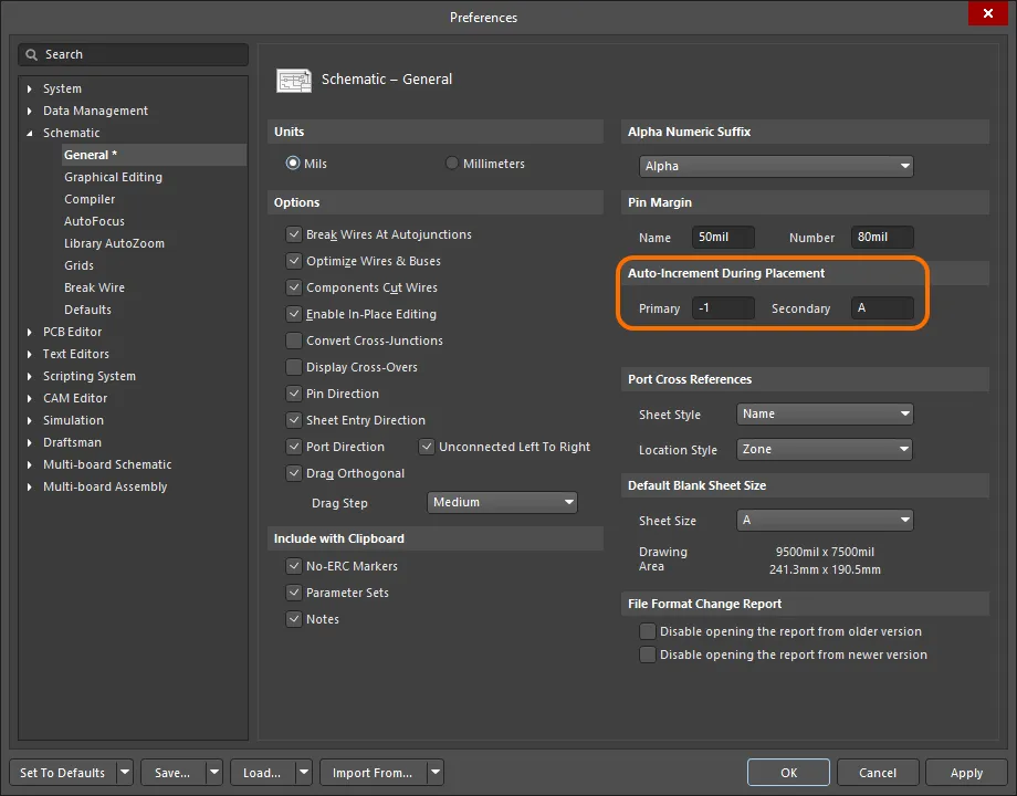
Preferences 대화상자의 Schematic – General 페이지에서 Auto-Increment During Placement 설정을 구성하십시오.
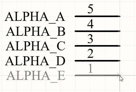
알파 핀 이름은 증가하고 숫자 핀 번호는 감소하는 점에 유의하십시오.
그래픽 편집
핀을 이동하려면 클릭한 채로 유지하십시오. 커서가 핀의 전기적 핫스팟 끝단으로 이동합니다. 이를 새 위치로 옮긴 뒤, 전기적 끝단이 부품 본체에서 바깥쪽을 향하도록 배치하십시오.
드래그하는 동안 핀은 회전(Spacebar/Shift+Spacebar) 또는 미러링(X 또는 Y 키로 X축 또는 Y축 기준 미러링)할 수 있습니다.
비그래픽 편집
핀 대화상자 또는 속성 패널을 통한 편집
Properties page: Pin Properties
핀의 속성은 Pin 대화상자와 Properties 패널에서 편집할 수 있으며, 이 패널을 통해 디자인 공간에서 현재 선택된 모든 항목을 편집할 수 있습니다.
핀 표시 이름 및 디자인레이터 – 위치와 글꼴
핀 표시 이름과 핀 디자인레이터(번호)의 위치는 Preferences 대화상자의 Schematic – General page 에 있는 Pin Margin 설정으로 전역적으로 정의됩니다. 이는 환경 설정이므로, 설정이 정의된 PC에 적용됩니다. 이 설정은 핀의 비전기적 끝단으로부터 텍스트가 떨어진 상대 거리를 정의합니다.
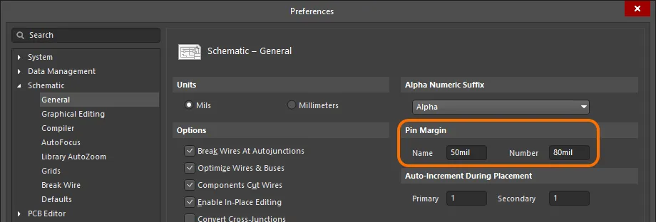
Preferences 대화상자에서 핀 텍스트 거리(Pin Margin)를 설정하십시오.
회로도 라이브러리 문서의 기본 시스템 글꼴은 Times New Roman, 10pt, Regular입니다. 이는 고정되어 있으며 변경할 수 없습니다. 라이브러리 컴포넌트를 회로도 시트에 배치하면 동일한 기본 글꼴이 적용되지만 고정은 아니며 필요에 따라 변경할 수 있습니다. 회로도 시트에 사용되는 시스템 글꼴은 Power Ports, Ports, 그리고 회로도 시트 테두리의 X, Y 영역 마커를 포함한 다른 객체에도 적용된다는 점을 유의하십시오.
핀의 경우, 이러한 시스템 수준의 위치 및 글꼴 설정을 재정의할 수 있습니다. 핀의 Designator 및 Name에 대한 위치/글꼴 사용자 정의 제어는 Properties 패널의 Pin 모드에서 찾을 수 있습니다.
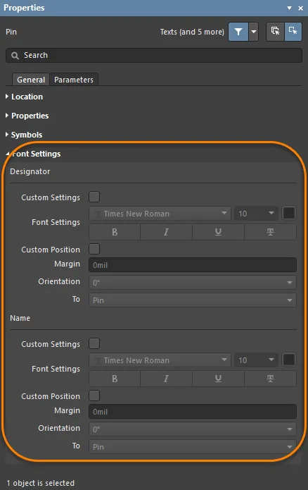
필요한 경우 개별 핀에 대해 핀 Designator(번호) 및 Name의 글꼴과 위치를 수정할 수 있습니다.
Custom Position 옵션을 사용하여 위치에 대한 기본 설정을 재정의하는 사용자 지정 위치로 변경하십시오. Margin의 경우, 관련 필드에 새 값을 직접 입력하십시오. Orientation의 경우, 드롭다운을 사용하여 각도(0° 또는 90°)와 To 기준(Pin 또는 Component)을 선택하십시오.
Custom Settings 옵션을 사용하여 기본 시스템 글꼴 사용에서 재정의된 사용자 지정 글꼴 사용으로 변경하십시오.
핀 심볼 선 두께
회로도 편집 영역에서 부품을 표현할 때, 해당 디바이스의 회로도 심볼에 정의된 각 핀은 하나 이상의 심볼을 표시할 수 있습니다. 필요에 따라 주 부품 심볼 외곽선에 대해 Inside, Inside Edge, Outside, Outside Edge 위치에 표시되는 심볼들입니다. 예를 들어 Inside Edge의 Clock 심볼 또는 Outside Edge의 Dot 심볼이 있을 수 있습니다. 이러한 심볼은 특정 핀을 통과하는 신호의 목적을 시각적으로 표시함으로써 설계의 가독성을 크게 향상시킵니다.
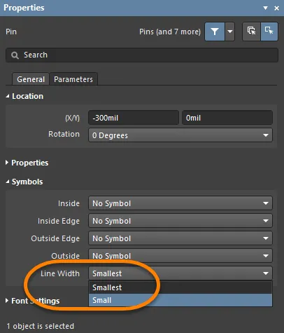
Properties 패널의 Symbols 영역에 있는 Line Width 설정을 사용하여 이러한 심볼을 그리는 데 사용되는 선의 두께를 지정하십시오. Small 또는 Smallest 중에서 선택하십시오.
오래된 설계에는 때때로 숨겨진 전원 핀을 가진 부품이 포함되어 있었고, 이 핀들은 해당 전원 넷에 연결되었습니다. 이 방식은 권장되지 않지만, 숨겨진 핀은 SCHLIB List 또는 SCH List 패널의 Hidden Net Name 필드에 넷 이름을 입력하여 연결할 수 있습니다.
Pin Properties

General 탭
위치
-
(X/Y)
-
X (첫 번째 필드) – 현재 디자인 공간 원점을 기준으로 한 객체 기준점의 현재 X(수평) 좌표입니다. 편집하여 객체의 X 위치를 변경합니다. 값은 미터법 또는 인치법으로 입력할 수 있으며, 현재 기본 단위가 아닌 단위로 값을 입력할 때는 단위를 함께 포함하십시오.
-
Y (두 번째 필드) – 현재 원점을 기준으로 한 객체 기준점의 현재 Y(수직) 좌표입니다. 편집하여 객체의 Y 위치를 변경합니다. 값은 미터법 또는 인치법으로 입력할 수 있으며, 현재 기본 단위가 아닌 단위로 값을 입력할 때는 단위를 함께 포함하십시오.
-
Rotation – 드롭다운을 사용하여 회전을 선택합니다.
속성
Symbols
이 기호들은 순수하게 그래픽 요소입니다. 핀의 실제 전기적 속성은 핀의 Electrical Type에 대해 설정된 항목에 의해 결정됩니다.
-
Inside – 컴포넌트 그래픽의 내부에 핀 기호를 선택적으로 추가하는 데 사용합니다.
-
Inside Edge – 컴포넌트 그래픽의 내부 가장자리에 핀 기호를 선택적으로 추가하는 데 사용합니다.
-
Outside Edge – 컴포넌트 그래픽의 외부 가장자리에 핀 기호를 선택적으로 추가하는 데 사용합니다.
-
Outside – 컴포넌트 그래픽의 외부에 핀 기호를 선택적으로 추가하는 데 사용합니다.
-
Line Width – 기호를 그리는 데 사용되는 선의 두께를 결정하는 데 이 필드를 사용합니다. 이는 해당 기호가 컴포넌트 심볼을 그리는 선과 동일한 두께여야 한다고 규정하는 GOST 표준을 충족하는 데 도움이 됩니다.
The Line Width setting will also apply to the automatic symbol used in relation to the pin's defined Electrical Type.
Font Settings
-
Designator
-
Custom Settings – 아래의 Font Settings에 접근하여 글꼴을 사용자 지정할 수 있도록 활성화합니다.
-
Font Settings – 컨트롤을 사용하여 글꼴, 글꼴 크기, 색상 및 굵게/밑줄과 같은 특수 설정을 구성합니다.
-
Custom Position – 아래 컨트롤에 접근하여 위치를 사용자 지정할 수 있도록 활성화합니다.
-
Margin – 원하는 여백을 입력합니다.
-
Orientation – 드롭다운을 사용하여 방향을 선택합니다.
-
To – 드롭다운을 사용하여 디자인레이터의 원하는 객체를 선택합니다.
-
Name
-
Custom Settings – 아래의 Font Settings에 접근하여 글꼴을 사용자 지정할 수 있도록 활성화합니다.
-
Font Settings – 컨트롤을 사용하여 글꼴, 글꼴 크기, 색상 및 굵게/밑줄과 같은 특수 설정을 구성합니다.
-
Custom Position – 아래 컨트롤에 접근하여 위치를 사용자 지정할 수 있도록 활성화합니다.
-
Margin – 원하는 여백을 입력합니다.
-
Orientation – 드롭다운을 사용하여 방향을 선택합니다.
-
To – 드롭다운을 사용하여 이름의 원하는 객체를 선택합니다.
Parameters Tab
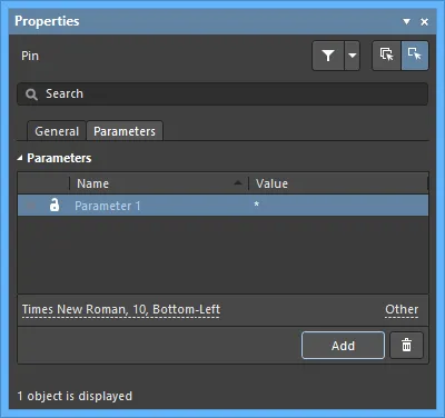
Parameters
이 영역을 사용하여 현재 선택된 핀 객체에 연결된 파라미터를 관리합니다.
-
Grid – 이 영역에는 현재 핀에 대해 정의된 모든 파라미터가 나열됩니다.
 또는
또는  아이콘을 사용하여 설계 공간에서 해당 파라미터 값의 표시/숨김을 전환합니다.
  또는
또는  아이콘을 사용하여 해당 파라미터를 잠금/잠금 해제합니다.
-
Name – 파라미터의 이름입니다. 규칙(rule) 유형 파라미터의 경우 이 항목은
Rule로 잠깁니다.
-
Value – 파라미터의 값입니다. 규칙 유형 파라미터의 경우 항목에는 규칙 유형과 함께 정의된 제약 조건 목록이 반영됩니다.
-
Font – 클릭하여 원하는 경우 글꼴, 글꼴 크기, 색상 및 굵게/기울임 등 속성을 선택하는 메뉴를 엽니다.
-
Other – 클릭하여 추가 옵션을 변경하는 드롭다운을 엽니다.
-
Show Parameter Name – Schematic Library 편집기에서 파라미터 이름을 표시하도록 활성화합니다.
-
Allow Synchronization with Database – 데이터베이스와 동기화하도록 활성화합니다. 이 옵션은 코멘트를 업데이트할 수 있는지 제어하는 데 사용됩니다. 기본적으로 이 옵션들은 소스 라이브러리/데이터베이스와의 동기화를 항상 허용하도록 활성화되어 있습니다. 업데이트 과정에 해당 코멘트가 포함되지 않도록 하려면 이 옵션을 비활성화할 수 있습니다.
-
X/Y – 원하는 X 및 Y 좌표를 입력합니다.
-
Rotation – 드롭다운을 사용하여 회전을 선택합니다.
-
Autoposition – 자동 위치 지정을 활성화하려면 체크합니다. 즉, 컴포넌트를 이동 및 회전해도 텍스트가 선택한 위치에 유지됩니다.
-
Add – 클릭하여 파라미터를 추가합니다.
 를 사용하여 현재 선택된 파라미터를 삭제합니다.
이전 설계에는 적절한 전원 넷에 연결된 숨겨진 전원 핀을 가진 컴포넌트가 포함되기도 했습니다. 이 방법은 권장되지 않지만, 숨겨진 핀은 SCHLIB List 또는 SCH List 패널의 Hidden Net Name 필드에 넷 이름을 입력하여 연결할 수 있습니다.
Pasting Array
표준 잘라내기, 복사, 붙여넣기 명령 외에도, 컴포넌트 심볼을 생성할 때 메인 메뉴의 Edit » Paste Array 명령을 사용하여 현재 클립보드 내용을 현재 문서에 수직 또는 수평 객체 배열로 배치할 수 있습니다. 이는 생성 중인 컴포넌트 심볼에 여러 핀이 포함되어야 할 때 특히 유용합니다.
명령을 실행하면 Setup Paste Array 대화상자가 나타납니다.
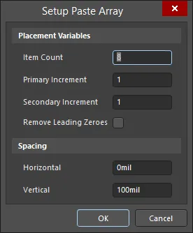
The Setup Paste Array dialog
Options and Controls of the Setup Paste Array Dialog
Placement Variables
-
Item Count - 이 필드를 사용하여 작업 공간에 붙여넣을 중복 항목의 총 개수를 지정합니다.
-
Primary Increment - 이 필드를 사용하여 증가(증분) 값을 지정합니다. 숫자 값을 증가시키려면 증가 단계(step)를 정수 값으로 입력하면 됩니다. 알파벳으로 증가시키려면 건너뛸 글자 수를 나타내는 알파벳 문자를 입력합니다. 예를 들어 초기 텍스트가 1A인 경우, 1씩 증가시키려면 이 필드를 A(알파벳의 첫 글자)로 설정합니다. 이 필드를 C(알파벳의 세 번째 글자)로 설정하면 텍스트는 1A, 1D(A에서 세 글자 뒤), 1G 등으로 바뀝니다. 붙여넣는 객체가 핀인 경우 이 필드는 Pin Designator에 영향을 줍니다.
-
Secondary Increment - 이 필드는 핀 객체 배열을 붙여넣을 때만 적용되며 Pin Display Name에 영향을 줍니다. Primary Increment 필드에 따라 증가량을 지정하는 데 사용합니다.
숫자 값의 경우 증분은 증가 또는 감소가 될 수 있습니다. Primary Increment 및/또는 Secondary Increment 필드에 증가의 경우 양의 정수, 감소의 경우 음의 정수를 입력합니다.
-
Remove Leading Zeroes - 이 옵션을 활성화하면 붙여넣은 배열 텍스트에서 선행 0을 제거합니다. 표준 텍스트 문자열의 경우 이는 문자열의 숫자 부분에 대한 선행 0에만 해당하며, 알파 문자 앞에 붙는 0은 제거하지 않습니다. 예를 들어 텍스트 문자열 C000020은 (Primary Increment 1 사용 시) C21로 붙여넣어지고, 텍스트 문자열 000C000020은 000C21로 붙여넣어집니다. 핀 객체를 붙여넣을 때는 이는 Pin Designator에만 해당하며 Pin Display Name에는 해당하지 않습니다.
Spacing
-
Horizontal - 이 필드에 값을 입력하여 각 배열 항목의 수평 변위를 결정합니다. 양수 값은 배열을 커서 위치의 오른쪽에 배치합니다. 음수 값은 배열을 왼쪽에 배치합니다.
-
Vertical - 이 필드에 값을 입력하여 각 배열 항목의 수직 변위를 결정합니다. 양수 값은 배열을 커서 위치에서 위쪽으로 배치합니다. 음수 값은 배열을 아래쪽으로 배치합니다.
필요에 따라 다양한 옵션을 설정한 다음 OK를 클릭합니다.
간격(spacing)에 양수 또는 음수 값을 입력하여, 수평 배치에서는 배열이 각각 오른쪽/왼쪽에 붙여넣어질지, 수직 배치에서는 각각 위쪽/아래쪽에 붙여넣어질지를 결정합니다.
문서에서 배열이 삽입될 시작 위치를 선택하라는 메시지가 표시됩니다. 커서를 원하는 위치에 놓고 클릭하거나 Enter를 누르기만 하면 됩니다. 배열은 선택한 시작 위치에 붙여넣어집니다.
Adding IEEE Symbols
로직 함수 또는 디바이스를 표현하기 위해, 회로도 심볼에서 IEEE 기호를 사용할 수 있습니다. 이러한 기호를 사용하면 사용자가 내부 특성에 대한 구체적인 지식이 없어도 해당 함수/디바이스의 로직 특성을 이해할 수 있습니다.
배치 가능한 IEEE Symbols는 아래 이미지에 표시되어 있습니다.
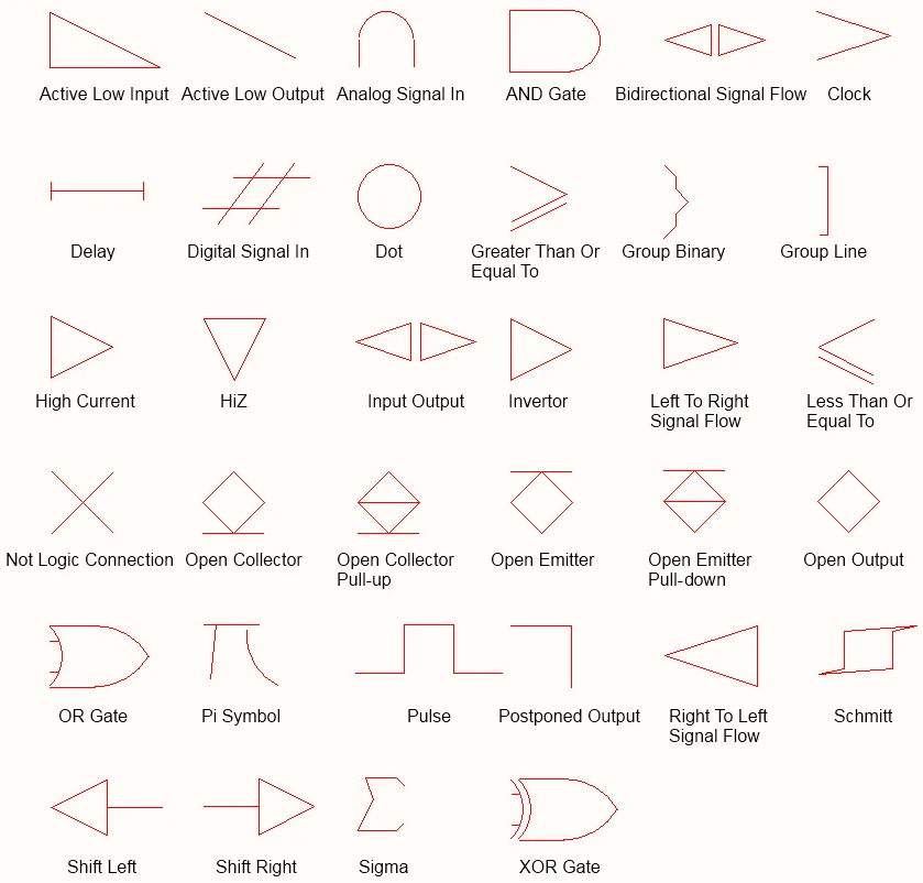
IEEE Symbols
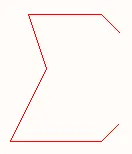
배치된 IEEE Symbol (Sigma)
Summary
IEEE 기호는 비전기적 드로잉 프리미티브입니다. 로직 함수 또는 디바이스를 표현하는 데 사용됩니다. 이러한 기호를 사용하면 사용자가 내부 특성에 대한 구체적인 지식이 없어도 해당 함수/디바이스의 로직 특성을 이해할 수 있습니다.
Availability
IEEE Symbol 객체는 Schematic Library Editor에서만 배치할 수 있습니다. 총 34개의 기호를 다음과 같은 방법으로 배치할 수 있습니다.
-
메인 메뉴에서 Place » IEEE Symbols 를 선택합니다.
-
마우스 오른쪽 버튼을 클릭한 다음 컨텍스트 메뉴에서 Place » IEEE Symbols 를 선택합니다.
-
Utilities 툴바에서
 버튼을 클릭합니다.
-
Active Bar에서 Place IEEE Symbol를 선택합니다(그러면
Open Collector 기호가 배치됩니다).
Placement
명령을 실행하면 커서가 십자선으로 바뀌고 IEEE 심볼 배치 모드로 들어갑니다. 선택한 IEEE 심볼이 커서에 떠 있는 상태로 표시됩니다.
-
개체를 원하는 위치에 놓은 다음 클릭하거나 Enter를 눌러 배치를 완료합니다.
-
추가 심볼을 계속 배치하거나, 마우스 오른쪽 버튼을 클릭하거나 Esc를 눌러 배치 모드를 종료합니다.
배치 중 수행할 수 있는 추가 동작은 다음과 같습니다:
-
Tab 키를 눌러 배치를 일시 정지하고, Properties 패널의 IEEE Symbol 모드에 접근하여 속성을 즉시 변경할 수 있습니다. 배치를 재개하려면 디자인 공간 일시정지 버튼 오버레이(
 )를 클릭합니다.
-
Spacebar를 눌러 개체를 반시계 방향으로 회전하거나, 시계 방향 회전은 Shift+Spacebar를 누릅니다. 회전은 90° 단위로 이루어집니다.
-
X 또는 Y 키를 눌러 심볼을 X축 또는 Y축을 기준으로 미러링합니다.
-
숫자 키패드의 + 또는 - 키를 눌러 심볼을 확대하거나 축소합니다.
그래픽 편집
이 편집 방법을 사용하면 디자인 공간에 배치된 IEEE 심볼 개체를 직접 선택해 위치나 방향을 그래픽으로 변경할 수 있습니다. IEEE 심볼은 형상이 고정되어 있으며, 관련 키보드 단축키를 통해서만 크기 변경이 가능합니다. 따라서 IEEE 심볼 개체를 선택해도 편집 핸들은 제공되지 않습니다.
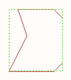
선택된 IEEE 심볼(Sigma)
점선 박스 내부를 아무 곳이나 클릭한 뒤 드래그하여 필요에 따라 심볼을 재배치합니다. 드래그하는 동안 심볼은 회전(Spacebar/Shift+Spacebar), 미러링(X축 또는 Y축 기준 미러링은 X 또는 Y 키), 크기 변경(숫자 키패드의 +/- 키)이 가능합니다.
IEEE Symbols Properties
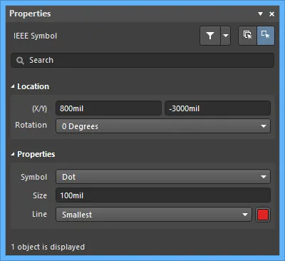
위치
-
(X/Y) - 현재 디자인 공간 원점을 기준으로 한 개체 기준점의 현재 X(수평) 및 Y(수직) 좌표입니다. 값을 편집하여 개체의 X, Y 위치를 변경합니다. 값은 미터법 또는 인치법 중 어느 것으로도 입력할 수 있으며, 현재 기본 단위가 아닌 단위로 값을 입력할 때는 단위를 함께 포함하십시오.
-
Rotation - 드롭다운을 사용해 회전을 선택합니다.
속성
-
Symbol - 그래픽 IEEE 심볼을 정의합니다. 드롭다운 목록에서 심볼을 선택합니다.
-
Size - IEEE 심볼의 현재 크기입니다. 기본 크기는 10 DXP Default Units (100mil)입니다. 이 값을 늘리거나 줄여 심볼을 더 크게 또는 더 작게 만듭니다. 음수 값을 입력하면 심볼이 180° 회전한 것처럼 표시됩니다.
-
Line - 심볼 외곽선을 그리는 데 사용되는 선의 두께입니다.
심볼 속성 정의
심볼의 설계자(Designator)와 설명(Description) 같은 심볼 속성은 Properties 패널의 Symbol 모드에서 편집합니다.
-
Designator - 필요한 설계자 접두어를 입력한 다음 ?를 붙입니다. 접두어는 문자만으로 구성하는 것을 권장합니다.
-
Name 및 Description - 이 문자열은 심볼 검색을 수행할 때 유용합니다.
-
Type 이 심볼이 나타내는 컴포넌트 유형을 정의합니다. 회사 로고(Graphical)나 방열판(Mechanical) 같은 비표준 컴포넌트도 회로도 심볼로 생성하여 프로젝트에 배치할 수 있습니다.
컴포넌트 유형
설계 환경에서는 완성된 PCB에 실장되는 컴포넌트가 아닐 수도 있는 설계 엔티티를 만들어야 하는 경우도 있습니다. 예를 들어, 보드에 연결되는 외부 모듈이 있어 이를 컴포넌트로 그려 회로도에 포함해 설계 가독성을 높이고 싶지만, 이 보드의 BOM에는 포함하고 싶지 않을 수 있습니다. 또는 방열판과 체결 나사 같은 기구 하드웨어는 BOM에는 포함되어야 하지만 회로도에는 포함하고 싶지 않을 수도 있습니다.
이러한 상황은 컴포넌트의 Type를 설정하여 관리합니다. 방금 설명한 예에서는 컴포넌트 유형을 Graphical로 설정할 수 있습니다. 또 다른 특수 컴포넌트 분류로 테스트 포인트가 있습니다. 이 컴포넌트는 회로도와 PCB 모두에 필요합니다. 설계 동기화 중에는 확인되어야 하지만 BOM에는 필요하지 않습니다. 이 경우 컴포넌트 Type 는 Standard (No BOM)로 설정됩니다.
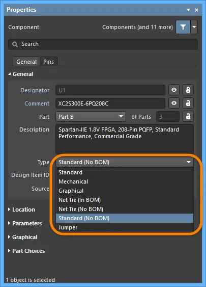
비표준 유형의 컴포넌트는 Type 를 그에 맞게 설정하십시오.
Type 필드는 컴포넌트를 BOM에 포함할지 여부를 결정하는 데 사용될 뿐 아니라, 컴포넌트 동기화 중 해당 컴포넌트를 어떻게 관리할지도 결정하는 데 사용됩니다. Standard, Net Tie, Jumper 유형은 모두 완전 동기화되며, 즉 컴포넌트가 회로도에서 PCB로 전달되고 넷 연결성이 검사됩니다. Mechanical 및 Graphical Type의 경우 컴포넌트는 회로도에서 PCB로 전달되지 않습니다. 이러한 유형 중 하나를 가진 컴포넌트를 PCB에 수동으로 배치했고 일치하는 Type 옵션을 선택했다면, 컴포넌트 수준 동기화는 수행되지만 넷 수준 연결성 검사는 수행되지 않습니다.
다양한 Type 옵션에 대한 자세한 내용은 Properties 패널의 Component mode를 참조하십시오.
컴포넌트를 여러 파트로 분할
경우에 따라 컴포넌트를 여러 개의 심볼로 나누는 것이 더 적절할 수 있으며, 각 심볼은 Part라고 합니다. 예로는 8개의 개별 저항을 포함하고 각 저항을 서로 독립적으로 사용할 수 있는 저항 네트워크, 릴레이의 코일과 접점 세트, 또는 커넥터의 각 핀 등이 있습니다. 예를 들어, 단일 커넥터 심볼로 배선을 모으는 대신 시트 전체에 커넥터 핀을 분산 배치하는 것을 선호할 수도 있습니다. 또 다른 예로 74F08SJX 4회로(quadruple) 2입력 AND 게이트가 있습니다. 이 디바이스에는 서로 독립적인 2입력 AND 게이트가 4개 있습니다. 컴포넌트를 4개의 게이트를 모두 보여주는 단일 심볼로 그릴 수도 있지만, 각 게이트를 서로 독립적으로 회로도 어디에나 배치할 수 있도록 4개의 개별 게이트로 그리는 편이 더 유용합니다.
이러한 컴포넌트는 multi-part components라고 합니다. 각 파트는 회로도 라이브러리 편집기에서 개별적으로 그리며, 그에 맞게 핀을 추가합니다. 아래 이미지는 동일한 저항 네트워크를 단일 파트로 그린 경우와 4개의 개별 파트로 그린 경우를 보여줍니다.
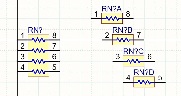
동일한 저항 네트워크가 왼쪽에는 단일 파트로, 오른쪽에는 4개의 개별 파트로 표시되어 있습니다.
멀티 파트 컴포넌트 작업 시 참고 사항:
-
회로도 심볼 편집기에서 메인 메뉴의 Tools » New Part 명령을 사용해 현재 컴포넌트에 다른 파트를 추가합니다. 또는 Active Bar에서
 버튼을 클릭하거나, 디자인 공간에서 마우스 오른쪽 버튼을 클릭한 뒤 컨텍스트 메뉴에서 Tools » New Part를 선택합니다. 새 파트가 컴포넌트에 추가되며, 해당 파트의 빈 시트가 열리고 디자인 창에서 활성화됩니다. 이 시트를 사용해 파트의 그래픽 표현을 구성할 프리미티브를 추가합니다.
-
아래와 같이 SCH Library 패널을 사용해 멀티 파트 컴포넌트의 파트 간 이동을 할 수 있습니다.
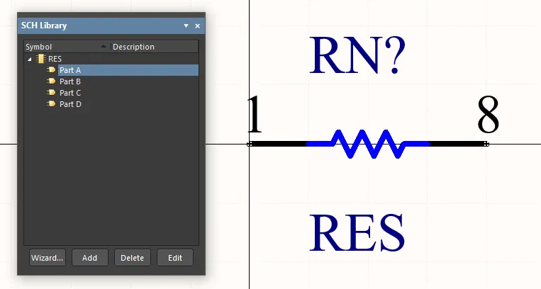
또한 디자인 공간의 오른쪽 클릭 메뉴에서 Tools » Next Part 및 Tools » Previous Part 명령을 사용해 다음 파트 또는 이전 파트를 표시할 수 있습니다.
-
현재 문서에서 열려 있는 멀티 파트 컴포넌트에서 활성 파트를 제거하려면, 메인 메뉴에서 Tools » Remove Part 를 선택하거나 오른쪽 클릭 후 컨텍스트 메뉴에서 Tools » Remove Part 를 선택합니다. 또한 SCH Library 패널에서 멀티 파트 컴포넌트의 파트를 직접 제거할 수도 있습니다.
제거된 컴포넌트 파트는 Undo 명령으로 복원할 수 없습니다.
-
컴포넌트 파트가 약간씩 다르다면, 파트 간에 내용을 복사/붙여넣기한 뒤 예를 들어 새 파트에서는 핀 정보만 업데이트할 수 있습니다.
-
회로도 심볼 편집기는 컴포넌트당 파트 수에 제한이 없으며, 컴포넌트 수준의 Alternate Display Mode feature를 사용하면 각 파트가 서로 다른 그래픽 표현을 지원할 수도 있습니다. 또한 멀티 파트 컴포넌트는 정의된 Normal 및 Alternate Mode를 통해 단 하나의 컴포넌트만으로 단일 심볼(모든 파트) 또는 다중 심볼(각 파트)로 표현할 수 있습니다 – learn more.
-
멀티 파트 컴포넌트의 설계자에는 각 파트를 식별하기 위한 접미사가 포함됩니다. 접미사는 문자 또는 숫자일 수 있으며, Preferences 대화상자의 Schematic - General page에 있는 Alpha Numeric Suffix 영역에서 설정합니다. 이 옵션은 소프트웨어 설치 환경 설정입니다. 라이브러리나 회로도 파일에 저장되지 않으므로, 설계 파일과 함께 이동하지 않습니다.
-
멀티 파트 컴포넌트는 동종(homogeneous)으로 간주되며, 즉 설계 어노테이션 중에는 모든 파트가 동등하고 어노테이션 과정에서 서로 교체될 가능성이 있습니다. 예를 들어 릴레이 코일이 회로도 시트에서의 상대적 위치에 따라 릴레이 접점 세트와 교체될 수 있습니다. 배치된 컴포넌트에서 특정 파트를 고정하려면, 아래와 같이 Properties 패널에서  를 활성화하십시오.
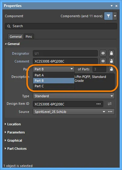
-
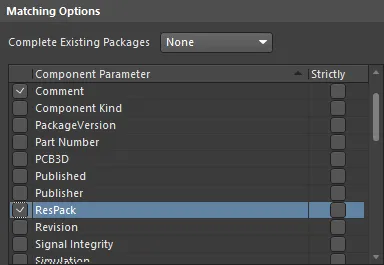
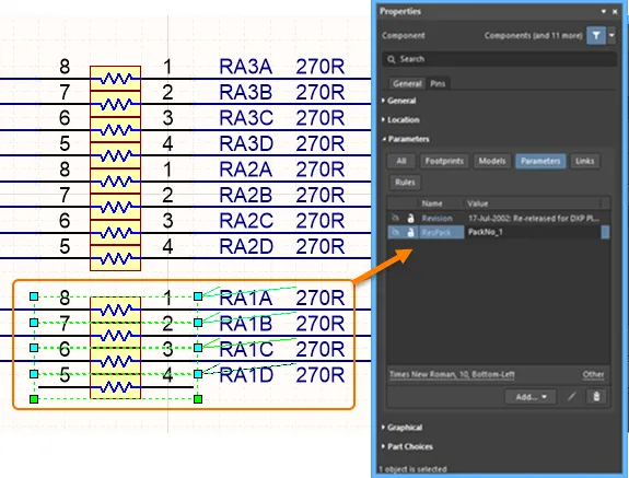
회로도 주석(Annotation) 작업 중에는, 다중 파트(Multi-part) 컴포넌트에 속한 파트들이 Matching Options에 따라 하나의 컴포넌트를 완성하도록 함께 묶이게 됩니다. 이 동작은 Annotate dialog에서 설정한 내용에 따릅니다(아래 그림 참조). 왼쪽의 활성화된 체크박스는 파트들이 함께 패킹(pack)되기 위해 서로 일치해야 하는 컴포넌트 속성을 결정합니다. 예를 들어 필터 설계에서 한 쌍의 OP Amp처럼, 특정 파트들이 동일한 물리 컴포넌트에 함께 들어가도록 패킹을 제어해야 하지만 수동으로 할당하고 잠그는 방식은 원하지 않는 경우, 해당 컴포넌트에 추가 파라미터를 하나 더 만들고 어떤 파트들을 함께 패킹할지 정의하는 값을 입력하십시오. 아래의 상단 이미지는 Annotate 대화상자의 매칭 옵션을 보여줍니다. 활성화된 파라미터는 다중 파트 컴포넌트 매칭에 사용되며, ResPack 파라미터는 Properties panel(하단 이미지)에 추가되어 저항들을 패키지로 묶는 것을 제어합니다(파트들이 동일한 파라미터 값을 가지면 동일한 물리 컴포넌트로 함께 패키징될 수 있음). Strictly 옵션에 유의하십시오. 이 옵션이 활성화되어 있으면, 패킹될 파트는 must 이 파라미터를 포함해야 합니다. 서로 다른 유형의 다중 파트 컴포넌트들에 대해 패키징을 제어하고 있다면 이 옵션에 주의해야 합니다. Strictly is enabled 상태라면, 그들 모두가 해당 파라미터를 포함해야 합니다.
-
PCB 파트 스와핑(Part Swapping)은 파트가 다중 파트 컴포넌트로 정의된 컴포넌트에서만 수행할 수 있습니다. 자세한 내용은 Pin Pair and Part Swapping 문서를 참고하십시오.
-
전원 핀을 정의하려면, 해당 컴포넌트에 추가 파트를 하나 생성한 뒤 그 파트에 VCC 및 GND 핀을 배치할 수 있습니다. 재-주석(re-annotation) 중 어떤 게이트와도 스와핑되지 않도록 하려면 Properties panel에서
 option을 활성화하는 것을 잊지 마십시오.
Display Modes – 동일 컴포넌트의 다양한 표시 방식
소프트웨어는 동일한 컴포넌트에 대해 서로 다른 표시 표현(디스플레이 표현)을 지원합니다. 이러한 표현에는 DeMorgan 표현이나 IEEE 표현처럼 컴포넌트의 그래픽 표현이 서로 다를 수 있습니다. 또는 예를 들어, 어떤 고객은 저항을 직사각형으로 그리는 것을 선호하고, 다른 고객은 물결선 형태를 선호할 수도 있습니다.
이러한 각 표현을 디스플레이 Mode라고 합니다. 파트의 대체 뷰(Alternate view)가 추가되어 있다면, 회로도 심볼 편집기에서 메인 메뉴의 Tools » Mode 하위 메뉴와 Mode 툴바의 Mode 드롭다운에서 대체 모드를 선택하여 편집용으로 표시할 수 있습니다. 활성 컴포넌트의 현재 그래픽 표현은 메인 메뉴의 해당 항목 옆 또는 Mode toolbar의 Mode drop-down 목록에서 활성화된 ‘체크(tick)’ 아이콘으로 표시됩니다. 단, 메뉴와 툴바에는 처음 20개의 Alternate 그래픽 모드만 나열됩니다.
메인 메뉴 또는 툴바 드롭다운에서 일반(Normal) 모드나 대체(Alternate) 모드를 선택하는 것 외에도, 메인 메뉴의 Tools » Mode » Previous 및 Tools » Mode » Next 명령( Mode toolbar의  및
및  버튼)을 사용하여 활성 컴포넌트의 이전/다음 모드를 표시할 수도 있습니다.
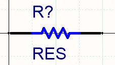
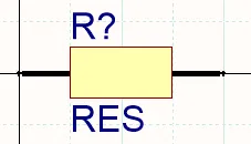

두 개의 디스플레이 모드로 생성된 저항. 라이브러리 편집기에는 모드를 추가/제거하고 모드 간 이동에 사용할 수 있는 Mode 툴바가 포함되어 있습니다.
대체 뷰 모드를 추가하려면, 회로도 심볼 편집기의 디자인 창에 컴포넌트 파트가 표시된 상태에서 Tools » Mode » Add를 선택하거나 Mode toolbar의  버튼을 클릭하십시오.
 Alternate N 디스플레이를 위한 빈 시트가 표시됩니다(N 는 1-255 범위에서 다음으로 사용 가능한 번호). 일반적으로 Normal mode에서 생성한 파트를 복사한 다음 새 Alternate mode에 붙여넣습니다. Edit » Copy 및 Edit » Paste을 사용하여 Normal mode를 Alternate mode. 로 복사/붙여넣기 하십시오. 이렇게 하면 올바른 핀 세트를 확보할 수 있으며, 필요에 따라 그래픽 요소를 수정하고 핀 위치를 조정할 수 있습니다.
현재 대체 모드의 이름을 변경하려면, 메인 메뉴에서 Tools » Mode » Rename command를 선택하거나 Mode toolbar에서 Rename 를 클릭하십시오. 명령을 실행하면 Rename Alternate Representation dialog가 나타납니다. 선택한 심볼의 새 이름을 입력하고 OK를 클릭하십시오. 그러면 이 대체 모드는 메인 메뉴와 Mode toolbar에서 정의한 이름으로 표시됩니다.
활성 컴포넌트의 현재 그래픽 표현(모드)을 제거하려면, 메인 메뉴에서 Tools » Mode » Remove command를 선택하거나 Mode toolbar의  버튼을 클릭하십시오. 컴포넌트에 존재하는 어떤 그래픽 표현(Normal 및 Alternate)도 제거할 수 있습니다. 컴포넌트에 하나 이상의 Alternate 표현이 있고 Normal 표현을 제거하면, 첫 번째 Alternate(Alternate 1)가 Normal 표현이 됩니다. 다른 모든 Alternate는 그에 맞게 번호가 다시 매겨집니다. 컴포넌트에 Alternate 표현이 없는데 Normal 표현을 제거하면, 확인 대화상자가 라이브러리에서 컴포넌트를 제거할지 확인을 요청하며, Yes 를 클릭하면 라이브러리에서 해당 컴포넌트가 사실상 삭제됩니다.
필요한 모드는 라이브러리에서 회로도 시트로 컴포넌트를 배치할 때, Properties panel의 Graphical 영역에 있는 Mode selector를 사용하여 선택합니다. 기본 배치 모드는 라이브러리가 마지막으로 저장될 때 라이브러리 편집기에 표시되어 있던 모드입니다.
각 모드는 동일한 핀 세트를 포함해야 합니다. 그렇지 않으면 프로젝트 검증 시 경고가 생성됩니다. 이는 해당 컴포넌트에 연결된 각 풋프린트에 대해 pin-to-pad mappings를 한 세트만 정의할 수 있기 때문입니다. 핀은 각 모드에서 동일한 위치에 있을 필요는 없습니다.
대체 모드가 있는 다중 파트 컴포넌트 사용
Altium Designer는 정의된 Normal 및 Alternate Modes를 통해, 단 하나의 컴포넌트만 사용하면서 다중 파트 컴포넌트를 단일 심볼(모든 서브 파트) 또는 다중 심볼(각 개별 서브 파트당 하나)로 표시하는 것을 지원합니다. 예를 들어 듀얼 OP Amp 컴포넌트는 한 디스플레이 모드에서는 두 개의 심볼로, 다른 디스플레이 모드에서는 하나의 심볼로 표현될 수 있으며(아래 이미지 참조), 이 경우 단일 심볼 디스플레이 모드에서는 두 번째 파트에 프리미티브가 존재하지 않게 됩니다.
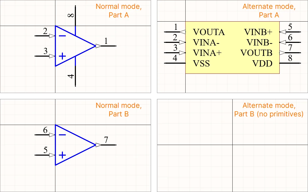
회로도 심볼 편집기에서 프리미티브가 없는 파트는 SCH Library panel에서 볼 수 있는 심볼 파트 목록에서, 프리미티브가 있는 모든 파트 아래에 나열되어야 합니다.
컴포넌트 보고서 생성
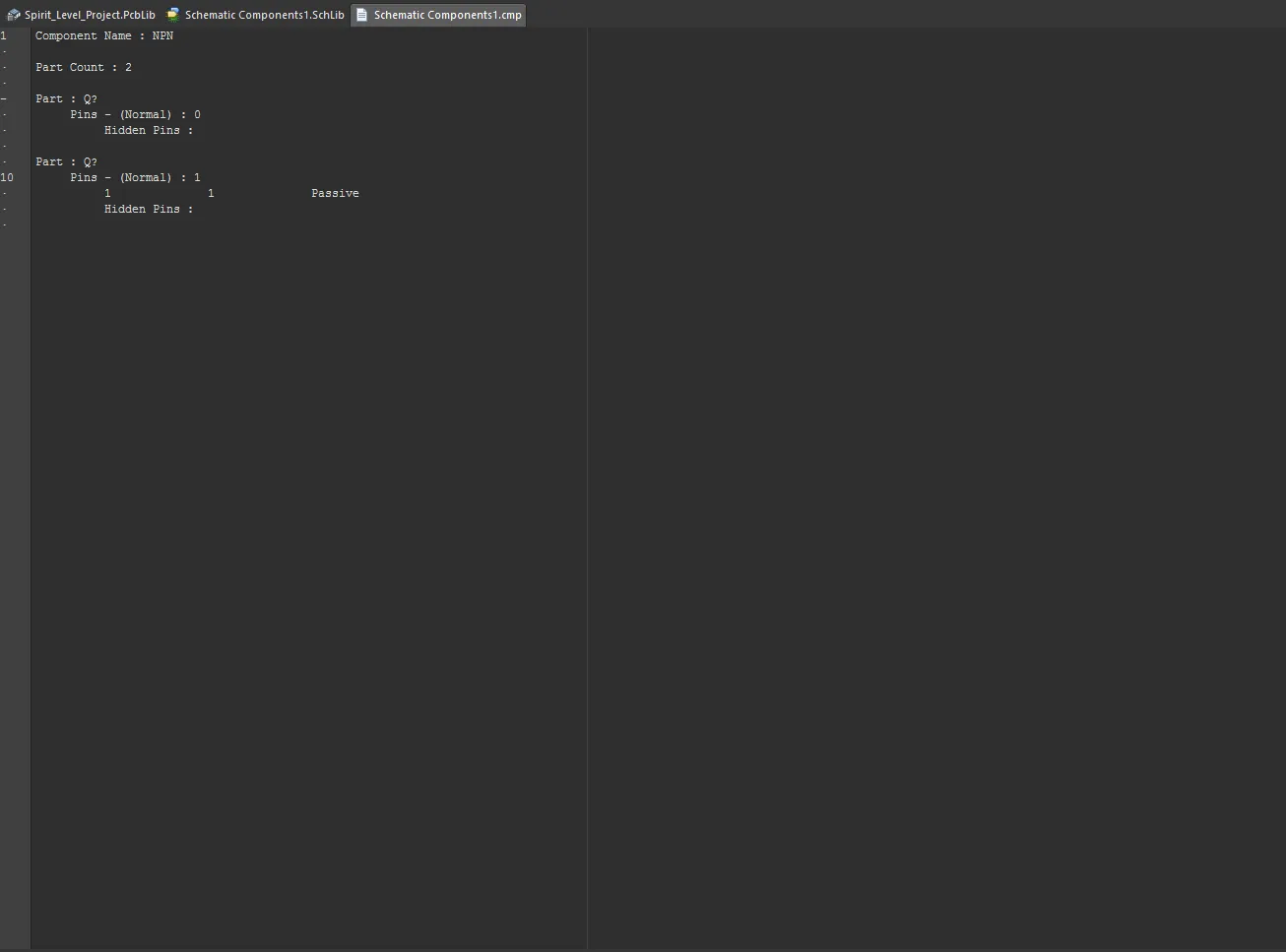
Component Report 는 활성 심볼에 대한 정보를 나열합니다.
-
Reports » Component를 선택합니다(단축키 R, C).
-
<LibraryName>.cmp라는 제목의 보고서가 활성 문서로 열립니다. 파일에는 컴포넌트 이름과 컴포넌트에 포함된 파트 수가 포함됩니다. 각 파트에 대해, 각 그래픽 표현(Normal 및 모든 Alternate)에 대한 핀 상세 정보가 제공됩니다.
-
보고서를 닫고 회로도 편집기 디자인 공간으로 돌아갑니다.
점퍼(Jumper) 컴포넌트 지원
점퍼(와이어 링크라고도 함)는 배선을 점퍼 컴포넌트로 대체할 수 있게 해주며, 이는 단면 보드를 성공적으로 설계하는 데 종종 필수 요소입니다. Altium Designer는 Jumper라는 특수 컴포넌트 타입을 통해 점퍼 컴포넌트 사용을 지원합니다.
점퍼 풋프린트를 PCB에 직접 배치하는 것부터 시작할 수도 있지만, 권장 워크플로는 회로도에서 시작하는 것입니다. 자세한 내용은 Working with Jumper Components 페이지를 참고하십시오.
회로도 심볼 생성 도구 사용
컴포넌트가 복잡해짐에 따라, 컴포넌트 라이브러리 심볼과 그 핀 데이터를 생성하는 작업은 점점 더 많은 작업을 요구하게 되었습니다. 예를 들어 대규모 BGA 디바이스는 수백 개의 핀을 배치하고 구성해야 하므로, 실용적인 컴포넌트 심볼을 만들기 위해 상당한 시간과 노력이 필요한 경우가 많습니다.
컴포넌트 심볼 생성과 관련된 작업 부담을 줄이기 위해, Altium Designer는 심볼 위저드 인터페이스와 핀 편집기 대화상자를 기반으로 한 고급 Schematic Symbol Generation Tool을 제공합니다. 여기에는 자동 심볼 그래픽 생성, 그리드 핀 테이블, 스마트 데이터 붙여넣기 기능이 포함됩니다.
Altium Designer에서 Schematic Symbol Generation Tool 기능을 사용하려면 Schematic symbol generation tool 소프트웨어 확장(extension)을 설치해야 합니다. 이 확장은 기본적으로 Altium Designer와 함께 설치됩니다. 수동으로 설치하거나 제거할 수 있습니다.
확장 관리에 대한 자세한 내용은 Extending Your Installation 페이지를 참고하십시오(Altium Designer Develop, Altium Designer Agile, Altium Designer).
심볼 생성
Schematic Symbol Generation Tool은 회로도 라이브러리 편집기에서 메인 메뉴의 Tools » Symbol Wizard command를 선택하여 사용할 수 있습니다. 또한 Component Editor in its Single Component Editing mode를 사용해 Workspace 컴포넌트를 생성할 때에도, 심볼 모델 아래 버튼의 드롭다운 아이콘을 클릭하고 메뉴에서 Wizard 를 선택하여 접근할 수 있습니다.
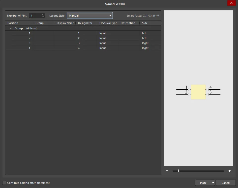
도구를 사용해 새 컴포넌트 심볼을 만들려면, 먼저 활성 라이브러리 문서에 새 컴포넌트를 추가합니다. 그런 다음 명령을 실행하면 열리는 도구 인터페이스, 즉 Symbol Wizard 대화상자에서 새 심볼을 개발할 수 있습니다. 이 대화상자를 사용해 핀 개수, 핀 배치, 핀 데이터 등 필요한 컴포넌트 심볼을 대화형으로 정의합니다.
-
Number of Pins - 원하는 핀 개수를 직접 입력하거나 위/아래 화살표를 사용해 증가/감소시킵니다.
-
Layout Style - 핀 위치가 자동으로 할당되는 미리 정의된 패턴 세트에서 선택합니다. 드롭다운에서 선호하는 배열을 선택하세요. 그러면 오른쪽의 Preview 이미지와 Side 열의 데이터가 그에 맞게 업데이트됩니다. 선택 항목에는 다음이 포함됩니다:
Grid
열 머리글을 클릭하면 해당 열을 기준으로 그리드 데이터를 정렬합니다. 다시 클릭하면 오름차순/내림차순이 전환됩니다.
테이블 내에서는 표준 복사-붙여넣기 기법을 사용해 한 셀 그룹의 데이터를 다른 셀 그룹으로 채울 수 있습니다. 예를 들어 열에서 셀 3개를 선택해 데이터를 복사(right-click – Copy)한 다음, 대상 셀 3개를 선택해 데이터를 붙여넣을(right-click – Paste) 수 있습니다. 같은 기법을 사용해 스프레드시트, 텍스트, PDF 파일 등 외부 소스에서 데이터 선택을 복사해 올 수도 있습니다.
그리드 셀은 단일 또는 다중으로 수동 편집할 수 있습니다. 표준 Ctrl+click 및 Shift+click 기법을 사용하세요. 드롭다운 메뉴가 있는 열에서 여러 셀을 편집하려면 원하는 셀 범위를 선택한 다음, 선택된 셀 중 하나에서 새 메뉴 항목을 선택합니다.
Right-click Menu
-
Move Up - 선택한 데이터를 한 행 위로 이동하는 데 사용합니다.
-
Move Down - 선택한 데이터를 한 행 아래로 이동하는 데 사용합니다.
-
Copy - 선택한 데이터를 클립보드로 복사하는 데 사용합니다.
-
Paste - 클립보드에 가장 최근 복사된 데이터를 커서 위치에 붙여넣는 데 사용합니다.
-
Smart Paste - Pin Data Smart Paste 대화상자를 열어 외부 소스 데이터의 여러 열을 그리드의 해당 열로 복사합니다. 대화상자에서 열 데이터와 구분자를 구성한 다음 Paste을(를) 클릭합니다. Smart Paste에 대해 더 알아보세요.
-
Clear - 핀 데이터를 삭제하는 데 사용합니다.
Preview
이 영역은 심볼 그래픽의 미리보기를 표시하며, 현재 설정과 핀 데이터를 동적으로 반영합니다. 슬라이더 바 또는 - 및 + 을(를) 사용해 그래픽을 확대/축소합니다.
Additional Controls
-
Continue editing after placement - 체크하면 컴포넌트를 배치한 후에도 대화상자가 활성 상태로 유지되어(추가 편집 가능) 계속 작업할 수 있습니다.
-
Place - 완성된 심볼과 핀 데이터를 배치하는 데 사용합니다. 선택 항목은 다음과 같습니다:
-
Place Symbol
-
Place New Symbol
-
Place New Part
-
Place Symbol
-
Place New Symbol
-
Place New Part
Pasting Pin Data
테이블의 핀 데이터는 여러 셀에 대해 공통 값으로 편집할 수 있지만, 대화상자의 Paste 및 Smart Paste 기능은 외부 소스에서 대량의 서로 다른 데이터를 가져와 모든 셀 데이터를 채우는 고급 방법을 제공합니다.
테이블 내에서는 표준 복사/붙여넣기 기법을 사용해 한 셀 그룹의 데이터를 다른 셀 그룹으로 채울 수 있습니다. 예를 들어 열에서 셀 3개를 선택해 데이터를 복사(우클릭 - Copy)한 다음, 붙여넣을 대상 셀 3개를 선택(우클릭 - Paste)합니다.
같은 기법을 사용해 스프레드시트, 텍스트 파일, PDF 파일 등 외부 소스에서 데이터 선택을 복사/붙여넣기할 수도 있습니다.
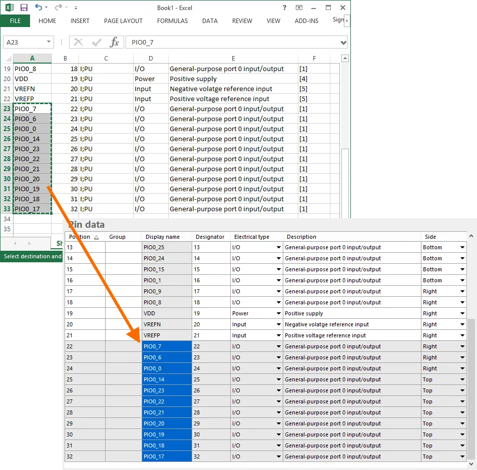 외부 스프레드시트에서 복사한 데이터를 Pin data 테이블에 붙여넣는 예.
Smart Paste
표준 복사/붙여넣기 기법을 넘어, Smart Paste는 자동화된 열 매핑 방식을 사용해 외부 소스에서 여러 열의 데이터를 채울 수 있는 기능을 제공합니다.
Pin data 테이블의 해당 열로 소스 데이터의 여러 열을 복사하려면, 테이블에서 우클릭하고 컨텍스트 메뉴에서 Smart Paste 명령을 선택합니다. 그러면 Pin Data Smart Paste 대화상자가 열리며 소스 데이터로 채워집니다. 다양한 데이터 구분자를 사용할 수 있으며, 소스 데이터에 사용된 구분자와 일치하도록 선택할 수 있습니다.
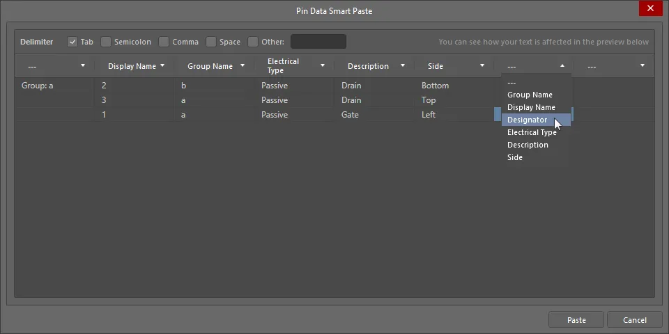
Pin Data Smart Paste dialog
Options and Controls of the Pin Data Smart Paste Dialog
Additional Controls
-
Paste - 클릭하여 Smart Paste 프로세스를 완료합니다. 소스 데이터가 그리드 영역에서 지정한 해당 열로 복사됩니다.
Right-Click Menu
-
Remove Line - 한 줄 위에서 클릭한 다음 이 명령을 선택하면 해당 줄이 제거됩니다. 대화상자의 빈 공간에서 명령을 실행하면 맨 아래 줄이 제거됩니다.
-
Remove Column - 한 열 위에서 클릭한 다음 이 명령을 선택하면 해당 열이 제거됩니다.
Symbol Placement
필요에 맞게 설정과 핀 데이터가 구성되면, 심볼을 활성 라이브러리 컴포넌트의 디자인 공간에 배치할 수 있습니다. 배치는 단일 컴포넌트 기준으로 할 수도 있고, 다중 파트 컴포넌트의 한 섹션으로 배치할 수도 있으며, 이는 대화상자의 Place 버튼에 연결된 컨텍스트 메뉴에서 제공되는 해당 명령을 사용합니다. Continue editing after placement 옵션이 활성화되어 있으면, 컴포넌트/파트를 배치한 후에도 Symbol Wizard 대화상자가 활성 상태로 유지되어(추가 편집 가능) 계속 작업할 수 있습니다.
회로도 라이브러리에서 기존 컴포넌트에 대해 Symbol Wizard 대화상자에 접근하면, 모든 설정과 핀 데이터가 표시되어 추가 변경을 할 수 있습니다. 이 대화상자가 기본 상태로 표시되는 경우는 새 라이브러리 컴포넌트에 사용할 때뿐입니다.
Smart Grid Insert Tool로 회로도 심볼 생성 가속화
SCHLIB List 패널에서 사용할 수 있는 Smart Grid Insert 도구를 사용하면 현재 클립보드 데이터를 Altium Designer 객체 속성에 매핑할 수 있습니다. 이러한 도구는 회로도 심볼 생성 과정을 크게 단순화하며, 몇 단계만으로 스프레드시트, PDF, ASCII 파일 같은 외부 데이터에서 컴포넌트의 핀을 직접 생성할 수 있습니다.
소스 핀 데이터를 Altium Designer로 바로 복사할 수도 있지만, 최적의 결과를 얻기 위해 약간의 사전 준비 작업을 하는 것이 좋습니다. 이를 수행하기에 스프레드시트가 적합합니다. 일반적으로 다음과 같은 몇 가지 단계만 수행하면 됩니다:
-
열 간 매핑을 더 쉽게 하기 위해 헤더 행을 추가합니다. 열 이름을 정확히 동일하게 맞출 필요는 없습니다. Altium Designer는 올바른 매핑을 자동으로 추론하는 데 능숙합니다.
-
Altium Designer가 핀 타입 객체를 생성해야 한다는 것을 알 수 있도록 Object Kind 열을 추가합니다.
-
각 핀의 전기적 타입을 지정하기 위해 Type 열을 추가합니다.
-
X 및 Y 핀 위치를 포함합니다. 스프레드시트는 셀에 값을 채우는 훌륭한 도구를 제공합니다. 예를 들어 Microsoft Excel에서 우클릭한 채 드래그하여 셀 집합을 선택하면 원하는 숫자 수열을 지정할 수 있어, 회로도 라이브러리에서 핀 간격을 쉽게 맞출 수 있습니다.
FPGA와 같이 핀 수가 많고 섹션이 규칙적으로 나뉘는 부품은 Altium Designer에서 멀티파트(Multipart) 컴포넌트로 구현하기에 적합합니다. 가장 쉬운 방법은 Altium Designer 컴포넌트의 첫 번째 파트에 모든 핀을 만든 다음, 핀 블록을 잘라내어 다른 파트에 복사/붙여넣기 하는 것입니다.
핀을 깔끔하게 ‘파트 단위로 바로 쓸 수 있는’ 그룹으로 만들려면, 스프레드시트에서 각 파트의 핀들 사이에 빈 행을 두세 줄 정도 남겨두는 방법을 권장합니다. 이렇게 하면 좌표 값을 어디서 다시 시작해야 하는지 쉽게 파악할 수 있을 뿐 아니라, 넓은 범위에 X, Y 값을 자동으로 추가한 뒤 빈 행에 들어간 중복 X, Y 값만 제거할 수도 있습니다. 그러면 삭제된 위치에는 핀이 생성되지 않아, 파트별 그룹이 보기 좋게 간격을 두고 배치됩니다.
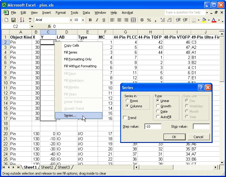
스프레드시트의 도구를 사용해 핀에 적절한 X, Y 좌표를 추가합니다.
스프레드시트에서 필요한 셀을 선택해 복사합니다. 선택 범위에 불필요한 열이 포함되어 있어도 괜찮습니다. Smart Grid 도구가 이런 열은 무시할 수 있습니다.
Altium Designer에서 SCHLIB List 패널 안을 마우스 오른쪽 버튼으로 클릭하고 메뉴에서 Smart Grid Insert를 선택해 Smart Grid Insert 대화상자를 엽니다. 소스 데이터에 헤더 행이 포함되어 있으면 Altium Designer가 오브젝트 종류를 자동으로 식별하려고 시도한 뒤, 생성될 오브젝트 목록을 구성합니다. 여기서 기억할 점은, 열 매핑을 하기 전에는 생성될 오브젝트 목록이 현재 Altium Designer의 기본 핀 오브젝트 속성을 따른다는 것입니다. 예를 들어 모든 핀을 180도 방향에 길이 20으로 배치하고 싶다면, Smart Grid 과정을 시작하기 전에 Altium Designer에서 기본값을 먼저 설정해 두세요. 그러면 스프레드시트에 해당 설정을 넣거나, 생성 후 Altium Designer에서 다시 편집할 필요가 없습니다. 기본값 설정 방법이 헷갈리나요? 메뉴에서 Place » Pin를 선택한 다음, 핀을 배치하기 전에 Tab를 눌러 기본값을 편집하고, 핀 하나를 배치한 뒤 그 핀을 삭제하면 됩니다.
헤더 행을 포함했을 때의 또 다른 큰 장점은 Automatically Determine Paste 버튼을 사용할 수 있다는 점입니다. 이 기능은 매우 유용한데, 생성될 오브젝트의 필드와 소스 데이터의 열 제목을 검색/비교해 매핑 방식을 지능적으로 선택해 줍니다. 자동 매핑이 하나 잘못되더라도 걱정하지 마세요. Undo Paste 버튼으로 매핑된 열을 되돌릴 수 있습니다. 수동으로 매핑하려면 소스 데이터의 열과 생성될 오브젝트의 해당 열을 각각 선택한 다음 Paste Column 버튼을 클릭합니다.
OK를 클릭하는 즉시 생성된 오브젝트 세트가 디자인 공간에 나타납니다. 각 파트에 적절한 바디를 추가한 다음, 잘라내기/붙여넣기로 개별 파트를 만들면 심볼이 완성됩니다.
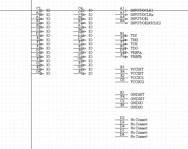
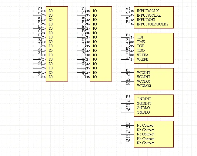
Smart Grid로 삽입된 핀, 그리고 컴포넌트 바디가 추가된 파트들.