Altium Designer의 새로운기능

Now reading version 21.0. For the latest, read: Altium Designer의 새로운기능 for version 25
 

This page details the improvements included in the initial release of Altium Designer 21, as well as those added in subsequent updates. Along with delivering a range of improvements that develop and mature the existing technologies, each update also incorporates a large number of fixes and enhancements across the software based on feedback raised by customers through the AltiumLive Community's BugCrunch system, helping you continue to create cutting-edge electronics technology.

You have the choice to continue with your current version, update your current version, or install Altium Designer 21 alongside your current version to access the latest features. Your current version can be updated from within the software in the Extensions and Updates view. If you prefer to install Altium Designer 21 alongside your current version, visit the Altium Downloads page to download the installer then choose New Installation on the Installation Mode page of the installer.

Free Trial!

If you like what you see but are not yet a customer, why not take Altium Designer for a test drive? By filling out a simple form, you can try Altium Designer for free with 15 days of access to the full software. That's right, the ability to evaluate the full Altium Designer experience with no technical limitations, giving you unfettered access to the world's finest PCB design product. Click the link below, fill out the form, and see for yourself why more engineers and designers choose Altium than any other product available!

Altium Designer Free Trial

This page details the improvements included in the initial release of Altium NEXUS 4, as well as those added in subsequent updates. Along with delivering a range of improvements that develop and mature the existing technologies, each update also incorporates a large number of fixes and enhancements across the software based on feedback raised by customers through the AltiumLive Community's BugCrunch system, helping you continue to create cutting-edge electronics technology.

You have the choice to continue with your current version, update your current version, or install Altium NEXUS 4 alongside your current version to access the latest features. Your current version can be updated from within the software in the Extensions and Updates view". If you prefer to install Altium NEXUS 4 alongside your current version, visit the Altium Downloads page to download the installer then choose New Installation on the Installation Mode page of the installer.

Altium Designer 21.9

Released: 30 November 2021 – Version 21.9.2 (build 33) - Hot Fix 1

Released: 22 November 2021 – Version 21.9.1 (build 22)

Release Notes for Altium Designer Version 21.9 

Welcome to Update 9 for Altium Designer 21. This update to Altium Designer continues to deliver improvements and enhancements to the software's core technologies, while also addressing many of the ideas raised by customers through the AltiumLive Community's BugCrunch system.

Welcome to Update 9 for Altium NEXUS 4. This update to Altium NEXUS continues to deliver improvements and enhancements to the software's core technologies, while also addressing many of the ideas raised by customers through the AltiumLive Community's BugCrunch system.

Schematic Capture Improvements in Update 9

Intuitive Parameter Inheritance

Parameters are an essential feature for annotating your schematic design. They allow you to include placeholders for text strings on the template or the schematic sheet that can then be given a value at a later stage. Parameters can be added to the project, a schematic sheet (document), or a variant.

The previous behavior was that if a parameter name is duplicated, for example, when the same parameter is used in the project and also in a sheet, they are resolved hierarchically in the order of the Document parameter, the Variant parameter, then the Project parameter. This behavior meant that it was not possible to define the same Project parameter as an existing Document parameter because the value of the Document parameter would always be displayed, and if the Document parameter had no value, nothing would be displayed.

This release sees the introduction of support for Document parameters that have no value to inherit the value from a Variant or Project parameter that has the same name. For example, now you can add the parameter Engineer to the Project (or the Variant) and define the value once rather than defining it on every schematic sheet. To indicate that a parameter value is inherited, it is displayed in gray italics. Typing repeated values for the different parameter 'levels is no longer required because if the value of a parameter is empty, the appropriate value is automatically entered.

As part of this update, the order of parameter priority has also changed. When the same parameter exists in different locations, Variant parameters now have the highest priority (when the variant that holds the parameter is the active variant).

Notes about this feature:

  • The priority of parameters, from the highest to lowest, is:
    1. Variant parameter (when the variant that holds the parameter is the active Variant in the Projects panel)
    2. Document parameter
    3. Project parameter
  • When the same parameter exists in more than one location (Variant, Document, Project) and the Document parameter has no value, the parameter's value is inherited from the highest priority parameter that has a value.
  • When a Document parameter value is inherited (is being sourced from a Variant or Project parameter of the same name) the value is displayed in the Properties panel in gray italics, indicating that the parameter value is inherited. The Document parameter value can still be edited, as required.
  • The concatenation of parameter values that rely on this priority behavior is also supported. For example, the following text string (where Engineer is a Variant, Document & Project parameter and ApprovedBy is a Document & Project parameter but the Document parameter has no value):

='Document: '+DocumentName +', Designed by: '+Engineer+', Approved: '+ApprovedBy+', Date: '+ModifiedDate

displays the text:

Document: SpiritLevel.SchDoc, Designed by: Variant Engineer, Approved: Project Engineer, Date: 28-Sep-21

This feature is in Open Beta. If required, it can be turned off by disabling the Schematic.ShowRecursiveParametersInIPP option in the Advanced Settings dialog.

Direction of Additional Nets and Ports

When adding additional ports on a schematic or pins on a schematic library, they are now placed as follows:

  • Vertically for horizontal ports and pins.

  • Horizontally for vertical ports and pins.

PCB Design Improvements in Update 9

New 'Obey Polygon Cutout' Option for Hatched Polygons

The Obey Polygon Cutout option has been added to the Polygon Pour mode of the Properties panel. The option is enabled by default for newly-created hatched polygons. This new option allows you to choose the method you want to be used when pouring hatched polygons around cutouts.

Reduced Delay when Selecting Primitives

This feature reduces a delay when using the mouse to select overlapping primitives.

This feature is in Open Beta. If required, it can be turned off by disabling the PCB.Selection.OptimizeDelayOnClick option in the Advanced Settings dialog.

Define the Paste Mask Expansion as a Percentage

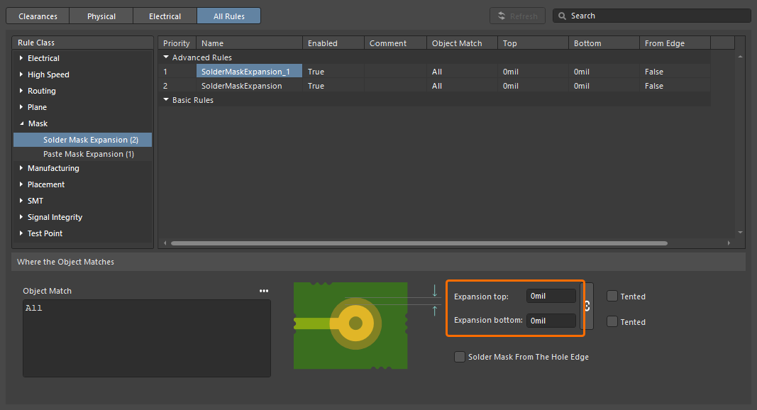
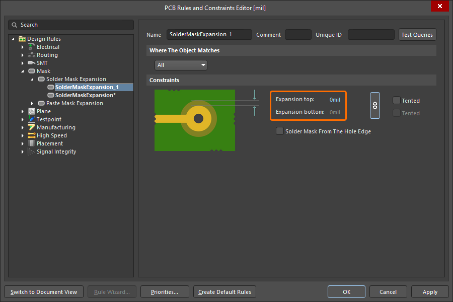
Many designers prefer to specify the paste mask as a percentage of the pad area instead of an absolute expansion or contraction value. This release sees the introduction of a new Measurement Method option in the PasteMaskExpansion design rule. When the option is set to Percent, the Expansion is defined as a percentage of the pad area.

Set the Expansion as follows:

  • Expansion = 0 - the paste mask opening is the same size as the pad
  • Expansion < 0 - enter a negative value to define a paste mask area that is <Value> percent smaller than the pad area
  • Expansion > 0 - enter a positive value to define a paste mask area that is <Value> percent larger than the pad area

The display and editing of Paste Mask Expansion as a percentage was also added to the following areas of the software:

  • PCB List panel 

  • Pad Template Editor (enter the value with the % symbol into the edit box)

  • Pad mode of the Properties panel (enter the value with the % symbol into the edit box)

This feature is in Open Beta. If required, it can be turned off by disabling the PCB.PasteMask.Percentage option in the Advanced Settings dialog.

Display the Paste Mask in 3D

This feature allows you to view the contents of the Paste Mask layers when the PCB is in 3D mode. When the option is enabled, additional Top Paste Mask and Bottom Paste Mask controls are included in the 3D Settings region of the View Options tab of the View Configuration panel. Use the controls to configure the transparency of the contents of the Paste Mask layers. The Paste Mask is rendered at the same thickness and in the same Z-plane as the Solder Mask layers.

This feature is in Open Beta. If required, it can be turned off by disabling the PCB.PasteMask.Displaying3D option in the Advanced Settings dialog.

Accurate Layer Drawing

In previous versions, the PCB editor always displayed multi-layer objects in the multi-layer layer color regardless of the current layer drawing order or the visibility state of the multi-layer. In this release, the behavior of the multi-layer has been made intuitive and predictable.

  • Accurate color usage in single-layer mode - switch to single-layer mode and the multi-layer objects are automatically displayed in the active layer color.
  • The multi-layer can now be turned off - multi-layer objects are then rendered in the signal layer color.
  • The layer drawing order is obeyed - if the Current Layer is configured to be above the Multi-layer, all multi-layer objects are rendered in the active layer color.
  • If a via or a multi-layer pad has Top-Middle-Bottom or Full Stack mode enabled in its properties, it is always rendered in the active layer color.

This feature is in Open Beta. If required, it can be turned off by disabling the PCB.LayerDrawingOrder.ProperMultilayer option in the Advanced Settings dialog.

Data Management Improvements in Update 9

Comment Assignment Enhancement

A 'mention' reference can now be added within a comment for any other user or role registered with the connected Workspace by entering the @ character or by clicking the comment's button (). Select a name/email from the drop-down to add the user (team member) reference to the comment, and also as an Assign To entry. Uncheck the latter option if you do not want the comment to be regarded as specifically assigned to that user or group. A Role group (e.g., Engineers), and, therefore, its constituent users, may also be added as a mention and/or assignment.

If a mentioned user does not have access to the current project, you will be invited to share it with that user. This option is available if you are the project owner or a Workspace administrator. User Access Rights are granted through the  Share dialog; the user will receive an email notifying them of the shared access. The project will not be shared if you cancel the Share dialog, however, the comment will be placed as usual.

Library Health View

When browsing the content of a connected Workspace, the Explorer panel now includes the Library Health view from where you can run health checks and inspect component health issues. Select the Library Health entry in the Server Folders region of the panel to access this view.

The top region of the view provides a summary of the health of your components since last running a health check. Below that region are the health check analyses that are supported and are gathered into various Issue Themes. Click on a health check analysis tile to view a more detailed description of the check with steps to resolve issues (where available), as well as a detailed listing of all components failing that health check.

Circuit Simulation Improvements in Update 9

Added Measurement Data

Measurements are a collection of quantities that characterize the behavior and quality of a circuit. The values of the measurements are calculated according to the specified rules by evaluating the characteristics of the waveforms in the circuit. Examples of measurements are bandwidth, gain, rise time, fall time, pulse width, frequency, and period. There are no limits to the number of measurements you can define. The Measurement tab and data has been added to the Output Expressions dialog and the Sim Data panel. You can add, view and update measurements including the type, value and name.

This feature is in Open Beta. If required, it can be turned off by disabling the Simulation.Measurements option in the Advanced Settings dialog.

Added Option to Simulation - General Preferences

Added the Always Generate Model Symbol for Manufacturer Part Search Panel Using Simulation Model Description option to the Simulation - General page of the Preferences dialog. When the option is enabled, model symbols are always generated using the simulation model description in the Manufacturer Part Search panel when placing a component on a schematic.

Altium Designer 21.8

Released: 21 October 2021 – Version 21.8.1 (build 53)

Release Notes for Altium Designer Version 21.8 

Welcome to Update 8 for Altium Designer 21. This update to Altium Designer continues to deliver improvements and enhancements to the software's core technologies, while also addressing many of the ideas raised by customers through the AltiumLive Community's BugCrunch system.

Welcome to Update 8 for Altium NEXUS 4. This update to Altium NEXUS continues to deliver improvements and enhancements to the software's core technologies, while also addressing many of the ideas raised by customers through the AltiumLive Community's BugCrunch system.

Circuit Simulation Improvements in Update 8

X-Axis Expression

Added the ability to set the X-axis expression in the Add Output Expression dialog. Use the Expression X and Expression Y fields to configure the individual expressions. 

Zooming Plots Separately

The option to zoom plots separately is now provided in the Document Options dialog (Tools » Document Options from a *.sdf file). Enable the Zoom Plots Separately option in the dialog to use the new feature.

New X-Axis Settings Dialog

X-Axis settings were added to the Plot menu to allow independent zooming. Click Plot » Format X-Axis to open the new X Axis Settings dialog.

The options in the new dialog were previously located in the Chart Options dialog. 

Added Smart Pin Mapping in the Sim Model Dialog

Smart pin mapping has been added as the default in the Pin Mapping region of the Sim Model dialog. 

Altium Designer 21.7

Released: 29 September 2021 – Version 21.7.2  (build 23)

Release Notes for Altium Designer Version 21.7

Welcome to Update 7 for Altium Designer 21. This update to Altium Designer continues to deliver improvements and enhancements to the software's core technologies, while also addressing many of the ideas raised by customers through the AltiumLive Community's BugCrunch system.

Welcome to Update 7 for Altium NEXUS 4. This update to Altium NEXUS continues to deliver improvements and enhancements to the software's core technologies, while also addressing many of the ideas raised by customers through the AltiumLive Community's BugCrunch system.

Schematic Capture Improvements in Update 7

Warning When Opening a Schematic Saved in a Newer Version

Implemented a 'Schematic was done in newer version' warning to notify users that new functionalities were introduced between the version of Altium Designer that was used to create the schematic, and the version used to open the schematic document. This feature functions in the same way as the PCB editor version warning.

Quickly Open the Last Active Sheet

This feature is in Open Beta and is available when the UI.SmartDocumentSwitching option is enabled in the Advanced Settings dialog.

The last active schematic sheet is now displayed after clicking on the text of the schematic document tab. This is very useful when there are a large number of schematic sheets opened that are included in the drop-down of the tab. 

Cross-Reference Options

Cross-Reference settings have been moved from the Schematic - General page of the Preferences dialog to the Options tab of the Project Options dialog with additional options that allow you to select the supported object(s). 

Use the Sheet Style and Location Style drop-downs to set the cross-referencing options. Enable the required supported objects.

Port to Port Cross References

This feature is available by enabling the Schematic.EnhancedCrossReferences option in the Advanced Settings dialog. This feature is in Open Beta with a default value of 0.

It also requires the Schematic.UseAutomaticCrossReferences option to be enabled.

Adding cross-references to the project allows you to easily follow the connective flow of nets between the schematic sheets in a project. Building on the support for automatically creating and updating cross-references recently introduced by the Schematic.UseAutomaticCrossReferences option, this new advanced option brings support for cross-references in a hierarchical project.

Enable the Automatic Cross References option in the Project Options dialog then use the right-click context menu to Jump to your choice of target location anywhere in the hierarchy.

Use the Jump to command to jump to a matching Port anywhere in the design hierarchy.Use the Jump to command to jump to a matching Port anywhere in the design hierarchy.

This feature supports three modes described below that are enabled by setting the Value of the advanced option.

  • 0 - Legacy mode - use this value to enable the following relations:
    1. Port <-> Sheet Entry 
    2. Off Sheet <-> Off Sheet
  • 1 - Enhanced mode - use this value to enable the following relations:
    1. Off Sheet <-> Off Sheet
    2. Port <-> Port
  • 2 - Enhanced + Legacy mode - use this value to enable the following relations:
    1. Off Sheet <-> Off Sheet
    2. Port <-> Port
    3. Port <-> Sheet Entry

     This mode also enables Port Actions >> Jump to Port.

For this release, both Port-to-Port and Port-to-Sheet Entry cross-references are included as 'Jump to' locations. This will be made configurable in a future release.

Added User Control of the 'Show More' Feature for Component Parameters

This feature is controlled by the Schematic.UI.ShowMoreOrLessParameters option in the Advanced Settings dialog. This feature is in Open Beta with a default value of on, meaning the Show More/Show Less controls are displayed in the Properties panel. Disable the option to always show all parameters.

The Show More feature simplifies the display of component parameters by reducing the list to only display those parameters that have been set as a favorite. However, you might prefer to always have all parameters displayed in the Component mode of the Properties panel.

The default behavior is to automatically hide parameters that are not marked as favorites. Hover the cursor over the image to demonstrate.The default behavior is to automatically hide parameters that are not marked as favorites. Hover the cursor over the image to demonstrate.

To support this, when the new option is disabled, the Show More/Show Less feature is disabled, resulting in all of the component parameters always being displayed in the Component mode of the Properties panel.

The Show More/Show Less feature is disabled when the advanced option is disabled.The Show More/Show Less feature is disabled when the advanced option is disabled.

PCB Design Improvements in Update 7

Added Properties Panel Mode for Rooms

The properties of rooms can now be configured and edited in the Properties panel. You can use the new mode to define the name, coordinates and outline vertices of rooms.

The new Room mode of the Properties panelThe new Room mode of the Properties panel

Added Use Paste Option for Pads

This feature, which is enabled by default, can be disabled by toggling the PCB.PasteMask.NoPaste option in the Advanced Settings dialog. This feature is in Open Beta.

A Use Paste option has been added to the PasteMaskExpansion design rule, the Pad mode of the Properties panel, and the Pad Template Editor, alleviating the need to use a suitable negative value to remove Paste. Clear the checkbox to remove the paste from the targeted/selected pad(s).

Data Management Improvements in Update 7

Streamlined Access to the Built-in Version Storage

Altium Designer now provides an enhanced flow that helps you to more easily use the benefits of the built-in Git-based version storage in Altium 365 for local projects. The enhancements are described below.

  • Use the below iteration of the Add to Version Control dialog to connect to an Altium 365 Workspace (if it's available) and make the current project available online if there are no other custom repositories configured. This version of the dialog is accessed by right-clicking on a project name in the Projects panel then selecting History & Version Control » Add Project to Version Control when you are not currently using any workspaces.

  • If a connection within Altium 365 Workspace is available, you also can enable the Version Control option in the Make Available Online dialog after using the Make Project Available Online command accessed from a local project's right-click menu in the Projects panel.

Circuit Simulation Improvements in Update 7

Parameter Sweep Enhancement

The ability to sweep more than two parameters during the Parametric Sweep has been added. 

Added Category for Output Variables

Added Waveforms and Functions drop-downs in the Add Output Expression dialog to allow you to select the required items.

Save X,Y Scale Settings

The X,Y scale settings for plots are now kept during the simulation process for opened and saved .sdf documents. 

New DC and Transient Analysis Supported Variables

The following variables are now supported in DC and Transient Analysis: 

  • Output charge on a capacitor
  • Output conductance on a current switch 
  • Output conductance on a voltage switch
  • Output current for an independent current source model
  • Output power on functional voltage and current sources
  • Output voltage on a capacitor
  • Output voltage on a voltage switch
  • Output voltage on an independent voltage source 
  • Output voltage on the current switch

Features Made Fully Public in Update 7

The following features have been taken out of Open Beta and transitioned to Public in this release:


Altium Designer 21.6

Released: 20 August 2021 - Version 21.6.4 (build 81)
Released: 22 July 2021 – Version 21.6.1 (build 37)

Release Notes for Altium Designer Version 21.6

Welcome to Update 6 for Altium Designer 21. This update to Altium Designer continues to deliver improvements and enhancements to the software's core technologies, while also addressing many of the ideas raised by customers through the AltiumLive Community's BugCrunch system.

Welcome to Update 6 for Altium NEXUS 4. This update to Altium NEXUS continues to deliver improvements and enhancements to the software's core technologies, while also addressing many of the ideas raised by customers through the AltiumLive Community's BugCrunch system.

Schematic Capture Improvements in Update 6

Display Automatic Sheet Numbering

This feature, which is enabled by default, can be disabled by toggling the Schematic.UseAutomaticSheetNumbering option in the Advanced Settings dialog. This feature is in Open Beta.

Added the Show Automatic Sheet Numbering option, which enables you to control the visibility of sheet numbers. The option has been added to the System - Projects Panel page of the Preferences dialog and the Projects panel settings. 

Improved Schematic Cross References

This feature, which is enabled by default, can be disabled by toggling the Schematic.UseAutomaticCrossReferences option in the Advanced Settings dialog. This feature is in Open Beta.

Cross References, which tag Ports and Off Sheet Connectors with sheet and location coordinates of connected Ports/Off Sheet Connectors, is a popular feature to help trace net connectivity in a non-hierarchical design. Since it is a project-level setting, the option to enable Automatic Cross References is located in the Options tab of the Project Options dialog as shown below.

With this change, the Port Cross Reference Add and Remove commands were removed from the Reports menu and are replaced with the new Automatic Cross References Settings command. Selecting this command will open the Options tab of the Project Options dialog where you can toggle the feature on/off.

Cross Reference values are now displayed in the Properties panel for Ports and Off Sheet Connectors, simplifying the task of identifying the Cross Reference(s) being applied to the selected Port or Off Sheet Connector.

Improved Parameter Table Editor Dialog

The Parameter Table Editor dialog has been improved by displaying the columns in alphabetical order, which helps during searching when there is a large number of parameters.

PCB Design Improvements in Update 6

Dragging a Segment Beyond Adjacent Segments

This feature is currently in Open Beta.

Set the PCB.Drag.EnhancedExpansionBehavior option in the Advanced Settings dialog to a value of 1 to enable the new routing segment drag capabilities.

In previous versions, the track segment being dragged could not be dragged beyond an existing stationary segment once the dragged segment became aligned to the stationary segment. This behavior can now be overridden by setting the new PCB.Drag.EnhancedExpansionBehavior in the Advanced Settings dialog to a value of 1. Set the option to 0 (zero) to retain the previous behavior.

To better support the situation when you want to continue dragging the segment beyond the adjacent segments and not have segments merge, the Merge Parallel option has been added to the Interactive Sliding panel.

Disable the option in the panel (or press the R shortcut) during dragging to inhibit merging.

Added Option for Pad Entry Stability

Added the Pad Entry Stability option to the PCB Editor - Interactive Routing page of the Preferences dialog. This option allows you to protect centered pad entries from being modified during glossing. Specify the level of protection required. The higher the number, the greater the protection; '0' gives no protection. Learn more about Pad Entry Stability.

Improved Pick and Place Setup Dialog

Embedded board arrays are used to design and generate output for a PCB fabrication and assembly panel including pick and place data. The Pick and Place Setup dialog now includes all of the component parameters allowing you to configure the pick and place output as required. 

Data Management Improvements in Update 6

Added 'Place a Comment' Button

A button that allows you to quickly place a comment in a project saved in a Workspace has been added. To place a comment, click  at the top right corner of the design space. The cursor changes to a crosshair with a blue circle at the center. Position the crosshair where you want the comment located on a PCB, PCB library, schematic, or schematic library document then click. The Comments panel opens in which you can enter then post your comment.

Improved Open Project Dialog

The Open Project dialog has been improved with this release. The selected project's information is now displayed at the right by default rather than needing to click  to open the information pane. Additionally, an Open Project As Copy command has been added that allows you to copy (clone) the project. Click the command to open the Create Project Copy dialog then enter the desired name and description of the copy.

Added a Success Dialog After Making Project Available Online

The Make Available Online Success dialog opens after successfully making the project available in the server through the Make Available Online dialog. The dialog includes a link to the project in your web browser.

Reorganized Right-click Project Menu

The right-click project menu has been updated and reorganized in order to consolidate the menu. History and Version Control have been combined into one option (History & Version Control). Storage Manager and Local History have been relocated to the submenu of the new History & Version Control option. In addition, Local History has been renamed Local History (Legacy).

New Show File History Command

The Show File History command has been added to provide a dedicated Project History view in which a progressive timeline of major events relating to the file, such as its creation and commits, can be viewed. This command can be accessed by right-clicking on a managed file in the Projects panel, then choosing the History & Version Control » Show File History command from the context menu.

Improved Component Placement Performance

The component caching performance has been improved, which reduces the lag when placing a component from the Components panel.

Platform Improvements in Update 6

New Print Preview

This feature is currently in Open Beta.

The feature is available when the UI.Unificatication.PrintPreviewDialog option is enabled in the Advanced Settings dialog.

The Print Preview, Printout Properties, and Printer Configuration for dialogs have been consolidated into one dialog that includes options to configure your printouts. The new dialog allows you to configure your printouts in one place rather than needing to access separate dialogs. The new dialog is accessed by clicking File » Print from a schematic, PCB, PCB Library, or Draftsman document.

  • The General tab has options to configure your printer and page settings.
  • The Pages tab includes display options, options to manage layer settings and allows you to add a new printout.
  • The Advanced tab provides designator setting options as well as font and color options.
  • Use the standard Windows shortcut combinations to zoom (Ctrl+Wheelroll), pan left/right (Shift+Wheelroll), and pan up/down (Wheelroll) in the preview region of the dialog.

Draftsman Improvements in Update 6

Justification Property Added to Objects

Added a Justification property to the following Draftsman objects:

  • Bill of Materials
  • Drill Table
  • Layer Stack Legend 
  • Table
  • Transmission Line Table

Select the desired justification by clicking on an arrow that corresponds with the desired justification or the circle to center. Examples are shown below.

Enhanced Variants Options in Properties Panel 

In the Variants Display drop-down of the Document Options mode of the Properties panel, Cross has been added as an option to make the visibility of the variant more prominent. Additionally, options have been added to include Not Fitted Text and for configuring the text.

Added Two ASME Callout Shapes

The hexagon and flag have been added as ASME callout shapes. These new shapes help prevent conflicts with existing mechanical drawing standards.

Circuit Simulation Improvements in Update 6

Added Support for Math Functions in Output Expressions

Math functions can now be used in output expressions.

Added Support for Integral Functions in Output Expressions

The set of the Integral type functions can now be used in output expressions.

Added Support for using Output Expressions in Multivariate Analysis

Output Expressions in Multivariate analysis are now supported.

Added Support for the 'V' Prefix

Node voltages now include the v -prefix in output expressions and in the Sim Data panel. 


Altium Designer 21.5

Released: 22 June 2021 – Version 21.5.1 (build 32)

Release Notes for Altium Designer Version 21.5 

Welcome to Update 5 for Altium Designer 21. This update to Altium Designer continues to deliver improvements and enhancements to the software's core technologies, while also addressing many of the ideas raised by customers through the AltiumLive Community's BugCrunch system.

Welcome to Update 5 for Altium NEXUS 4. This update to Altium NEXUS continues to deliver improvements and enhancements to the software's core technologies, while also addressing many of the ideas raised by customers through the AltiumLive Community's BugCrunch system.

Schematic Capture Improvements in Update 5

Added Toggle Actions in ECO

Added the ability to use the spacebar to toggle the Action off and on in the Engineering Change Order dialog.

PCB Design Improvements in Update 5

Allow the Display of a Component from a Selected Footprint

Added the 'Show <component> in <server>' command to the right-click menu of the Component Actions sub-menu, which when used, opens the Explorer panel with the specified component selected. This command is only available for a PCB document that is part of a managed project. 

Added PCB Output File Shelved Polygon Check

Added a dialog that alerts you to the presence of shelved polygons before generating certain outputs. The outputs included are Gerber, Gerber X2, ODB++, PCB Print, and IPC2581. Click Generate Output to continue or Cancel to abort the output generation. If the generation was aborted, repour the polygon(s) then regenerate the output. 

Rotation of Primitives During Placement

When placing primitives on a PCB or PCBLIB document, rotation is now 0 by default; change the rotation during placement as needed.

Data Management Improvements in Update 5

New BOM Compare Report

A BOM Compare report has been added for managed projects that include a BOM document (*.BomDoc). It is a common occurrence for components to change between design releases. The BOM Compare report displays what has changed between the current design, and the selected released revision.

The BOM Compare report can be configured then generated in the following ways: 

  • From an ActiveBOM BomDoc, click Reports » BOM Compare to open the Bom Compare version of the Report Manager dialog. Configure the report as needed then click Export.
  • From the schematic editor, click Reports » BOM Compare to open the Bom Compare version of the Report Manager dialog. Configure the report as needed then click Export.
  • From the PCB editor, click Reports » Project Reports » BOM Compare to open the Bom Compare version of the Report Manager dialog. Configure the report as needed then click Export.
  • From an outjob, right-click on [Add New Report Output] under the Report Outputs entry then choose BOM Compare. To configure the report, right-click on the newly-added BOM Compare entry then choose Configure to open the Bom Compare version of the Report Manager dialog. Configure the report as needed then click Export. You also can select the desired output container then generate the report.

Learn about the options and controls in the BOM Compare version of the Report Manager dialog (shown below) by clicking here.

The image below is an example of a BOM Compare report generated as a PDF outjob.

Improved the Removal of a Project Document 

Added a decision dialog that allows you to choose how to remove a document. You can choose to permanently delete the document or to only exclude the document from the project but not delete it entirely. The dialog opens when you choose the Remove from Project command from the right-click menu of a selected document. 

Circuit Simulation Improvements in Update 5

Added Additional Math Functions to 'Add Wave to Plot' Dialog

Added new math functions to the existing list in the Add Wave to Plot dialog. The dialog is accessed by choosing Wave » Add Wave from the main menus when an *.sdf file is the active document.

Default Values in the Sim Model Dialog

Default values for simulation model parameters are now used in the Sim Model dialog. Default parameter values are displayed as grayed-out text; custom values are displayed in white text. If a custom value is removed, the default value will be restored. Empty values are not allowed.


Altium Designer 21.4

Released: 25 May 2021 – Version 21.4.1 (build 30)

Release Notes for Altium Designer Version 21.4 

Welcome to Update 4 for Altium Designer 21. This update to Altium Designer continues to deliver improvements and enhancements to the software's core technologies, while also addressing many of the ideas raised by customers through the AltiumLive Community's BugCrunch system.

Welcome to Update 4 for Altium NEXUS 4. This update to Altium NEXUS continues to deliver improvements and enhancements to the software's core technologies, while also addressing many of the ideas raised by customers through the AltiumLive Community's BugCrunch system.

PCB Design Improvements in Update 4

Interactive Routing - Moving the Routing with the Component

The PCB editor can help manage the routing as you move a routed component. The Component re-route option on the PCB Editor - Interactive Routing page of the Preferences dialog instructs the routing engine to attempt to re-route the connections impacted by the move as soon as the component is dropped, and the Move component with relevant routing option instructs the routing engine to move relevant routing together with the moving component(s). Relevant routing includes via fanouts, escape routes and interconnects between the component's pins. Use Shift+Tab to toggle this option on/off while moving a component.

If the component has a large number of pins with relevant routing attached, this can become a processor-intensive task. To help you manage this, the up to option has been added. Use the option to define the maximum number of pins the moving component can have before the routing engine no longer moves the relevant routing with the component.

Interactive Routing - SMD Rules in 'Any Angle' Gloss

Added the ability to observe SMD rules (SMD Entry and SMD to Corner) in 'Any Angle' gloss. In the presence of these design rules, routing now exits pads orthogonally and does not turn for a certain distance, which allows the trace to leave the solder mask opening before approaching the adjacent pad. This avoids an exposed metal proximity issue and the risk of solder bridging. 

Old video - keeping in case it is needed

The SMD Entry design rule controls where the routing can enter an SMD pad, and the SMD to Corner design rule controls how close the first corner can be. With this update, these rules are now obeyed for pads and routing that are on non-orthogonal angles, as demonstrated below.

Ability to Turn Off Animation

Added the 'Use Animation' option on the PCB Editor - Display page of the Preferences dialog that allows you to toggle animation on/off while zooming, flipping the board and switching layers. 

Restored Ability to Change Coverlay Color

Restored the ability to change the coverlay color in the View Configuration panel.

Enhanced Embedded Board Array Properties

Added new controls in the Properties panel for an Embedded Board Array object to help you better define the board array. The Additional Options region on the General tab allows you to enable/disable a Drill Table, Layer Stack Table, or Dimensions. The new Parameters and Layers tabs allow you to select the parameters and/or layers to be transmitted. The settings configured on the Layers tab will be reflected in outputs, e.g., PCB printouts.

PCB Post-processing

To improve the responsiveness in the PCB editor, the following post-processing behavior has been introduced:

  • Design rule electrical checks are not triggered if an edited PCB component's primitive's properties do not modify a primitive on a signal layer. 
  • Design rule polygon pour checks are not triggered if an edited PCB component's primitive's properties do not modify a primitive on a signal layer.
  • Design rule net analyzing checks are not triggered if an edited PCB component's primitive's properties do not modify a primitive on a signal layer.
This feature can be enabled/disabled using the PCB.Optimization.CommitChanges option in the Advanced Settings dialog.

Data Management Improvements in Update 4

Migrating Git/SVN Repositories

Altium Designer now offers the ability to migrate projects that use an external VCS system to a fully-managed Altium server project that hosts the design files in the server's own Git repository. The fully-managed project can then benefit from the server's native VCS features, such as the event-based History timeline. The Make Available Online dialog now offers a Migrate to <server> Versioned Storage option that enables the VCS migration process in place of simply mirroring the project structure in the server.

If the external VCS project is already managed in the Altium server as a mirrored project (synchronized local-server files), its VCS files can be migrated to the server's native Git repository using the Migrate to Versioned Storage command available from the Project History view, the Project Options dialog, and the Projects panel's Version Control right-click context menu.

Added 'Change State' Command to the Components Panel

Added the ability to change the revision state of a component in the Components panel. The command is accessed by right-clicking on one or more components then selecting Operations » Change State from the context menu. The Batch state change dialog opens in which you can change the revision state of the component(s). 

Enhanced Save to Server Interface 

Saving Documents

After making updates, if you have not saved the document (PCB, SCH, Component, etc.,), the dialog shown below will open. By enabling the Save to Server option then clicking Save, the changes will be saved to the server as well as locally. 

If you have made changes to the document and have saved the changes locally, the dialog shown below will open to alert you to also save the changes to the server (if required). Click Do nothing if you do not want the changes saved to the server.

Confirm Save Dialog Enhancements

The Confirm Save for Modified Documents dialog has been enhanced to allow you to choose if you want unsaved modified documents saved to the server or not when closing Altium Designer. Use the drop-down to choose specific documents to save or click Save All to Server to save all listed documents to the server.

If a local document was also modified, the Confirm Save for Modified Documents dialog will list those documents as well as shown below.

Draftsman Improvements in Update 4

Added 'Show No BOM' Option for the Board Isometric View

Added the Show No BOM option, which, when enabled, displays the part in the Board Isometric View even if it is not in the BOM. 

Added 'Override Color' Option for the Board Fabrication View

Added the Override Color option for a Board Fabrication View that allows you to set the default color for all layers. 

Enhanced Component Display Properties

Comment and Design Item ID parameters have been added to the drop-down list in the Component Display Properties dialog (accessed by clicking the Components button in the Board Assembly View mode of the Properties panel).

Importer/Exporter Improvements in Update 4

Added Import of Allegro Footprint Files

Added the ability to import Allegro footprint files (*.dra) using the Import Wizard in order to streamline the import process. 

Introduced the 'Ansys EDB Export Options' Dialog

The Ansys EDB Export Options dialog has been added, which allows you to configure the ANSYS export. The dialog is accessed by clicking File » Export » Ansys EDB from a PCB document then choosing the desired folder in the Windows dialog that opens.

To access the ANSYS exporter, the Ansys EDB Exporter extension must be installed from the Extensions & Updates page.

Circuit Simulation Improvements in Update 4

Added Default Simulation Models List to Sim Model Dialog

Added a set of default simulation models in the Sim Model dialog that allows you to quickly choose defaults from a list. Select the required model from the Model Type drop-down.


Altium Designer 21.3

Released: 29 April 2021 – Version 21.3.2 (build 30) - Hot Fix
Released: 22 April 2021 – Version 21.3.1 (build 25)

Release Notes for Altium Designer Version 21.3

Welcome to Update 3 for Altium Designer 21. This update to Altium Designer continues to deliver improvements and enhancements to the software's core technologies, while also addressing many of the ideas raised by customers through the AltiumLive Community's BugCrunch system.

Welcome to Update 3 for Altium NEXUS 4. This update to Altium NEXUS continues to deliver improvements and enhancements to the software's core technologies, while also addressing many of the ideas raised by customers through the AltiumLive Community's BugCrunch system.

PCB Design Improvements in Update 3

Interactive Routing - Include Miters While Dragging

Miters are short diagonal segments that are automatically added during routing to prevent the placement of 90-degree corners. The size of the miter is defined by the current Miter Ratio. The default behavior is when a track segment is dragged any attached miters are also dragged.

With this release, you can choose to include or exclude the miter(s) during dragging using the Include Miters option on the Interactive Sliding mode of the Properties panel. Press the C shortcut during dragging to drag without miters. Press C again to re-enable dragging with miters.

Interactive Routing - Resize Sawtooth Tuning Patterns Interactively

The Sawtooth tuning pattern now supports the and shortcut keys to interactively decrease/increase the height of the tuning pattern during placement.

Rigid-Flex 2 - Locking 3D Board Regions

To simplify controlling the folding process of a rigid-flex PCB, the 3D Locked checkbox has been added to the Board Region mode of the Properties panel. Only one Board Region can be locked; it will be the stationary region when the board is folded in 3D View mode.

Lock the Board Region that is to remain stationary when a rigid-flex board is folded.Lock the Board Region that is to remain stationary when a rigid-flex board is folded.

To switch to Rigid-Flex 2 mode, enable the following options in the Advanced Settings dialog:

  • PCB.RigidFlex2.0 - enables the Rigid-Flex 2 features in Board Planning Mode. Note that in previous releases of Altium Designer this option was called Legacy.PCB.RigidFlex. The behavior has changed along with the name change; enabling the old option restored the old mode (Rigid-Flex1.0), whereas enabling the new option enables the new mode (Rigid-Flex2.0).
  • PCB.RigidFlex.SubstackPlanning - enables the Board view in the Layer Stack Manager

Learn more about Rigid-Flex Design

Added Multi-selection Drag Option

Added the PCB.Rendering.MultiselectionDrag option in the Advanced Settings dialog that allows you to control the number of primitives displayed when dragging multiple selected objects. 

Data Management Improvements in Update 3

Comments - Comments Exporter

The ability to export comments to a separate document has been added. This allows you to have a full history of design reviews, so you no longer need to keep a separate document or have to perform duplicate work.

This feature is accessed in the following ways:

  • From an outjob, right-click on [Add New Report Output] then click Export Comments. You can then choose from a list of documents for the export.
  • From a schematic or PCB document, click Reports » Project Reports » Export Comments. The Export Comments Properties dialog opens in which you can configure the export.

After you have added the new Export Comments report output, right-click then choose Page Setup to open the Export Comments Properties dialog opens in which you can configure the export.

Comments - New 'Comment Export Configuration' Dialog

The new Comment Export Configuration dialog has been introduced that allows you to set the period of time for the comment export and include screenshots if desired when exporting a comment. The dialog is accessed by right-clicking on Export Comments under Report Outputs in an outjob then select Configure from the context menu. Click Export to export the comment and open it in the associated file type application.  

Enhanced Speed in the Manufacturer Part Search Panel

Search times in the Manufacturer Part Search panel have been improved to deliver faster results when a category is selected or a search is performed within a category. 

If desired, you can enable the ComponentPartSearch.PerformanceMetrics Value option in the Advanced Settings dialog to display the search times at the bottom of the Manufacturer Part Search panel.

ECAD/MCAD Improvements in Update 3

Display of Applicable Grid

It is not uncommon for components to be placed on different grids. It could be a radial grid defined for a circular board, a custom component grid for a specific region of the board, or a mechanical grid defined by the mechanical engineer and pushed to the PCB editor using CoDesigner, Altium's ECAD-MCAD collaboration solution.

Custom grid location details, such as a user-defined or MCAD-defined component grid, are included in the Location region of the Properties panel when a component is selected. A custom grid can use different units from the Global Board Snap Grid, but will always display in the units currently chosen in the PCB editor.

Custom grids are defined and edited in the Board mode of the Properties panel (displayed when nothing is selected).

Draftsman Improvements in Update 3

Display Holes Option for the Board Isometric View

Added a Display holes option in the Board Isometric View mode of the Properties panel that allows you to choose if holes are displayed. Use the drop-down to select the desired display option: None, All, or Pads only

Circuit Simulation Improvements in Update 3

Added Interval and Period Fields for Transient Analysis

Added the ability to configure the Interval and Period for Transient Analysis in the Simulation Dashboard panel. Use the new fields to set the interval and the number of periods and points per period.

Added Default Values for AC Analysis

Default values for AC analysis are now used in the Advanced Analysis Settings dialog (accessed by clicking Settings in the Simulation Dashboard panel). 

Added Support of 'temper' Variable and 'idtmod' Function 

The 'temper' variable and the 'idtmod' function are now supported in math expressions for LTspice models. 

Settings Added for Monte Carlo Group Tolerances

Settings for Group Tolerances in Monte Carlo analysis have been added to the Advanced Analysis Settings dialog to more precisely define the simulation.

Added 'RNODETOGND' Advanced Parameter

Added the 'RNODETOGND' advanced parameter with a default value of '1e12' to the Advanced Analysis Settings dialog. This parameter is used to process the DC path to ground.


Altium Designer 21.2

Released: 19 March 2021– Version 21.2.2 (build 38) - Hot Fix 2
Released: 11 March 2021– Version 21.2.1 (build 34) - Hot Fix
Released: 04 March 2021 – Version 21.2.0 (build 30)

Release Notes for Altium Designer Version 21.2

Welcome to Update 2 for Altium Designer 21. This update to Altium Designer continues to deliver improvements and enhancements to the software's core technologies, while also addressing many of the ideas raised by customers through the AltiumLive Community's BugCrunch system.

Welcome to Update 2 for Altium NEXUS 4. This update to Altium NEXUS continues to deliver improvements and enhancements to the software's core technologies, while also addressing many of the ideas raised by customers through the AltiumLive Community's BugCrunch system.

PCB Design Improvements in Update 2

Routing - Arcs in Differential Pair Routing

The handling of differential pairs with arcs in corners has been improved, the corner arcs are now concentric (share the same center point), ensuring the within-pair clearance remains the same around the corner.

Routing - Cleaner Round Pad Entry Routing

Round pad entry algorithms have been enhanced to tend to align the incoming route orthogonally or diagonally during dragging, reducing the tendency for the routing to add a small jog or bump within a pad during dragging.

Hover the cursor over the image to show the previous behavior.Hover the cursor over the image to show the previous behavior.

Routing - Move Component with Routing

The Ctrl+Arrow shortcut is a popular technique for nudging a selected component one grid-step (hold Shift to nudge 10 grid steps). This technique now supports the Component re-route option (Interactive Routing page of the Preferences dialog) - the routing being updated as the component is nudged.

Rigid-Flex 2 - Ability to Scale the Layer Thickness in the Board Mode of the Layer Stack Manager

Rigid-flex is under ongoing development; recent improvements include new Board Region and Bending Line behaviors when working in Board Planning Mode in the PCB editor, and the introduction of the Board mode in the Layer Stack Manager. This new feature set is referred to as Rigid-Flex 2.0.

To switch to Rigid-Flex 2.0 mode, enable the following options in the Advanced Settings dialog:

  • PCB.RigidFlex2.0 - enables the Rigid-Flex 2 features in Board Planning Mode. Note that in previous releases of Altium Designer this option was called Legacy.PCB.RigidFlex. The behavior has changed along with the name change; enabling the old option restored the old mode (Rigid-Flex1.0), whereas enabling the new option enables the new mode (Rigid-Flex2.0).
  • PCB.RigidFlex.SubstackPlanning - enables the Board view in the Layer Stack Manager.

Learn more about Rigid-Flex Design

In Board mode of the Layer Stack Manager, the layers are drawn to approximately represent the fabricated thickness of each layer (use the Ctrl+MouseRoll shortcuts to zoom this view). To help when working with thicker, high-layer-count boards, the Realistic Ratio option has been added. When this option is disabled, each layer continues to display at a thickness that is proportional to their contribution to the overall thickness but at a reduced rate.

The thickness of each layer is drawn to represent its actual thickness. Hover the cursor to show the difference when the Realistic Ratio option is toggled on/off.The thickness of each layer is drawn to represent its actual thickness. Hover the cursor to show the difference when the Realistic Ratio option is toggled on/off.

Rectangles - Added Ability to Lock Aspect Ratio

Added the ability to lock the width and height of a rectangle object. Toggle the link icon in the Rectangle mode of the Properties panel to lock/unlock the aspect ratio when changing the width/height of the rectangle. The icon will change to indicate the current lock/unlock state.

A rectangle with the aspect ratio locked, hover the cursor over the image to show the unlocked icon.A rectangle with the aspect ratio locked, hover the cursor over the image to show the unlocked icon.

Rectangles - Added Ability to Convert Rectangles

Added the Explode Rectangles to Free Primitives command to the Tools » Convert sub-menu that allows you to convert a Rectangle object back to its original set of primitive objects.

Data Management Improvements in Update 2

New Save to Server Dialog and Projects Panel Command

When a document that belongs to a project on a server has been modified and saved locally, the Projects panel entry displays a Save to Server link, which alerts you to also save the modifications to the server. Clicking the link opens the Save to Server dialog in which you can select the documents to be saved. After clicking OK, the documents are saved to the server and the Save to Server link disappears from the Projects panel.

Added 'Exclude from Project' Command

The Remove from Project command, which was previously removed, has been restored and renamed Exclude from Project to make the function of the command more apparent. The command is located on the right-click menu of the Projects panel (for projects under version control). 

Enhanced the 'Delete' Command for Projects

The Projects panel right-click Delete command is now available for all types of projects, i.e. not only for version-controlled projects.

Added New Duplicate Component Violation Types

In order to prevent the creation of duplicate parts in the Single Component Editor, the Duplicate component by Name and Duplicate component by PCL violation types have been added to the Data Management - Component Rule Checks page of the Preferences dialog. The Report Mode of both violations is No Report by default. 

Changing the Report Mode of these violation types will affect component release performance, as there are additional queries made to the server to search for duplicates. 

Importer/Exporter Improvements in Update 2

Enhanced Exported Hyperlynx Files

The Hyperlynx (*.HYP) exporter has been enhanced to include component values (components' Value parameter) and part numbers (components' Comment property). Previously, the exported files only included layer and designator information. This information simplifies the process of assigning component models in Hyperlynx.

Circuit Simulation Improvements in Update 2

Added Support for Placing a Symbol Based on a SPICE Model

Added generation of special symbols for SPICE components described by the .MODEL command. Note in the image below, the model file models3.mdl is the active library. When a supported model-kind is selected in the list, a suitable component symbol is automatically selected from the Simulation Generic Components library. This allows you to place the chosen model as a symbol, directly onto the schematic.

The table below lists the supported model-kinds and the library component from which the symbol is placed.

Component Model Text Symbol
(SIM Library Design Item ID)
Resistor .MODEL <model name> RES Resistor
Capacitor .MODEL <model name> CAP Capacitor
Inductor .MODEL <model name> IND Inductor
Diode .MODEL <model name> D Diode
Bipolar transistor .MODEL <model name> NPN BJT NPN 4 MGP
Bipolar transistor .MODEL <model name> PNP BJT PNP 4 MGP
Junction FET .MODEL <model name> NJF JFET N-ch Level2
Junction FET .MODEL <model name> PJF JFET P-ch Level2
MOSFET .MODEL <model name> NMOS MOSFET N-ch Level1
MOSFET .MODEL <model name> PMOS MOSFET P-ch Level1

Added *.CIR File Support

Added support for *.cir files as SPICE library files.

Default Values for AC, DC and Transient Analysis

Default values for AC, DC and Transient Analysis input data fields are now supported.


Altium Designer 21.1

Released: 12 February 2021 – Version 21.1.1 (build 26)

Release Notes for Altium Designer Version 21.1

Welcome to Update 1 for Altium Designer 21. This update to Altium Designer continues to deliver improvements and enhancements to the software's core technologies, while also addressing many of the ideas raised by customers through the AltiumLive Community's BugCrunch system.

Welcome to Update 1 for Altium NEXUS 4. This update to Altium NEXUS continues to deliver improvements and enhancements to the software's core technologies, while also addressing many of the ideas raised by customers through the AltiumLive Community's BugCrunch system.

Schematic Capture Improvements in Update 1

Working with Schematic Templates

When selecting a local schematic sheet template (Design » Sheet Templates » Local), the Choose another file option has been renamed Load From File in order to clarify the function of the command.

Cross Reference Parameter Visibility

A visibility icon ( ) has been added to the CrossRef parameter for the Port and Offsheet Connector objects. Enable/disable the icon in the Properties panel for each object as your needs dictate. The image below shows the visibility icon enabled for the CrossRef parameter of a port that is selected on the schematic sheet.

PCB Design Improvements in Update 1

Rigid-Flex 2.0 with Enhanced Layer Stack Management

Rigid-Flex 2.0 brings support for all current types of rigid-flex PCB design. The first step was the object-level improvements to board regions and bending lines that were recently released. This update sees the addition of the Board view mode in the Layer Stack Manager, which greatly simplifies the definition and organization of the various substacks needed in a rigid-flex design.

Key improvements in Rigid-Flex 2.0 include:

  • The new Board view mode in the Layer Stack Manager, giving a Z-plane view of the organization of the various substacks (available once Rigid-Flex mode is enabled in the Layer Stack Manager)
  • Defining overlapping flex regions (often referred to as bookbinder rigid-flex)
  • The definition of a flex section that overlays a rigid region
  • The ability to select specific layers within a substack, using the Shift+Click shortcut
  • Drag and Drop, and right-click Insert/Copy/Paste commands to create a new substack from the selected layers/substack
  • Defining the flex-to-rigid intrusion distance for any substack (set the Material Usage to Individual)

The Layer Stack Manager's new Board view gives an excellent Z-plane representation of the overall board structure. Because many rigid-flex designs use the same substack configuration in different regions of the board, commands have been included to quickly replicate an existing substack in a new location. Select a substack, then right-click to insert a copy of that substack before or after any of the existing substacks, or copy and paste the substack to a new location (displays the Insert Selected Layers dialog).

As well as selecting a substack, you can also select specific layers within a substack and copy/paste these to a new location. Hold Shift as you click on a layer to select an individual layer. Continue to Shift+Click on other layers to build up the set of selected layers. Alternatively, Shift+Click on the first layer you require, then move straight to the last layer and Shift+Click to select it; all layers in between will also be selected.

You can then drag and drop the selected set of layers horizontally in the Board view to create a new substack of those layers or right-click and use the commands in the context menu (as demonstrated in the video below).

The Board view feature is in Open Beta. Enable the PCB:RigidFlex.SubstackPlanning option in the Advanced Settings dialog to access the feature.

New 3D View Mode Command

To complete the set of pre-defined 3D views available, Flipped Isometric View has been added to the selection of views in 3D view mode. Use the View » 3D View Control » Flipped Isometric View menu command or the Ctrl+Num0 shortcut keys.

Data Management Improvements in Update 1

Collaborator Notification Improvements

The Collaboration Bar and user notifications have been updated to provide additional status information between designers working on the same project where 'soft locks' are applied to documents being edited. The lock is associated with the designer that first modifies a document, and this can be overridden by other designers. The current collaboration status is indicated in both the Projects panel and on the Collaboration Bar, which now shows collaborating users in separate viewing and editing groups.

The user interface updates also include information and action dialogs that pop up when key collaboration events occur, such as when you are attempting to make local changes to a document that is being edited (is in a modified state) by another user. This condition is likely to create a version conflict, so the dialog offers the choice of reverting your local changes or ignoring (overriding) the remote soft lock. This dialog replaces the previous Edit Document dialog.

The view for two designers working on the same document. The view for two designers working on the same document.

See Collaborators Visualization and Conflict Prevention for more information.

Note that collaboration notifications can be disabled by unchecking the Enable Conflict Prevention Notifications option under the General tab in the Project Options dialog (Project » Project Options).

Comparing The Gerber Files Between Two Releases

A common ready-for-release test used by many designers is to compare the Gerber files generated from the current release with the Gerber files from the previous release. This can be achieved in the Project Releaser once the project has been prepared for release. The Comparison is performed in Altium 365. Your default web browser will open your Company Workspace and display the results.

Learn more about the Gerber Comparison feature.

Working with Templates

When a template has been set as the default on the Data Management - Templates page of the Preferences dialog, it now displays as My Default versus Default, in order to distinguish it from system defaults.

Local and server templates can now be accessed and selected for multi-board schematic documents.

Circuit Simulation Improvements in Update 1

Components and Models

The browsing of Local and Generic simulation libraries has been merged to simplify working with simulation sources and generic components. This change is reflected in the user interface with the removal of the Generic button from the Source selection options in the Sim Model dialog. Both local library types now can be accessed when the Local option is selected.

Analyses

More circuit objects are now available as sweep variables for the DC Analysis. Objects such as resistors are included for selection in the drop-down variable list, but not capacitors and inductors.

The Simulation engine now supports the sdt, ddt and LTspice delay functions for Transient Analysis.

Plots and Results

The collected Simulation result entries in the Simulation Dashboard panel can now be renamed and a description added.

A Plot Number field has been added to the Add Output Expression dialog, which allows you to choose the plot in which the simulation data will be displayed.

Learn more about Mixed-signal Circuit Simulation and recent simulation user interface updates.


Altium Designer 21.0

Released: 11 January 2021 – Version 21.0.9 (build 235) - Hot Fix
Released: 17 December 2020 – Version: 21.0.8 (build 223)

Release Notes for Altium Designer Version 21.0

Enhanced Document Commenting

In conjunction with the recent updates made to Commenting features in an Altium 365 Workspace, Altium Designer now offers a parallel set of revised and enhanced Commenting capabilities when connected to an Altium server.


Commenting in the design space has been notably improved in terms of graphics, usability and relevant information, and remains backward compatible with previously placed comments. Comments are now placed directly from within the Comments panel, include a preview screen capture, offer freehand drawing capabilities, the mention/assignment of team members, and flexible visibility and filtering options.


Read more...

Schematic Editor Productivity Improvements

New and improved tools simplify the task of analyzing the connectivity in a schematic project. Hover the mouse over a net to examine both the logical (schematic) and the physical (PCB) net name; Alt+Click on the net to highlight that net throughout the project; and Alt+Double+Click on the net to display a tree of all sheets that the net is on, then click to check out that net on one of those sheets.

  • Simplified net analysis and improved net details.
  • Automatic sheet numbering in the Projects panel.
  • Page references for Off Sheet connectors.

Read more...

Design Collaborator Visualization and Conflict Prevention

To fulfill the need for real-time document sharing status and control in an Altium design editing environment, a series of updates to both the Altium design and server platforms has introduced a new system for visualizing and reacting to the current status of shared design documents.


The system allows you to see, in real-time, who is viewing or editing a shared document, and is enabled by the free flow of document sharing data between design clients via an Altium Workspace (required). The visualization for collaborators is realized through a series of new status icons, a Collaborators Bar and additional file locking logic.


Read more...

SPICE Simulation User Interface Updates

Following on from the recent introduction of an advanced new SPICE Simulation engine for Altium Designer, which delivered improved speed, solution convergence, accuracy and reliability, this new release focuses on user interface improvements to the software's mixed-signal SPICE Simulation workflow.


The Simulation interface updates include a new intuitive Simulation Dashboard panel, a revised Sim Model dialog and general interface updates. The new Simulation workflow (based on the Simulation Dashboard) is offered as an alternative to the existing approach based on the Analyses Setup dialog. Also included is a comprehensive range of ready-to-use Simulation Generic components.


Read more...

Rigid-Flex Design Improvements

This new release includes significant improvements to the process of working with Rigid-Flex board designs in Altium Designer. Along with a large number of bug fixes and enhancements, this next stage of development in Altium's Rigid-Flex technology – Rigid-Flex 2.0 – delivers functional improvements in the following areas:

  • The ability to build the Board Shape up by interactively defining the individual Regions in Board Planning Mode. Read more....
  • Simplified definition of Bending Lines. Read more....
  • Improved editing of the Regions and Bending Lines in the Properties panel.
  • Coming soon - realistic stack-up visualization in the Layer Stack Manager.

New Design Rules Editor

The new design Rules Editor offers an alternative approach to viewing, creating and managing the design constraint rules used for PCB layouts. Provided as a document-based user interface, the reimagined Rules Editor coexists with the existing Rules and Constraints Editor, but takes a design-orientated rather than rule-orientated approach to PCB design rules and constraints.


Accessed from within the existing Rules and Constraints Editor, the new Rules Editor takes a simplified, more intuitive approach to the creation of design rules by avoiding query-based rule scoping, integrating multiple rules by object type, automatically deducing and applying rule priority, and more...


Read more...

New PCB Length Tuning Patterns

This release sees extensive improvements to the PCB editor's length tuning technologies with the introduction of new Trombone and Sawtooth tuning patterns. These new tuning patterns are rendered within a tuning sleeve, making it easy to slide the pattern along a route and around corners.


Read more...

Improved Interactive Dragging

Via dragging behavior has been improved with the introduction of Gloss Effort controls for both the net under edit and any Neighbor nets. Differential pair dragging has also been improved, pairs now remain coupled regardless of the dragging direction, and via pairs also remain coupled during dragging.


Read more...

Additional Enhancements and Improvements

Along with the major updates listed above, a key focus for this release has been polishing and improving the existing feature set. Based on forum feedback and Altium's BugCrunch system, there are numerous additional enhancements in this release. A few of these improvements include:

  • Component Pin to Multiple Pad Mapping is now available in the Single Component Editor, using the new Pins panel.
  • Alternate schematic component symbols can now be given a user-defined name.
  • Additional options for the PCB Component Clearance design rule – you can now exclude components without a 3D Body from being checked, as well as choose to have clearance checked using the component boundary.
  • Internal planes can now use the same pouring algorithm as polygons placed on a signal layer, giving improved shape definition and pad/via connections.
  • Embedded Board Arrays now support array placement at any angle.
  • New PCB Special String For Layer Thickness.
  • Quick Routing and Quick Differential Pair Routing Tools for more responsive interactive routing.
  • Updated ODBᐩᐩ Setup Dialog - giving better control of how mechanical layer data is merged into the outputs.
  • A new rectangle object has been added to the PCB Editor's Place menu.
  • Simpler process of placing a Graphic on the PCB, via the new Place » Graphic command.
  • Numerical keypad support for 3D View Move and Rotate actions.
  • Mechanical Layers can now be included in the 3D - ideal for annotating the 3D image.
  • New Export command to output the 3D PCB as an image - with user control over the format and image resolution.

Read more...


If you find an issue, select the text/image and pressCtrl + Enterto send us your feedback.
참고

Altium 제품에 접근할 수 있는 레벨에 따라 사용할 수 있는 기능이 달라집니다. 다양한 레벨의 Altium Designer Software Subscription에 포함된 기능과 Altium 365 플랫폼에서 제공하는 애플리케이션을 통해 제공되는 기능을 비교해보세요.

소프트웨어에서 논의된 기능을 찾을 수 없는 경우, Altium 영업팀에 문의하여 자세한 정보를 확인해주세요.

콘텐츠