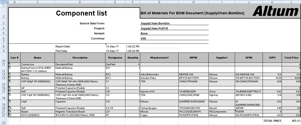
A common approach to BOM generation is to export the BOM data from Altium Designer, into a company-preferred Excel format spreadsheet. The BOM is generated from the Report Manager, which can be accessed from:
- ActiveBOM's Report menu
- The schematic and PCB editor's Report menu
- A BOM Report Output configured in an OutputJob
- Learn more about BOM Configuration in the Report Manager.
- For complete control over the BOM configuration process, including an interactive view of supply chain information as well as custom BOM rows and columns, add an ActiveBOM document (BomDoc) to your project. The BomDoc gives instant visibility into the component supply chain and also supports user-defined rows and columns, ideal for including those extra items, such as glue, labels, and so on. Creating and managing the BOM through a BomDoc is the recommended approach to BOM Management in Altium Designer.
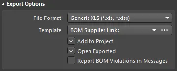
The Report Manager's Export Options includes two XLS File Format options:
MS-Excel (*.xls, *.xlsx) - requires Microsoft ExcelGeneric XLS (*.xls, *.xlsx) - uses a built-in XLS file generator, Microsoft Excel is not required

When an Excel option is selected a pre-defined Excel template can then be selected in the Template dropdown. When the Export button is clicked in the Report Manager the BOM data is generated and loaded into a new Excel Worksheet using the format defined in the chosen Excel template.
The list of templates available in the drop-down comes from:
- The Data Management - Templates page of the Preferences dialog
- For an unmanaged design, the default location is configured in the Data Management - Templates page of the Preferences dialog. Several example templates are included in the
\Templates folder of the installation user files.
- For a managed design, the available templates are stored in the
\Templates\BOM Templates folder of your managed content server.
How Design Data is Mapped in the Excel Template
Altium Designer data is mapped into the spreadsheet by including special Field and Column statements in the Excel template. The Field statement is used to map a single parameter, for example, a document parameter called Title. The Column statement is used to map per-component parameters, for example, the Designator component parameter.
Fields
The Field statement is used to map a document or project parameter, for example, the Title, into the BOM. The Field declaration is replaced by the passed value, as shown in the images below.
Fields are used in the format:
Field=<FieldName>
An example is Field=Currency
Fields should be defined above or below the Column region of the template.
Columns
Column declarations are used to map per-component parameters, for example, each component's Designator, Description, user-defined parameters, and so on. This can also include: line numbers, PCB location data, and custom column data entered into the BomDoc if there is a BomDoc in the project. The Column declaration in the template is replaced by the ColumnName string, with each row below being populated by that column value for each BOM Item, as shown in the two images below.
Columns are used in the format:
Column=<ColumnName>
An example is Column=Designator
Notes:
- Each column defined in the template must be displayed in the Report Manager for that column of data to be transferred. For example, in the images below, the
Line # column is displayed in the Report Manager, so can be included in the BOM (using the syntax Column=Line #). Note that the Line # column is only available as a user-configurable column when generating reports from an ActiveBOM BomDoc.
- The data will be presented in the Excel spreadsheet in the same row order as the Report Manager. Use the Report Manager's column sorting and sub-sorting feature to sort the rows as required.


- Example templates are included in the
\Templates folder of the installation user files.
- Available templates are configured in the Data Management - Templates page of the Preferences dialog.
- The default location for unmanaged (Local) templates is configured in the Local Templates folder field on that page in the Preferences dialog.
- For a managed design, the available (Server) templates are stored in the
\Templates\BOM Templates folder of your Altium Workspace (managed content server). These are only listed in the Preferences dialog when you are connected to a Workspace.
- The list of templates available in the Report Manager Template dropdown is based on the current configuration of templates in the Preferences dialog. Ensure that the Templates visibility option is configured to suit your needs.
- Excel templates support hiding rows or columns. This feature has been used in some of the example templates to hide the
Column = <ColumnName> declarations. To display hidden rows or columns in Excel, select all cells in the template, then right-click anywhere on the sheet and choose the Unhide command (show image).
Mapping Project-Level, BOM Header Information
Project-level information is typically mapped using the Field= statement, into the header of the BOM document.
Available System Fields
| Field |
Description |
| Currency |
The currency that has been chosen in the Supplier Options region of the Report Manager dialog. |
| DataSourceFileName |
The filename of the source used for the BOM data. |
| DataSourceFullPath |
The full path + filename of the source used for the BOM data. |
| GeneratorDescription |
For a BOM, this field displays Bill of Materials. |
| GeneratorName |
Name of the generator - BOM when output is generated by the Report Manager. |
| OutputName |
Title of the BOM, as displayed in the Report Manager (excluding the text "For BOM Document [<DataSourceFileName>]"). |
| OutputType |
For a BOM, this field displays BOM_PartType. |
| PCBDataSourceFileName |
The filename of the PCB data source. |
| ProductionQuantity |
Production quantity defined in the Report Manager dialog. |
| ProjectFileName |
Name of the PrjPcb file (including file extension). |
| ProjectFullPath |
Full path + the project filename. |
| ReportDate |
Date on which the report was created. |
| ReportDateTime |
Date and time at which the report was created. |
| ReportTime |
Time at which the report was created. |
| TotalQuantity |
Sum of the values in the BOM Items Quantity column. |
| Title |
Title displayed at the top of the BOM Reports dialog. |
| VariantName |
Name of the variant, as defined in the Variant Management dialog. |
| VersionControl_RevNumber |
Current revision of the BomDoc. |
| VersionControl_ProjFolderRevNumber |
Current revision of the project (incremented when a Commit Whole Project is performed). |
| <UserProjectParameter_n> |
Displays the value assigned to the user-defined UserProjectParameter-n. |
Mapping Document and Project Parameters
As well as the Field statements listed above, schematic Document Parameters (both default and user-defined parameters entered in the schematic document's Properties panel) and Project Parameters (Options for PCB Project dialog) can also be used as Fields, or as Columns.
Default Document Parameters
| Address1 |
Address2 |
Address3 |
| Address4 |
ApprovedBy |
Author |
| CheckedBy |
CompanyName |
ConfigurationParameters |
| CurrentDate |
CurrentTime |
Date |
| DocumentFullPathAndName |
DocumentName |
DocumentNumber |
| DrawnBy |
Engineer |
ImagePath |
| Index |
ModifiedDate |
Organization |
| Revision |
Rule |
SheetNumber |
| SheetTotal |
Time |
|
If the same parameter exists as both a document parameter and a project parameter, the project parameter takes precedence. If the same document parameter exists in multiple documents, the document parameter that is higher up in the hierarchy takes precedence.
Mapping BOM Item Information
The core region of a BOM is the grid of BOM Items, typically using a row for each component. Each column in this grid represents a component property, such as the designator, value, and so on. Columns are defined by entering the component property/parameter (BOM column heading), in the format:
Column=ColumnName
An example would be Column=Description, or Column=Designator
Column information can be taken from several sources, including:
Component Parameters
These ColumnNames are available for all components
| Comment |
ComponentKind |
Description |
| Designator |
DesignItemId |
Footprint |
| LibRef |
LogicalDesignator |
PartType |
| PhysicalPath |
Quantity |
UniqueIdName |
| UniqueIdPath |
<UserParameter_n> |
|
PCB Component Data
PCB component location information can also be included. In order to use these columns, the Include Parameters From PCB option must be enabled in the Report Manager dialog.
| Center-X(Mil) |
Center-Y(Mil) |
Center-X(mm) |
Center-Y(mm) |
| Pad-X(Mil) |
Pad-Y(Mil) |
Pad-X(mm) |
Pad-Y(mm) |
| Ref-X(Mil) |
Ref-Y(Mil) |
Ref-X(mm) |
Ref-Y(mm) |
| Layer |
Rotation |
|
|
Supplier Data
It is possible to retrieve online data from suppliers and include it in the BOM. Note that these are updated live, and are retrieved when the BOM is generated. Multiple suppliers can be set up for each component. In the table below, these have been described as Supplier Info x - replace x with the appropriate number.
| Manufacturer x |
Manufacturer Part Number x |
Supplier x |
| Supplier Currency x |
Supplier Order Qty x |
Supplier Part Number x |
| Supplier Stock x |
Supplier Subtotal x |
Supplier Unit Price x |
User-Defined Columns
User-defined columns are includes in the same way:
Column=ColumnName
