Parent page: Searching for & Placing Components
A component within a library represents the physical device that is placed on the actual printed circuit board. On a schematic sheet, a component is represented by its schematic symbol model. Each component can contain one or more parts.
Part
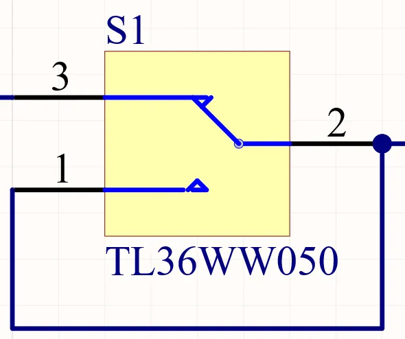
The Part represents the actual physical electronic component.
Summary
A Part is an electrical design primitive. It is a schematic symbol that represents an electronic device, such as a resistor, a switch, an operational amplifier, a voltage regulator, etc. Parts are stored within components in schematic component libraries. Note that each component can contain one or more parts. Along with a symbolic representation of the component, the part also includes links to models, such as the PCB footprint, and also parameters that are used to document details such as component parameters and supplier information. How the model links and parameters are added to the part depends on the type of library storage being used.
The terms Part and Component are both used to describe the symbol that represents the actual electronic device. The term Part is used because some components contain multiple parts. For example, a quad Op Amp component contains four separate Op Amps, or a resistor network can contain eight independent resistors. For these types of devices, you can create a separate schematic symbol to represent each Part during the component definition and place each of these parts independently. The terms Part and Component are used interchangeably on this page unless a multi-part component is being discussed.
Availability
Parts are available for placement in both the schematic and schematic library editors.
-
In the schematic editor, click Place » Part.
-
Right-click in the design space then choose Place » Part from the context menu.
-
From the Components panel, right-click on a component and select Place <ComponentName>.
-
From the Components panel, select a Generic Component as a placeholder.
-
Dragging and dropping a component from the Components panel.
-
Select the Place button in the Details pane of the Components panel, or by using the Enter hotkey.
-
From the SCH Library panel when in the schematic library editor, select a component, then click Place.
Placement from the Components Panel
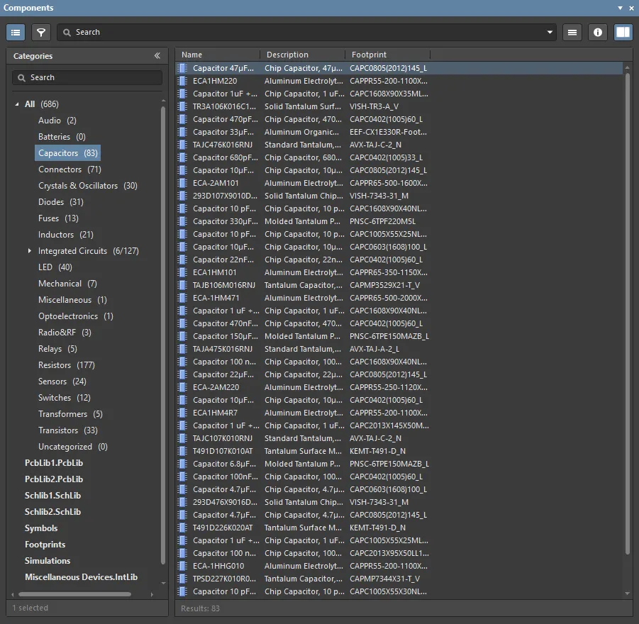
In the schematic editor, the part selection and placement process may be done from the Components panel.
-
The panel displays the contents of the currently selected library. Use the drop-down next to the library name to choose another library.
-
Use the mask field below the currently selected library field to filter the list and speed the searching process or scroll and select the required part.
-
Click Place, double-click, or click and drag to place the selected component onto the active schematic sheet. While the part is floating on the cursor, it can be rotated (press Spacebar), mirrored along an axis (press X or Y), or edited (press Tab) before placement.
-
The columns shown in the list of components in the currently selected library can be reorganized (click and drag) or reconfigured (right-click, then choose Select Columns).
-
Click the
 button within a Generic Component tile to attach the component to the cursor for placement in the active Schematic document. Selecting the tile itself will open that component type category in the Components panel.
Searching for a Component
The non-Workspace library menu options provide you the ability to set preferences, perform searches, and migrate database and file-based library content. To access these options, select the library menu  button at the top right of the Components panel.
Select File-based Libraries Preferences to open the Available File-based Libraries dialog, where you may view controls to add or remove libraries, install libraries, and specify library search paths.
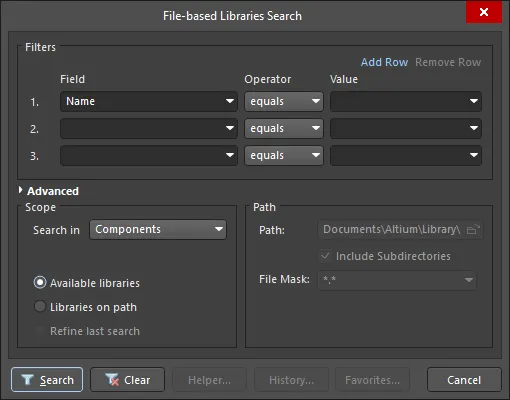
The current listing of database and file-based library components may be filtered by entering a search phase in the Components panel Search field. To access more advanced search capabilities for component libraries, select the File-based Libraries Search option from the panel’s  menu (top right), which opens the File-based Libraries Search dialog. The dialog offers flexible search options including query-based filter constraints, and the ability to search through all available database and file-based libraries or those within a specified path.
-
The default search Scope is to search for Components in the Available File-based Libraries.
-
Alternatively, the dialog also supports searching through Libraries on path stored in folders on a drive. To do this, enable the Libraries on path option then configure the Path options as required.
-
The Filters use "AND" and, therefore, it is better to start with a simple filter and if there are many results, use the Refine last search mode to search within the results.
-
Query search results are presented in the File-based Libraries Search dialog when selecting Helper.
Placing from the Schematic Library Editor
A Part also can be placed directly from a library that is open in the schematic library editor from the SCH Library panel. Note that:
Graphical Editing
Graphical editing for a part is limited to moving, rotating, and mirroring. When a part is selected in the design space, a dashed selection box will appear around it. To graphically manipulate a selected component:
-
Press Delete to remove the selected part from the design.
-
Click and hold to move the selected part. The cursor will jump to the nearest electrical hotspot (the wiring end of the nearest pin).
-
Press the Spacebar to rotate the arc counterclockwise or Shift+Spacebar for clockwise rotation. The action can also be performed while dragging the object. Rotation is in increments of 90°.
-
While a part is moving on the cursor, press the X or Y key to mirror it along that axis.
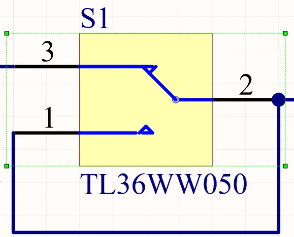
A selected Part
When a component is rotated, its text strings are automatically repositioned to suit the new orientation. This behavior can be disabled if required. To do this, edit the string then clear the
Autoposition checkbox in the Parameters Properties panel. Note that manually positioned text strings are denoted by a dot. These dots can be hidden if required by clearing the
Mark Manual Parameters option on the
Schematic – Graphical Editing page of the
Preferences dialog.
Working Between the Schematic Component and the PCB Component
The software includes tools to help work between the component on the schematic and that same component on the PCB. These tools include Cross Probing, Cross Selection, and Selecting the PCB Components from the schematic.
Cross Probe
As the name implies, Cross Probe allows you to click on a component in one editor and jump to that component in the other editor. To Cross Probe:
-
Click Cross Probe located on the schematic or PCB editor menu on the Tools menu.
-
When you click the component in the schematic editor, it will be centered and zoomed in the PCB editor. The zoom level is set on the System – Navigation page of the Preferences dialog.
-
The default behavior is to remain in the same editor, ready to cross probe another component. To switch to the other editor as you Cross Probe, hold the Ctrl key.
Cross Select Mode
Cross Select Mode selects the same component in the other editor. Note that it does not zoom and center. Cross Selection is either on or off. Click Tools » Cross Select Mode to toggle the mode on/off. Select multiple components by holding the Shift key as you click to select.
Selecting the PCB Components
This feature allows you to select multiple schematic components in a specific order, then place those same components in the PCB editor in the same order. To use this feature:
-
Select the components on the schematic one by one (hold Shift as you click to select multiple components).
-
Switch to the PCB editor then press the I, C shortcut to launch the Reposition Selected Components command. The Reposition Selected Components command is also available on the right-click menu after pressing the I shortcut.
Part Properties

General Tab
General
-
Reuse Block – when the component is a part of a reuse block, this field shows the name of the parent reuse block. Click the Reuse Block hyperlink to see the properties of this reuse block.
-
Designator – enter the designator. Toggle the eye icon to show/hide the designator. Use the lock icon to lock/unlock the designator.
-
Comment – enter the name. Toggle the eye icon to show/hide the name. Use the lock icon to lock/unlock the name.
-
Part <x> of Parts – displays the number of the selected part and the total number of parts. Use the drop-down to select the number of the associated part then enter the total number of parts. Click
 to lock/unlock the fields.
-
Description – the component/part description.
-
Type – select one of the following component types for the component footprint here. The available types are:
-
Standard – components that possess standard electrical properties, are always synchronized between the schematic and PCB (the footprint, pins/pads, and net assignments must all match), and are included in the BOM. An example is a standard electrical component, such as a resistor.
-
Mechanical – components that do not have electrical properties, are not synchronized (you must manually place them in both editors), and are included in the BOM. An example is a heatsink.
-
Graphical – components that do not have electrical properties are not synchronized (you must manually place them in both editors), and are not included in the BOM. An example is a company logo.
-
Net Tie (In BOM) – components that are used to short two or more different nets together, are always synchronized between the schematic and PCB (the footprint, pins/pads, and net assignments must all match), and are included in the BOM. They differ from a Standard component in that connectivity created by copper within the footprint is not checked; it is this copper that allows the nets to be shorted. Note: enable the Verify Shorting Copper option in the Design Rule Checker dialog to verify that there is no unconnected copper within the component.
-
Net Tie (No BOM) – components that are used to short two or more different nets together, are always synchronized between the schematic and PCB (the footprint, pins/pads, and net assignments must all match), and are not included in the BOM. They differ from a Standard component in that connectivity created by copper within the footprint is not checked; it is this copper that allows the nets to be shorted. Note: enable the Verify Shorting Copper option in the Design Rule Checker dialog to verify that there is no unconnected copper in the component.
-
Standard (No BOM) – components that possess standard electrical properties, are always synchronized between the schematic and PCB (the footprint, pins/pads, and net assignments must all match), and are not included in the BOM. An example is a testpoint component that you want to exclude from the BOM.
-
Jumper – components that are used to include wire links in a PCB design, for example, on a single-sided PCB that cannot be fully routed on one layer. For this component type, the component footprint and pins are synchronized between the schematic and PCB but the net assignments are not, and the component is included in the BOM. As well as selecting this option at the component level, both of the pads in the component must have their JumperID set to the same non-zero value. Jumper type components do not need to be wired on the schematic; they only need to be included on the schematic if they are required in the BOM. If they are not required in the BOM, they can be placed directly in the PCB where the Component Type is set, the JumperIDs are set, and the Nets manually assigned for the pads.
-
Design Item ID – this field lists the name of the component selected (for a Workspace component), the chosen key field defined in the Field Settings region of the DbLib/SVNDbLib file (for a database library component), or the Design Item ID parameter defined for the component symbol (for a file-based library component). Click
 to open the Replace Component dialog. This dialog grants access to full details of the selected component (Parameters, Models, Part Choices, Supplier data, etc.), component comparison, and the ability to replace the current component with another, among other possibilities. If another component is selected as a replacement, this field will then display the full Design Item ID for the newly selected component. Click the Validate button (
 ) to display information regarding where the component resides. If it is a non-Workspace component, the file path in which it is saved on your computer will appear. If it is a Workspace component, the information will indicate that the component was simply found.
-
Source – displays the name of the source library of the component. Click
 to search for and select the desired library.
-
Revision state – this field displays the current lifecycle state of the selected component revision, with the color icon and name of the revision state.
If a component used in a design (or managed schematic sheet) has been deleted, this will be indicated at the bottom of the
General tab in the
Properties panel by the associated

icon.
-
Revision status – if the selected component revision is in an applicable state (allowed for use in designs) the entry will either reflect that the revision is the latest (Up to date) or not (Out of date). If the revision is in an inapplicable state (not allowed for use in designs) the entry will display Not applicable. Click the  button to update the component to the latest revision.
When clicking the

button and not all parts of an out-of-date multipart component are selected, you will be prompted to update all parts of this component. Click
Yes in the
Confirm dialog that opens to continue.
-
Component issues (Properties panel only) – if a selected component sourced from the connected Altium 365 Workspace has any health issues, an indication of this will be presented by the  (for errors) or
  (for fatal errors) icon. The number at the right of the icon indicates the number of found issues. Click the down arrow at the right of the number to see the short descriptions of the issues.
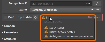
An example of library health issues found.
-
Your Workspace library health can be explored in more detail through the Library Health dashboard page accessible from the Altium 365 Workspace browser interface. Learn more about Library Health Dashboard.
-
Note that the selected component's Properties panel reflects the current state of the Library Health reports. These reports are updated automatically within a day in response to a changed component part. You can also update the reports manually. Learn more about Refreshing the Dashboard.
-
Supply Chain Data (Properties panel only) – this field displays the supply chain information from related Part Choice:
-
Median unit price. This entry will be displayed in red text if there are no prices, or the price = 0.
-
Stock. This entry displays the total sum of the stock available from the suppliers enabled as part of the Altium Parts Provider source for your Workspace.
-
Manufacturer Lifecycle Bar. Hover over the bar for an informative tool-tip. This can appear in one of four states:
-
White/Gray = Default, unknown or no information
-
Green = New or Volume Production states
-
Orange = Not Recommended for New Design
-
Red = Obsolete or EOL
The manufaturer lifecycle status is designed to be used as an indicator, for a number of reasons:
-
Altium maintains a database of many millions of components, produced by thousands of component manufacturers. Since there is no single, consistent method used by those manufacturers to reflect a component's lifecycle state, the status is based on information aggregated from manufacturers, global distributors and global sales analysis.
-
A part is only reported as EOL or Obsolete when there is at least one authorized distributor or manufacturer that has confirmed this status.
-
Determining the Not Recommended for New Design status is more complex. Manufacturers sometimes just report if a part is active or not, and may not give advance warning that a part is to be discontinued or replaced. Therefore this lifecycle status does not always concur with the status provided by the manufacturer. The status algorithm uses various information, including real time and historical stock availability from all distributors, to try to determine the availability of the part. Parts which have consistently poor availability (when they have been generally available in the past), or cannot be sourced over a period of time after having previously having good availability, will eventually be flagged as Not Recommended for New Design (if they are not already EOL or Obsolete).
-
The idea of the lifecycle status indicator is to provide simple-to-understand information that helps you to make more informed decisions about a part, by highlighting those parts which may be problematic. However, due to the sheer volume of data and number of components that are managed, there is always a chance that the Altium status lags behind the instantaneous manufacturer status, and is therefore not up-to-date. It is not possible for Altium to guarantee the accuracy of the lifecycle status, it is recommended that if there is any doubt that you double-check with the manufacturer for authorized lifecycle information.
Location
-
(X/Y)
-
X (first field) – the current X (horizontal) coordinate of the reference point of the object, relative to the current design space origin. Edit to change the X position of the object. The value can be entered in either metric or imperial; include the units when entering a value whose units are not the current default.
-
Y (second field) – The current Y (vertical) coordinate of the reference point of the object, relative to the current origin. Edit to change the Y position of the object. The value can be entered in either metric or imperial; include the units when entering a value whose units are not the current default.
-
Rotation – use the drop-down to select the rotation. Choices are
0 Degrees, 90 Degrees, 180 Degrees, and 270 Degrees.
Parameters
-
Grid – lists the Name and Value of the parameters associated with the currently selected component. Use
 to lock/unlock a listed parameter and prevent it from being updated. Parameter values can be manually entered, or selected from a drop-down menu list that offers values sourced from all the available components of that type. You may toggle the eye icon to show/hide the parameter.
-
Favorites – parameters marked as Favorites will be shown in the Parameters list, while those not marked will be hidden. Hover to the right of a parameter filter’s name and click the  icon to set the filter as a Favorite. To remove a parameter as a Favorite, click the icon again.
To see all hidden parameters, click the Show More link at the bottom of the list. Click the Show Less link to view Favorite parameters only.
This feature is available by enabling the
Schematic.UI.ShowMoreOrLessParameters option in the
Advanced Settings dialog. When this option is disabled, the Favorite parameters and the
Show More/Show Less features are disabled, resulting in all of the component parameters always being displayed in the
Component mode of the
Properties panel. Note that displaying all parameters may affect software performance.
-
Font – click on the displayed font to change the font style.
-
Other – click to open a drop-down to change additional options:
-
Show Parameter Name – enable to show the parameter name.
-
Allow Synchronization with Database – enable to synchronize with the database. This option is used to control if the comment can be updated. By default, these options are enabled to always allow synchronization with the source library/database. You may disable this option to prevent that comment from being included in an update process.
-
(X/Y) – enter the X and Y coordinates.
-
Rotation – use the drop-down to select the rotation. Choices are:
0°, 90°, 180°, and 270°.
-
Autoposition – check to enable auto-positioning, meaning that the parameter is positioned automatically every time the associated component is rotated. Disable this option to keep the parameter position to the associated component when it is rotated.
-
Add – click to add a parameter, such as a footprint, model, or rule, among others. Click
 to delete a selected entry from the grid. Click
  to edit the parameter via the parameter's respective dialog.
Graphical
-
Mode – use the drop-down to select the desired mode. If no modes other than Normal are available, this drop-down will be grayed out.
-
Mirrored – enable to mirror the part.
-
Local Colors – enable the local color option and the schematic component's fill, line, and pin colors are overridden with the colors from the Fill, Lines, and Pins color boxes respectively. Disable this option to use the predefined colors from the library.
Part Choices
This region provides information about part choices and supplier links assigned to the selected component. Refer to the Adding Supply Chain Information to a Component page to learn more about information provided by entries in this section.
If no part choices are available, a button that will open the
Edit Supplier Links dialog will be made available, which you may use to add supplier links for a component.
Pins Tab
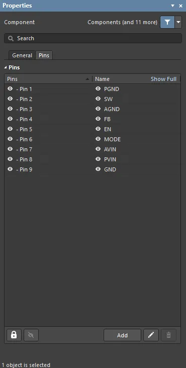
-
Grid – this region lists the Pins and Names for all the pins of the selected component. Use the eye icon to show/hide the pin. Use the lock icon to lock/unlock the pins.
For a multi-functional pin (a pin that has functions specified in the Functions filed in the Pins mode of the Properties panel), click in the pin's cell in the Name column and select the pin function in the drop-down that appears. The selected function will be shown as the pin name on the schematic sheet.
Note that you can not only select a pin function from the drop-down but also manually enter a new pin name in the Name column of that pin. If the entered pin name differs from the pin name and functions defined for that pin, this name will be considered temporary and highlighted in yellow in the grid.
Display of pin names on schematic symbols can be managed by clicking on the name of a pin with custom names defined. In the pop-up window that opens, check the function names you would like to display on the schematic symbol. If no custom pin name is selected in the list, the default name will be shown.
Note that the names of pins with custom names use a background color different from the component body color to distinguish such pins in the design space (this will not affect the schematic printouts).
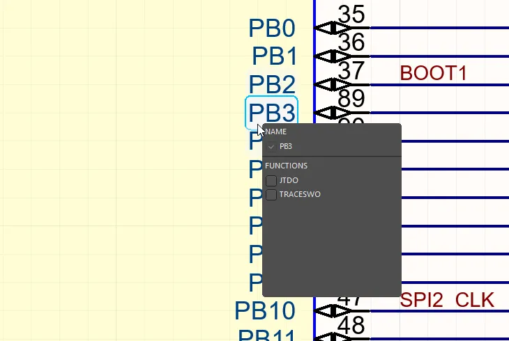
Example of a pop-up menu for a pin with custom pin names. Hover the cursor over the image to see this pin after selecting some custom names.
When a component placed on a schematic sheet is being updated from its source library, and pins of the component have custom naming defined on the schematic sheet only, updating will not remove the custom pin naming.
-
Show Full/Show Short - in Show Full the full extended pin names of all listed pins are displayed; in Show Short mode, the current pin name is displayed.
-
 – when the button is enabled (the closed lock icon), the pins of the component are prevented from being edited. Only the component itself can be edited. If you wish to edit a pin by selecting it in the design space, disable this option.
-
 – use this button to toggle the visibility of the component's pin on the schematic sheet.
-
Add – click to add a pin. Click
 to delete a selected entry from the table. Click
  to open the Component Pin Editor dialog in which you can view all pins for either the component in the active schematic library document or a placed component (or part thereof) in the schematic editor.
Generic Component Properties
Generic Components
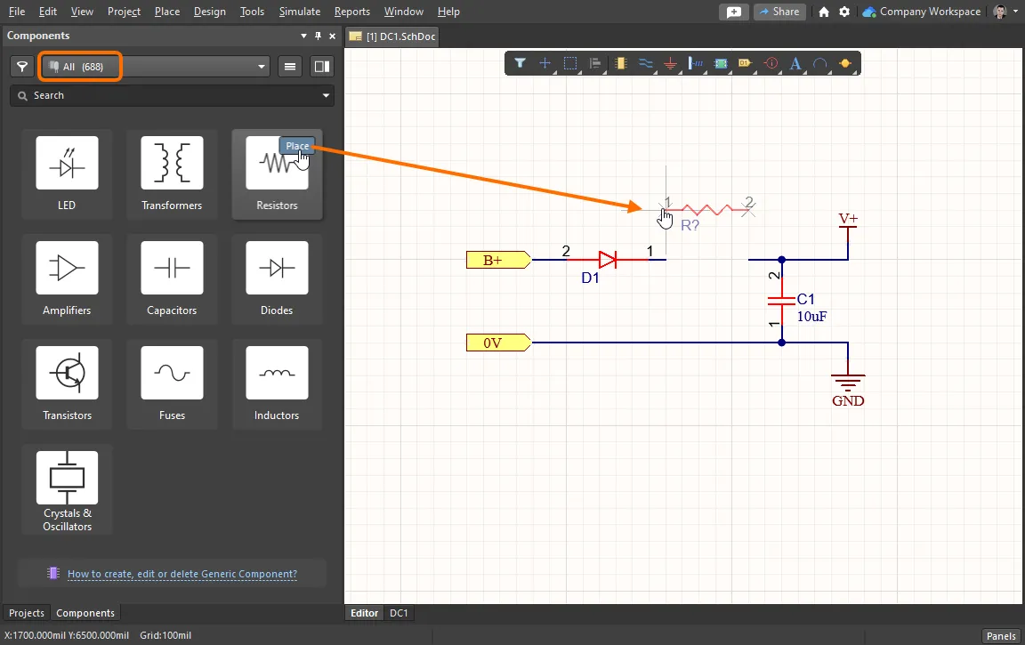
Placing a Generic Component from the Components panel
When Altium Designer is connected to a Workspace, the available Generic Components can be accessed from the Components panel where they are exposed when the All option is selected in the Categories pane – or from the top drop-down menu when the panel is in its compact mode. Click on the  button within a Generic Component tile to attach the component to the cursor for placement in the active schematic. Selecting the tile itself will open that component type category in the Components panel.
Generic Component Properties

General
-
Designator – enter the designator. Toggle the eye icon to show/hide the designator. Click the lock icon to lock/unlock the designator.
-
Comment – enter the name. Toggle the eye icon to show/hide the name.
-
Description – the generic component/part description.
-
Replace – select the Replace button when a design has progressed to the point where a Generic Component can be replaced with a specific physical component using the Replace Component dialog.
Location
-
(X/Y)
-
X (first field) – the current X (horizontal) coordinate of the reference point of the object, relative to the current design space origin. Edit to change the X position of the object. The value can be entered in either metric or imperial; include the units when entering a value whose units are not the current default.
-
Y (second field) – The current Y (vertical) coordinate of the reference point of the object, relative to the current origin. Edit to change the Y position of the object. The value can be entered in either metric or imperial; include the units when entering a value whose units are not the current default.
-
Rotation – use the drop-down to select the rotation.
Parameters
-
Grid – lists the Name and Value of the parameters associated with the currently selected component. Use the lock icon to lock/unlock a listed parameter. Parameter values can be manually entered, or selected from a drop-down menu list that offers values sourced from all the available components of that type. You may the eye icon to show/hide the parameter.
-
Font – click on the displayed font to change the font style.
-
Other – click to open a drop-down to change additional options:
-
Show Parameter Name – enable to show the parameter name.
-
Allow Synchronization with Database – enable to synchronize with the database. This option is used to control if the comment can be updated. By default, these options are enabled to always allow synchronization with the source library/database. You may disable this option to prevent that comment from being included in an update process.
-
(X/Y) – enter the X and Y coordinates.
-
Rotation – use the drop-down to select the rotation.
-
Autoposition – check to enable auto-positioning, meaning that the parameter is positioned automatically every time the associated component is rotated. Disable this option to keep the parameter position to the associated component when it is rotated.
Designator
 The Designator uniquely identifies each component in the design.
Summary
The designator field is a child parameter object of a schematic component (part). It is used to uniquely identify each placed part to distinguish it from all other parts placed in all the schematic sheets in the project.
Availability and Placement
The designator is automatically placed when the parent component part object is placed. It is not a design object that you can directly place.
Graphical Editing
The designator string can be edited graphically using what is known as in-place editing. To edit a designator string in place, select the designator by dragging your cursor around it, then hit enter.
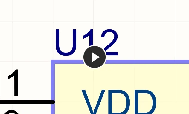
An example of in-place editing
Once editing is complete, press Enter or click away from the string to exit in-place editing mode.
Non-Graphical Editing
There are two aspects to consider in relation to editing the designator: editing the value of the designator and editing the display properties of the designator.
Rather than manually editing each component designator, it is more practical to leave the assignment of the designators until the schematic is complete. After that, all designators can be logically assigned for the entire project using one of the Schematic Editor Annotate commands (Tools » Annotation) which offer full control for sheet-by-sheet positional annotation. For more information about annotation, see Annotating the Components.
The designator (and comment) strings can be displayed in the schematic library editor then doubled-clicked on to edit the properties. The  icon associated with the field in the Properties panel is used to show or hide the designator.
Editing the Designator Value in the Schematic Editor
The designator can be defined in the schematic editor as the component is being placed or after the component has been placed on a schematic sheet in the Properties panel.
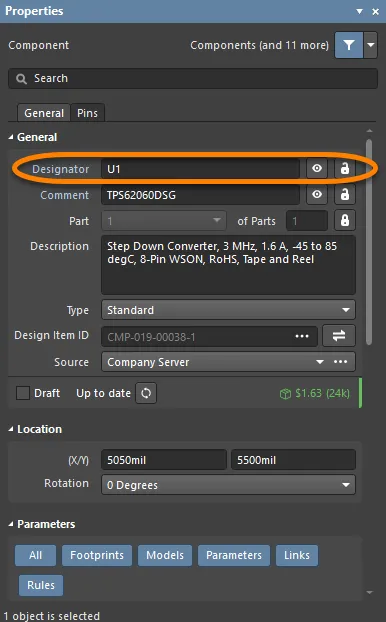
-
To edit the designator during component placement, press the Tab key while the component is floating on the cursor. The Properties panel will open; enter the required designator string. Click the design space pause button overlay (
 ) to resume placement.
-
Continue to place components or press Esc to terminate placement.
-
Press the Spacebar to rotate the arc counterclockwise or Shift+Spacebar for clockwise rotation. The action can also be performed while dragging the object. Rotation is in increments of 90°.
-
To edit the designator after placement, double-click on the placed component to open the Properties panel where the designator can be edited.
Editing the Designator Display Properties
The appearance of the designator string, which includes the font type, size, and color, can be configured on the Schematic - Defaults page of the Preferences dialog. These settings will apply unless overridden by settings defined in the component symbol in the Schematic Library Editor.
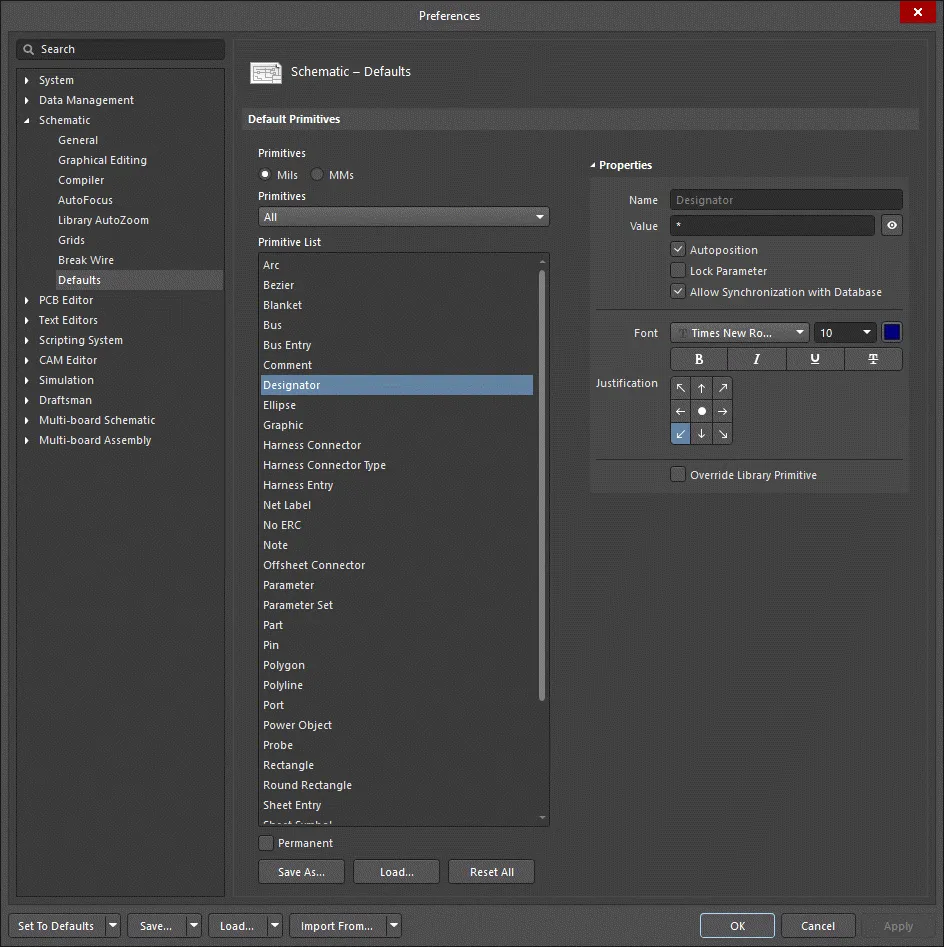
Fixing the Location of the Designator String
The default behavior of the Designator is to auto-position it as a component is rotated during placement. If this behavior is not required, turn off the Autoposition option in the Preferences dialog (refer to the previous image) either during symbol creation or after the component has been placed on a schematic sheet. Note that doing this sets this parameter to be classified as a manual parameter (meaning manually positioned parameter). Manual parameters are identified by a dot on the lower left corner of their selection box.
Control the display of manual parameter marker dots using the
Mark Manual Parameters option on the
Schematic - Graphical Editing page of the
Preferences dialog.
Notes
-
The Schematic Editor includes a simple auto-increment feature for the designator that can be used during the placement of multiple instances of the same part. To use this, press Tab while the first component is floating on the cursor and enter a suitable designator, for example
R1. Subsequent components will then be designated R2, R3, etc. Note that when you switch to placing a different component type you must again press Tab and enter a suitable designator prefix.
-
When placing multi-part components and the initial designator is assigned as just described, a part suffix will automatically be assigned, for example,
U3A, U3B, etc. If the initial designator is not assigned, all parts will have the same suffix. This is resolved by the Schematic Editor's Annotation command. The part suffix can be alpha or numeric. Use the Alpha Numeric Suffix option on the Schematic - General page of the Preferences dialog to configure.
Designator Properties
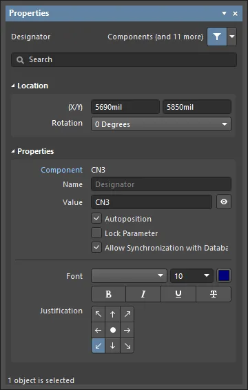
Location
-
(X/Y)
-
X (first field) - the current X (horizontal) coordinate of the reference point of the object, relative to the current workspace origin. Edit to change the X position of the object. The value can be entered in either metric or imperial; include the units when entering a value whose units are not the current default.
-
Y (second field) - The current Y (vertical) coordinate of the reference point of the object, relative to the current origin. Edit to change the Y position of the object. The value can be entered in either metric or imperial; include the units when entering a value whose units are not the current default.
-
Rotation - use the drop-down to select the rotation.
Properties
-
Object - displays the associated object.
-
Name - enable this field by clicking the visibility icon (
 ) to add the prefix "Designator:" to the designator value itself. Doing so visually distinguishes and confirms that the text value is a designator within the schematic document.
-
Value - displays the designator name itself. Toggle the eye icon
 to show/hide the value.
-
Autoposition - check to enable auto-positioning, meaning that the text will remain in the chosen position as the component is moved and rotated.
-
Lock Parameter - check to lock the parameter, which prevents the value from being edited from the Properties panel or schematic document.
-
Allow Synchronization with Database - enable to synchronize with the database. This option is used to control if the comment can be updated. By default, these options are enabled to always allow synchronization with the source library/database. You may disable this option to prevent that comment from being included in an update process.
-
Font - use the controls to select the font, font size, font color, and add any desired special characteristics to the font, such as bold, italics, and underlines.
-
Justification - click the arrows to configure the justification of the text or circle to center.
-
Override Library Primitive (Preferences dialog only) - enable this checkbox to override the primitive settings defined for the designator object in a library. Therefore, when a component is placed, it will adopt the primitive settings you have defined in the Preferences dialog, rather than those that have been defined for the component in the library.
Updating and Replacing Components from a Library
Having initially placed components onto schematic sheets of a board design, there now needs to be some way of updating those component instances, with any changes to their linked source components in the applicable Workspace. In other words, a means by which to keep the design synchronized with the Workspace entities that it uses.
For example, a component may have been re-saved to the Workspace, perhaps reflecting a change to a child model. This results in a new revision of that component. The placed instance of that component is now using an older revision and you may want to update it to use the latest revision instead. Alternatively, you may have decided to use a different component altogether, and simply need to change the existing component in the design for an alternate one.
There are various methods available by which to manage the components after initial placement into a design.
Single Instance Component Change
Each placed component has a link back to the component revision in the Workspace. This information can be found on the Properties panel, when browsing the properties for the selected component.
 Each placed instance of a component has a link back to the specific revision of that component in the Workspace.
If there is a later revision of the existing component available, the entry for the revision status (on the
Properties panel) will reflect this using the text
Out of date, to the right of the current revision's lifecycle state. Note that if the lifecycle state has been marked as not being allowed for design (
Allowed to be used in designs option disabled for it in the
State Properties dialog), then the entry will instead show as
Inapplicable.
At this lowest, individual component level, the placed instance can be:
-
Updated to the latest revision of the existing component, by clicking the
 button.
 Example of updating the same component to its latest revision – hover over the image to see the result.
-
Switched out for the latest revision of a different (a replacement) Workspace component or a file-based library component by clicking the  button at the right of the Design Item ID field. The Replace Component dialog will open, presenting components in your connected Workspace and available file-based libraries. The current component is shown at the top of the list. Search for the replacement component required, select it, then click OK.
 Example of replacing the existing component with a different one (an alternate)
The Replace Component dialog provides direct access to all available Workspace library components and file-based library components. The dialog offers full details of the selected component (Parameters, Models, Part Choices, Supplier data, etc.,), component comparison, and for Workspace Library Components, a filter-based parametric search capability for specifying target component parameters.
The Replace Component dialog can also be accessed from other places of Altium Designer when performing a component replacement operation, e.g. from an ActiveBOM document or the Item Manager dialog.
Options and Controls of the Replace Component Dialog
-
Search - use the search text box to manually search for a specific component.
-
 - click to expand or collapse the Categories pane - to show certain types of components, or to display all available components. Use the search bar underneath the Categories pane to manually search for a specific component category or available file-based component library.
-
 - click to access a menu and select from:
-
 - click to open/close the Details region of the dialog (described below).
Filters
When a category of Workspace components is selected, click the Filters icon ( ) to open the Filters region, where you can further filter the categories that are selected in the Components list. The panel Filters options can be tailored your needs by selecting particular parameter types as Favorites, which then shift to the top of the list for the current component Category. Hover to the right of a parameter filter’s name and click the (
 ) icon to set the filter as a Favorite. Favorite filter settings apply to and are saved for individual component Categories.
Components
-
Name - the name of the component.
-
Description - the description of each component.
-
Footprint - the footprint of the component.
-
Results - lists the total number of components found/listed in the search.
Details
Click

to display the
Details region for the selected component.
-
Component Revision ID - lists the Revision ID and price of a given component. Click the Revision ID to open the Explorer panel for further information regarding a component.
-
References - click to open reference information in a web browser for the component. Use the drop-down to access the Manufacturer URL or Datasheet.
-
Place - click to place the selected component on a schematic document.
-
Component information - lists relevant information about the component, including manufacturer, release date, and descriptive information. Click the Show More link to view all information; click Show Less to collapse the information.
-
Models - expand to view the provided models. Use the available links to display various parts of a single model.
-
References - expand to access the Manufacturer URL, Datasheet, and Package Specification.
-
Part Choices - expand to view the part choices. A name, price, and description is provided. The Datasheet of the component also will be listed.
-
Where Used - expand to view the projects that utilize the component.
Right-Click Menu
-
Find Similar Components - click to open the Find Similar Components dialog, where you may search for several other components with similar characteristics.
-
Place <component> - click to place the component in the appropriate document.
-
Edit - click to open the selected component's Component Library Documents.
-
Navigate to <revision> - click to open the selected component within the Explorer panel.
-
Operations - hover to access the ability to Submit Request, Create, Download, Clone, Change Component Type, Create / Edit PCL, and Full Item History.
-
Refresh- click to refresh to view recent updates or edits. You may also refresh by using the F5 shortcut.
-
Library Report - when a file-based library is selected in the Categories pane, click to access the Library Report Settings dialog, in which you can use the provided co ntrols to configure a library report.
Effecting Batch Component Changes – the Item Manager
Related page: Managing Content with the Item Manager
Individual component change is great, however, it soon becomes tiresome when dealing with a more sizable number of components. For this, you need a single, centralized place from which to effect multiple changes in a batch-like manner. Enter the Item Manager (Tools » Item Manager).
The Item Manager is 'command-central' for synchronizing Workspace design entities – placed on schematic sheets – with the source content they are linked to in a Workspace. It automatically detects and lists all components, flagging if they are Workspace entities or not, and then compares the Item-Revision of each Workspace component on the schematics against the available revisions of that component in the Workspace. For each entity, information about the current linked Item is given, in terms of revision, lifecycle state, and the source Workspace in which it resides.
The automated comparison of revisions for Workspace content flags any that is out of date. That can then be selected and prepared for update to the latest revision with minimal effort. For more detail, see
Detecting when Updates are Required.
You have full control over which of these Workspace entities to update, and how. For example:
-
Select an individual entry and update it to use the latest revision of the linked Item, or choose to use the latest revision of a completely different Item.
-
Select a group of entries that utilize the same linked Item and either update them to the latest revision of that Item, or choose to use the latest revision of a completely different Item.
All proposed changes are reflected in the manager.
Once changes have been set up as required, generate an Engineering Change Order (ECO) and browse the actions that will be taken to implement those changes. Disable any actions if required – you are always in the driving seat! When ready, execute the ECO and the changes will be affected. Fast and efficient, your placed Workspace content is managed with simplistic ease.
If you're confident in the changes you are making, you can use the Item Manager's Apply ECO feature – effecting the changes quietly, without popping the Engineering Change Order dialog.
The following examples illustrate use of the Item Manager:
-
To update multiple components to use the latest revision of the existing Workspace component.
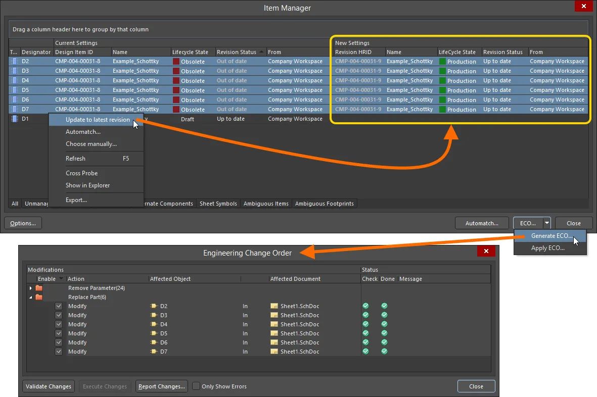
Update a group of out-of-date components to their latest revisions.
-
To change a couple of components for the latest revision of a different Workspace component – chosen through the Replace Component dialog.
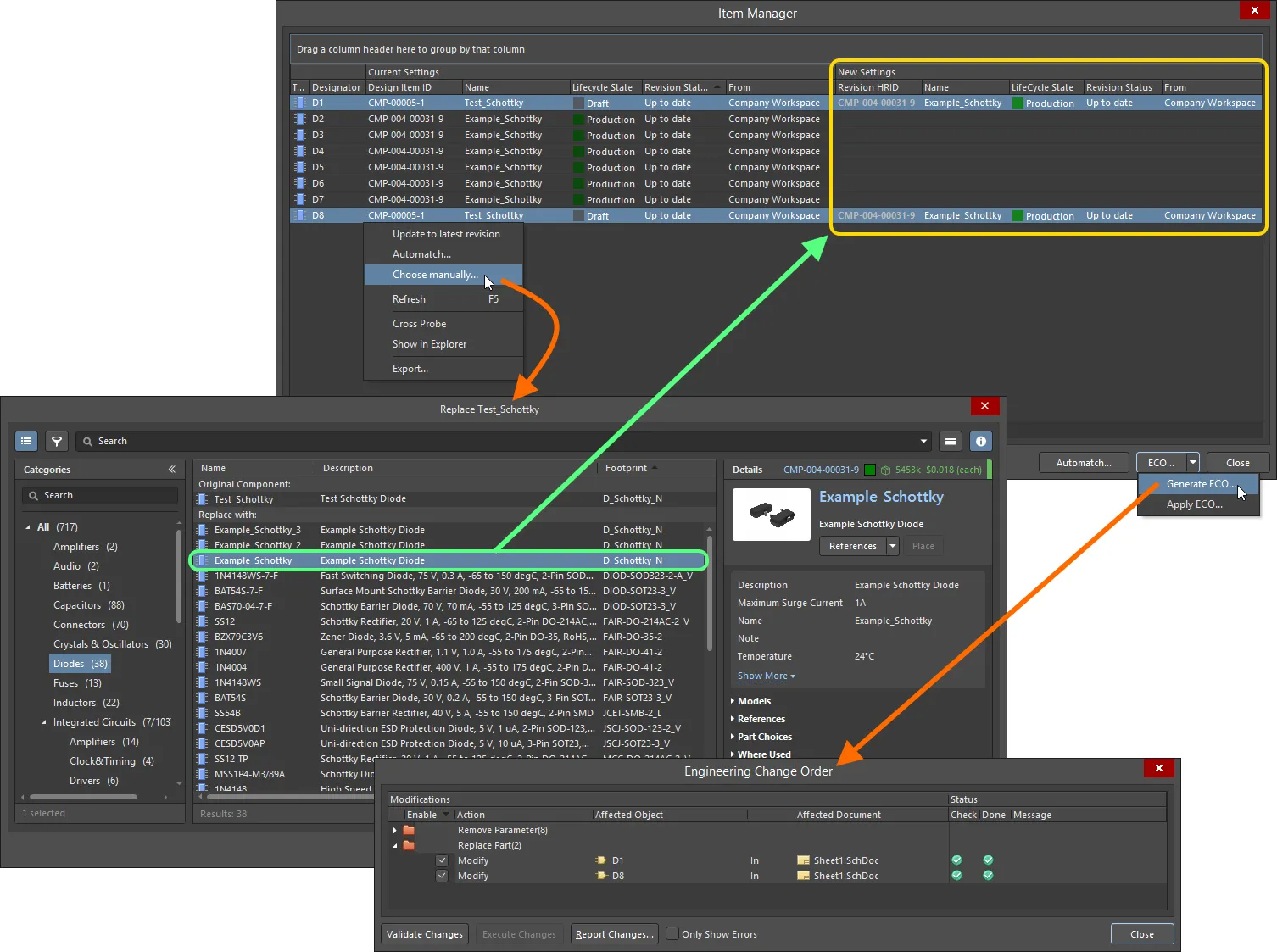
Replace one or more components with a different Workspace component.
Not only can the Item Manager be used to keep your components in your designs in sync with changes to the source content in the connected Workspace(s), it is also a powerful tool to aid in the migration of your existing board designs – from using local design items to using Workspace design content. Once you have migrated your design components to a Workspace, and any schematic sheets (device sheets), you use the Item Manager to 'replace' the existing components and sheet symbols with their newly migrated Workspace incarnations. In other words, the components remain the same, from the design perspective, but the source of those components changes.
Powerful auto-matching capabilities enable you to quickly match local components and sheet symbols to Items in the Workspace.
Changing a Component from a BomDoc
It's not uncommon to identify an issue with a component when the BomDoc is being checked and made ready for ordering the parts. For example, the designer may have forgotten to finalize the selection of a component, or a component has gone EOL and the designer wants to explore the price and availability of potential replacements. While you could resolve this by returning to the schematic and editing the component, selecting a suitable part, then refreshing the BomDoc, ActiveBOM supports performing this directly from within the BomDoc – then pushing that change back to the schematic via an Engineering Change Order.
From within the BomDoc, right-click on the selected component(s) and select the Operations » Change <ComponentName> command. The Replace Component dialog will open, from where the replacement component can be searched for. After finding the desired replacement component select it, then click OK. The Engineering Change Order dialog will open, detailing the changes needed to synchronize the schematic with the BomDoc.
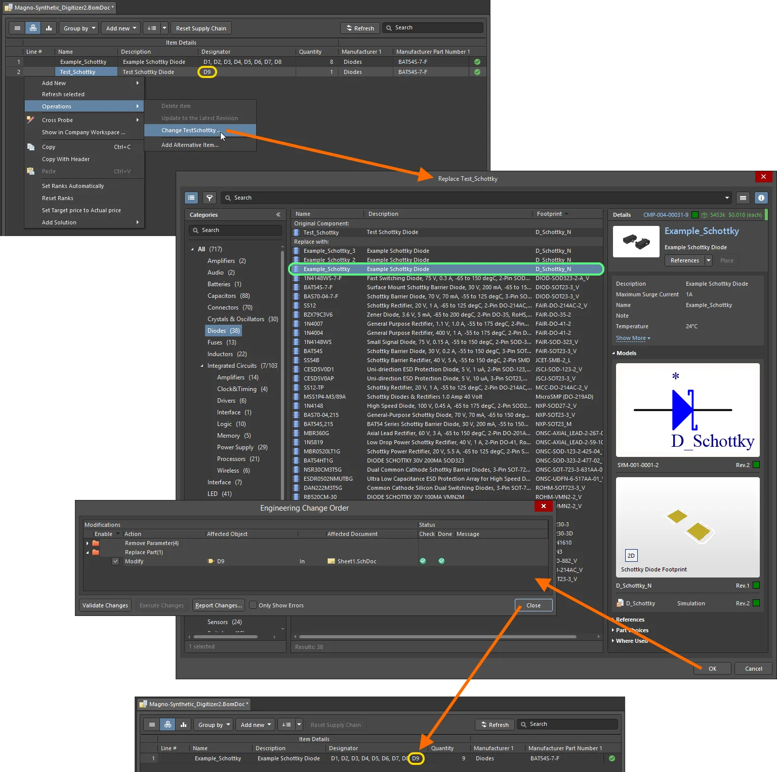
Example of component replacement directly from within a BomDoc.
-
The replace component feature searches for a new component in the currently active Workspace.
-
If the component change also affects the board design, an update to the PCB should also be performed from the schematic.
-
The Replace Component dialog has a similar layout and shares many of the features with the Components panel.
Replacing a Generic Component
When a design has progressed to the point where a Generic Component can be replaced with a specific physical component, invoke the Replace Component dialog by selecting the  button in the Properties panel. Note this also can be done from the Item Manager or through the project's ActiveBOM document.
Parameter values that have been applied to the Generic Component (here, power and resistance values) are automatically used as search terms in the Replace Generic Component dialog, allowing you to choose a suitable replacement component from the filtered results – in the example case here, two component entries fit the search criteria.
❯ ❮
Javascript ID: GenericComponents_Replace_AD23
|
Replacing a Generic Component through the Properties panel.
Replacing a Generic Component through the Properties panel.
|
Note that the component replacement logic also supports multiple selections. When a number of generic components are selected for replacement via the Properties panel, the manufacturer component chosen in the Replace Generic Component dialog will replace all of those selected components.
Managing Footprints Across the Entire Design
Altium Designer's Schematic Editor includes a powerful Footprint Manager. Launched from the Schematic Editor's Tools menu (Tools » Footprint Manager), the Footprint Manager lets you review all the footprints associated with every component in the entire project. Multi-select support makes it easy to edit the footprint assignment for multiple components, change how the footprint is linked, or change the current footprint assignment for components that have multiple footprints assigned. The Footprint Manager facilitates reviewing and detecting problems with footprint assignments across the entire design, particularly useful when you are working on a legacy design or one from another organization. Design changes are applied through the ECO system, updating both the schematic and the PCB if required.
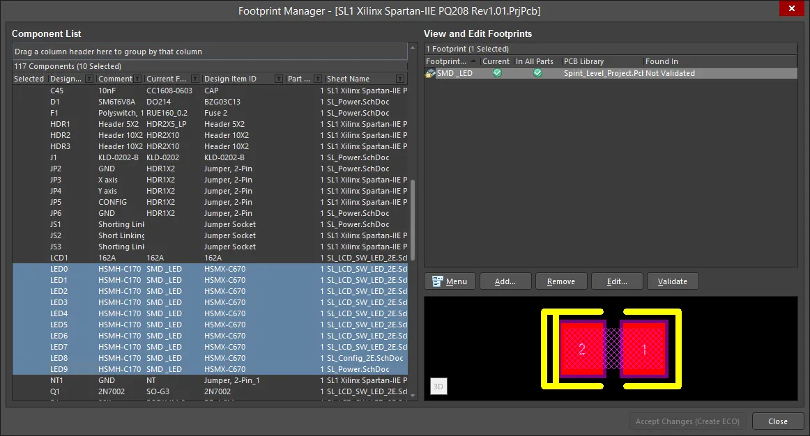
The Footprint Manager dialog presents a list of all components across all source design schematics in the active project. Use the controls available on the right-hand side of the dialog to manage the footprints available to, and in current use by, the design's components. Features include:
-
Ability to add, edit, and remove footprint models for one or more selected components.
-
Copy footprints between components.
-
Changing current footprint assignment (the footprint that will currently be used to represent a component in the PCB domain, from multiple that may be available to that component).
-
Footprint validation - to ensure that footprint models are truly available, and especially those set to be the current model.
Once all changes to footprint model assignments have been made as required, those changes are then implemented through a standard Engineering Change Order (ECO). To do this, simply click on the Accept Changes (Create ECO) button, at the bottom-right of the Footprint Manager dialog.
For a design containing device sheets, the components on those sheets will only be listed provided the sheets are not marked as being Read-only. Toggle the Read-only state for device sheets in projects from the
Data Management - Device Sheets page of the
Preferences dialog.
If the design has been captured using a range of libraries and the footprints have been manually attached or edited, it is imperative that a careful review of all footprint data is undertaken. The Footprint Manager can be used to help rationalize footprints across the design, but some level of sanity checking will also be required. There is no way for the system to catch design errors, such as specifying a 20W resistor onto a 0603 footprint. These all need to be reviewed carefully, and recognize that footprint names can vary across component suppliers. Do not assume anything!
Options and Controls of the Footprint Manager Dialog
Component List
This is a list of all components from the schematic sheets of the currently focused PCB design project. Information includes:
-
Designator
-
Comment
-
Current Footprint
-
Design Item ID
-
Part Count
-
Sheet Name
Click a component in this list to review its footprints in the list on the right. You can add, remove or edit footprints for the selected component.
-
To group the list, drag a column header to the area above the list where specified. The information will be grouped into a concise listing for easier readability. Click +/- to expand/contract grouped items.
-
Select All is available from the right-click menu to quickly select all components in the list.
View and Edit Footprints
This is a list of footprints associated with the selected component on the Component List. Use the controls at the bottom of the region or the right-click menu commands to manipulate the footprints in the list.
-
Click on a footprint to see a graphical view of that footprint in the region below.
-
Note that the Add, Remove and Edit commands/buttons are not available when a Workspace component is selected. Learn more about Workspace Components.
Right-click Menu
-
Add - click to open the PCB Model dialog to choose a new footprint model to add for the highlighted schematic component. Not available when a managed component is selected.
-
Remove - click to remove the selected footprint. Not available when a managed component is selected.
-
Edit Footprint - click to open the PCB Model dialog. The PCB Model dialog defines which footprint model is linked to the schematic component, and in which libraries the schematic editor can look for the footprint. Not available when a managed component is selected.
-
Validate Footprint Paths - click to confirm that the highlighted footprint can be found in the allowed location. If the footprint cannot be found, Not Validated appears in the Found In field. If the footprint is validated, a full path to this footprint is displayed.
-
Change PCB Library - click to open the Edit PCB Library dialog to change the PCB library of the selected footprint. This dialog is a simpler version of the PCB Model dialog, giving access to the PCB Library options to define where the software can look for footprint models.
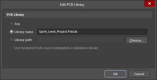
The Edit PCB Library dialog
-
Any - searches all available libraries for a matching model.
-
Library name - only searches available libraries of this name for a matching model.
-
Library path - only searches a library of this name, in this location, for a matching model. Either type the path and library name manually, or click the Choose button to open the Windows Open dialog, which you can use to browse to the required library.
-
Use footprint from source integrated library, database library, or server - only searches for the model in the integrated library/database library/server that the component was placed from. The integrated library or database library must be available or, for a server, you must be connected to that server.
-
Copy - click to copy the details of the currently selected footprint.
-
Paste - click to paste (add) the copied footprint details to the currently selected schematic component.
-
Select All - click to select all footprints currently visible in the View and Edit Footprints list.
-
Set As Current - click to set the selected footprint as the current footprint (denoted by a
 in the Current column).
-
Add to All Parts - click to add the selected footprint to all other Parts in the same schematic component (command only available if the selected component is a multi-part component, and one or more of the Parts in the component do not have this footprint specified).
Additional Controls
-
Menu - click to view a menu with the same controls as the right-click menu above.
-
Add, Remove, Edit, Validate - these buttons perform the same functions as the menu entries described above.
-
Accept Changes (Create ECO) - click to accept the changes to schematic components and their linked footprint models and execute the Engineering Change Order dialog. With the ECO dialog, you can validate and execute the changes after reviewing the modifications made to the footprint values for the corresponding schematic components.
