Altium Designer の PCB エディタ設定の定義

Altium Essentials: PCB Introduction
This content is part of the official Altium Professional Training Program. For full courses, materials and certification, visit Altium Training.
General
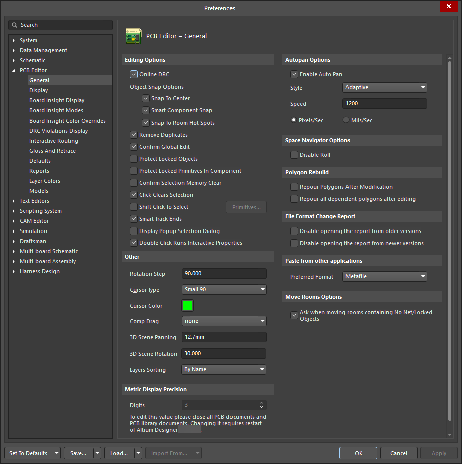
Editing Options
-
Online DRC – 有効にすると、作業中にソフトウェアがすべての PCB デザインルールをインタラクティブに監視し、ルール違反を即座にハイライト表示します。このオプションを無効にすると、作業中にはルール違反はハイライトされません。違反は、手動で Design Rule Check を実行したときにのみハイライトされます。 -
Object Snap Options -
Snap To Center – 有効にすると、オブジェクトを選択した際にカーソルが自動的にそのオブジェクト上の定義済み基準点へジャンプし、その点を「保持」した状態で再配置できるようになります。フリーパッドまたはビアを移動する場合、カーソルはオブジェクトの中心にスナップします。コンポーネントを移動する場合、カーソルはコンポーネントの基準点にスナップします。トラックセグメントを移動する場合、カーソルは頂点にスナップします。このオプションを無効にすると、オブジェクトはクリックした位置で「保持」されます。 -
Smart Component Snap – 有効にすると、コンポーネントをクリックして選択した際、カーソル位置に最も近い、そのコンポーネントに属するパッド上に十字カーソルが表示されます。このオプションを無効にすると、クリック時には常にそのコンポーネントのパッド基準点上に十字カーソルが表示されます。 -
Snap to Room Hot Spots – 有効にすると、カーソルがルームのホットスポットにジャンプします。
-
-
Remove Duplicates – 有効にすると、出力用データの準備時に重複プリミティブをチェックして削除します。ペンプロッタやベクターフォトプロッタなどのベクターデバイスに出力する場合は、このオプションを有効にします。 -
Confirm Global Edit – 有効にすると、グローバル編集アクションを実行する前に確認ダイアログが開き、そのアクションによって影響を受けるオブジェクト数が表示されます。確認ダイアログを使用して、必要に応じてグローバル編集をキャンセルできます。このオプションを無効にすると、グローバル編集ダイアログでOK ボタンをクリックした時点で、グローバル編集の変更が即座に適用されます。 -
Protect Locked Objects – 有効にすると、移動対象の選択に含まれていても、ロックされたオブジェクトは無視されます。 -
Protect Locked Primitives In Component - 有効にすると、コンポーネントプリミティブの変更を禁止します。 -
Confirm Selection Memory Clear – このオプションを有効にすると、選択メモリをクリアするかどうかを確認するダイアログがポップアップ表示されます。 -
Click Clears Selection – このオプションを有効にすると、マウスの左ボタンをクリックして現在の選択をクリアできます。 -
Shift Click To Select – 有効にすると、Primitives リストで指定された特定のプリミティブを選択する際にShift キーの使用を強制します。Primitives ボタンをクリックしてリストにアクセスします。このオプションを無効にすると、プリミティブは通常どおり選択されます。 -
Smart Track Ends – スマートトラックエンドがネットを再計算し、最短距離ではなくトラック終端から伸びるようにします。 -
Display popup selection ダイアログ – 有効にすると、同一位置に存在するオブジェクトを選択する際に PCB エディタでPopup Selection ダイアログを使用します。Popup Selection ダイアログは、(通常は異なるレイヤーにまたがる)重なり合ったオブジェクトの「スタック」内にあるオブジェクトを、より簡単に選択できるようにします。 -
Double Click Runs Interactive Properties – このオプションを有効にすると、配置済みオブジェクトをダブルクリックして編集する際にProperties パネルが開きます。無効にすると、配置済みオブジェクトをダブルクリックして編集する際にモーダルダイアログが開きます。
Other
-
Rotation Step –Spacebar を押したときに、カーソル上でフローティングしているオブジェクトに適用される回転量(度数)を示します。このフィールドを編集して角度を変更します(デフォルトは 90°)。最小角度分解能は 0.001° です。オブジェクトがカーソル上でフローティングしている状態でSpacebar を押すと、設定された角度分だけ反時計回りに回転します。時計回りに回転させるには、Shift キーを押しながらSpacebar を押します。 -
Cursor Type – ここで「アクション」カーソルの形状を定義します。このカーソルは、オブジェクトの配置や移動など、何らかの編集アクションを実行しているときに表示されます。クリックしてリストからカーソルタイプを表示・選択します。利用可能なカーソルは次のとおりです。-
Small 90 -
Large 90 -
Small 45Small 90
-
-
Cursor Color – クリックしてChoose Color ダイアログにアクセスし、使用する十字カーソルの色を選択します。 -
Comp Drag - コンポーネントをドラッグしたときに、接続されたトラックをどのように扱うかを示します。コンポーネントをドラッグするには、メインメニューからEdit » Move » Drag を選択し、ドラッグしたいコンポーネントをクリックします。クリックしてリストからオプションを表示・選択します。利用可能なオプションは次のとおりです。-
None -
Connected Tracks
-
-
3D Scene Rotation – 3D ビューコントロールに適用される回転量(度数)を示します。3D Scene Rotation 角度はデフォルトで30° -
3D Panning Rotation – 3D パン操作に適用されるパン量(ミリメートル)を示します。3D Panning distance step はデフォルトで500mils12.7mm -
Layer Sorting – ドロップダウンメニューを使用して、コンポーネントレイヤーペアおよびメカニカルレイヤーを View Configuration panelBy Name (デフォルト)またはBy Number (Legacy) のどちらでソートするかを選択します。
Metric Display Precision
- 3 桁精度の場合: 「5.255」
- 4 桁精度の場合: 「5.2547」
- 5 桁精度の場合: 「5.25467」
Autopan Options
-
Enable Auto Pan – 有効にすると、編集アクションを実行中で十字カーソルがアクティブなときに、カーソルをドキュメント表示ウィンドウの端より外側へ移動すると、その方向にドキュメントが自動的にパンします。 -
Style – ドロップダウンを使用して、ドキュメントのオートパンスタイルを選択します。利用可能なオプションは次のとおりです。-
Re-Center -
Fixed Size JumpStep Size の値で定義されたステップ量でパンします。Shift キーを押し続けると、Shift Step の値で定義されたステップ量でパンします。 -
Shift AccelerateStep Size の値で定義されたステップ量でパンします。Shift キーを押し続けると、Shift Step -
Shift DecelerateShift Step の値で定義されたステップ量でパンします。Shift キーを押し続けると、Step Size で定義された最小ステップサイズまでパン速度が減速します。 -
BallisticStep Size の値からShift Step の値まで増加します。Shift キーを押し続けると、Shift Step の値で定義されたステップ量でパンします。 -
Adaptive
-
-
Speed – 現在のオートパン速度を示します。このフィールドを編集して速度を変更します。測定単位はPixels/Sec またはMils/Sec オプションに従って設定されます。 -
Pixels/Sec – このオプションを選択すると、オートパン速度を 1 秒あたりのピクセル数で設定します。1 秒あたりのピクセル数はSpeed フィールドで設定します。 -
Mils/Sec – このオプションを選択すると、オートパン速度を 1 秒あたりの mil 数で設定します。1 秒あたりの mil 数はSpeed フィールドで設定します。
Space Navigator Options
-
Disable Roll – このオプションをオンにすると、Space Navigator 機能を無効にします。
Polygon Rebuild
-
Repour Polygons After Modification – 有効にすると、変更されたポリゴンを自動的に再ポアします。 -
Repour all dependent polygons after editing – 有効にすると、依存するすべてのポリゴンが自動的に再ポアされます。
File Format Change Report
-
Disable opening the report from older versions – 有効にすると、古い Altium Designer PCB ファイルフォーマットのドキュメントを開いたときにレポートをNOT 作成します。このレポートは、そのドキュメントが古いバージョンのソフトウェアで作成されたことを知らせ、開いたドキュメント内の一部の機能が失われる、または変更される可能性についての情報を提供します。このオプションはデフォルトでは無効です。 -
Disable opening the report from newer versions – 有効にすると、新しい PCB ファイルフォーマットが Altium Designer で読み込まれたときにレポートをNOT 作成します。このレポートは、そのドキュメントが新しいバージョンのソフトウェアで作成されたことを知らせ、開いたドキュメント内の一部の機能が失われる、または変更される可能性についての情報を提供します。このオプションはデフォルトでは無効です。
Paste from other applications
-
Metafile -
Text
Move Rooms Options
Display
Display Options
-
Antialiasing – チェックすると 3D でアンチエイリアスを有効にします。チェックを外すと無効にします。 -
Use Animation – ズーム、ボードの反転、レイヤー切り替え時のアニメーション表示をオン/オフするために使用します。
Highlighting Options
-
Highlight In Full – 有効にすると、選択されたオブジェクトが現在の選択色で完全にハイライト表示されます。このオプションを無効にすると、選択されたオブジェクトは現在の選択色で輪郭のみ表示されます。 -
Use Transparent Mode When Masking – 有効にすると、オブジェクトがマスクされているときに透過表示がオンになります(つまり、マスクの下にあるレイヤー上のオブジェクトが透けて見えるようになります)。 -
Show All Primitives In Highlighted Nets – 有効にすると、シングルレイヤーモード時に非表示レイヤー上のすべてのプリミティブと、ハイライトされたネットに対する現在のレイヤー上のプリミティブが表示されます。このオプションを無効にすると、シングルレイヤーモード時には現在のレイヤー上のすべてのプリミティブのみが表示され、マルチレイヤーモード時にはハイライトされたネットに対してすべてのレイヤー上のすべてのプリミティブが表示されます。 -
Apply Mask During Interactive Editing – インタラクティブ編集中に、選択されていないオブジェクトをマスクする場合に有効にします。マスクすることで、選択されていないオブジェクトが「フェード」され、編集中のオブジェクトに集中しやすくなります。 -
Apply Highlight During Interactive Editing – インタラクティブ編集モード中にオブジェクトをハイライト表示したい場合に有効にします(このとき、Highlight システムカラーが View Configuration panel で使用されます)。
Layer Drawing Order
この領域では、画面上でレイヤーが再描画される順序を設定できます。リストに表示されるレイヤーの順序が、そのまま再描画される順序になります。リストの一番上にあるレイヤーが、画面上の他のすべてのレイヤーの最前面に表示されるレイヤーです。リスト内のレイヤーを選択し、
-
Promote – クリックすると、選択したレイヤーを 1 つ上の位置に移動します。 -
Demote – クリックすると、選択したレイヤーを 1 つ下の位置に移動します。 -
Default – クリックすると、Layer Drawing Order をシステムデフォルトにリセットします。
Board Insight Display

Pad and Via Display Options
-
Use Smart Display Color – 有効にすると、パッドおよびビアの詳細表示に使用するフォント特性をソフトウェアが自動的に制御します。このオプションを無効にすると、フォント特性を手動で設定できます。 -
Font Color – クリックすると標準のChoose Color ダイアログが開き、パッド/ビア詳細表示用のフォント色を選択できます。このフィールドは、Use Smart Display Color オプションが有効な場合は使用できません。 -
Transparent Background – 有効にすると、背景を表示せずにパッド/ビアの詳細を表示します。このオプションを無効にすると、Background Color フィールドを使用して特定の色を適用できます。このオプションは、Use Smart Display Color オプションが有効な場合は使用できません。 -
Background Color – クリックすると標準のChoose Color ダイアログが開き、パッド/ビア詳細に使用する背景色を選択できます。このフィールドは、Use Smart Display Color オプションが有効な場合、またはそのオプションが無効でもTransparent Background オプションが有効な場合は使用できません。 -
Min / Max Font Size – ズームレベルに関係なく、パッドおよびビアの詳細表示に使用される最小および最大フォントサイズを表示します。これらのフィールドを編集して、最小および最大フォントサイズを変更します。 -
Font Name – パッドおよびビアの詳細表示に使用される現在の TrueType フォントを表示します。クリックしてリストからフォントを表示および選択します。 -
Font Style – パッドおよびビアの詳細表示に使用される現在の TrueType フォントスタイルを表示します。クリックしてリストからオプション(Bold ,Bold Italic ,Italic ,Regular )を表示および選択します。 -
Minimum Object Size – パッドおよびビアの詳細を表示するオブジェクトの現在の最小サイズ(画面ピクセル単位)を表示します。これはズームレベルに関係なく適用されるため、低いズームレベルでもパッドおよびビアの詳細の視認性を維持できます。希望のサイズを入力するか、上下の矢印を使用します。
Available Single Layer Modes
-
Hide Other Layers - シングルレイヤーモードでは、選択されたレイヤーのみが表示され、他のレイヤーは非表示になります。 -
Gray Scale Other Layers - シングルレイヤーモードでは、選択されたレイヤーがハイライトされ、他のレイヤー上のすべてのプリミティブはグレースケールで表示されます。 -
Monochr ome Other Layers - シングルレイヤーモードでは、選択されたレイヤーがハイライトされ、他のレイヤー上のすべてのプリミティブは同じ濃さのグレーで表示されます。
Live Highlighting
-
Live Highlighting only when Shift Key Down – このオプションを有効にすると、Shift キーが押されている場合にのみライブネットハイライトが適用されます。 -
Outline Color – クリックすると標準のChoose Color ダイアログが開き、使用するアウトライン色を選択できます。
Show Locked Texture on Objects
ロックされたテクスチャは、ロックされたオブジェクトとロックされていないオブジェクトを簡単に見分けるための視覚的な手がかりです。ロックされたオブジェクトのテクスチャは「鍵」のように表示されます。次のいずれかのオプションを有効にします:
-
Never – このオプションを有効にすると、ロックされたオブジェクトに対してロックテクスチャを一切表示しません。 -
Always – このオプションを有効にすると、ロックされたオブジェクトに対して常にロックテクスチャを表示します。 -
Only When Live Highlighting – このオプションを有効にすると、そのオブジェクトがライブハイライト機能によってハイライトされているときにのみ、ロックされたオブジェクトのロックテクスチャを表示します。
Board Insight Modes

Display
-
Display Heads Up Information - このオプションを有効にすると、Heads Up Display をオンにします。表示される情報は、通常ステータスバーに表示されるグリッド座標、レイヤー、寸法、アクションなどです。ステータスバーを見る代わりに、視線を上げてデザイン空間内でこの情報を確認できます。
-
Use Background Color - このオプションを有効にすると、Heads Up 情報が背景を透過して表示されます。 -
Insert Key Resets Heads Up Delta Origin - このオプションを有効にすると、Insert キーが押されたときに、現在のカーソル位置で Delta Origin を 0, 0 にリセットします。カーソルが Delta Origin から水平方向および垂直方向に移動した距離は、Heads Up Display に表示できます(Shift +D )。 -
Mouse Click Resets Heads Up Delta Origin - このオプションを有効にすると、マウスクリックにより、現在のカーソル位置で Delta Origin を 0, 0 にリセットします。カーソルが Delta Origin から水平方向および垂直方向に移動した距離は、Heads Up Display に表示できます(Shift +D )。 -
Hover Mode Delay - ホバー表示情報が現れるまで、カーソルをアイテム上にどのくらいの時間置いておくかを制御するために使用します。上下の矢印ボタンをクリックして(100ms 単位で増減)またはスライドコントロールを使用して、時間遅延を増減します。 -
Heads Up Opacity - 上下の矢印ボタンをクリックする(1%刻みで変化)か、スライドコントロールを動かして Heads Up ディスプレイモードの不透明度レベルを増減し、表示を見えにくく/見えやすくします。ダイアログ下部のプレビューペインで、表示がどのように見えるかを確認できます。 -
Hover Opacity - 上下の矢印ボタンをクリックする(1%刻みで変化)か、スライドコントロールを動かしてホバーディスプレイモードの不透明度レベルを増減し、表示を見えにくく/見えやすくします。ダイアログ下部のプレビューペインで、表示がどのように見えるかを確認できます。
Insight Modes
-
Grid - このグリッドには、Heads Up ディスプレイモードでどの情報を表示するかの利用可能なオプションが一覧表示されます。表示したい情報タイプについて、Heads Up およびHover 列のチェックボックスを有効にします。Panel 列のオプションは、Properties パネルに表示される情報を指します。Popup 列のオプションは、オブジェクト (Shift+X ) および違反 (Shift+V ) ポップアップウィンドウを使用しているときに表示される情報を指します。Font 列のオプションは、Heads Up ディスプレイモード内の表示テキストを制御します。 -
Heads Up Preview - Heads Up 情報のプレビューを表示します。 -
Hover Preview - カーソルが一定時間静止しているときに、そのカーソル位置の基板情報のプレビューを表示します。
Board Insight Color Overrides
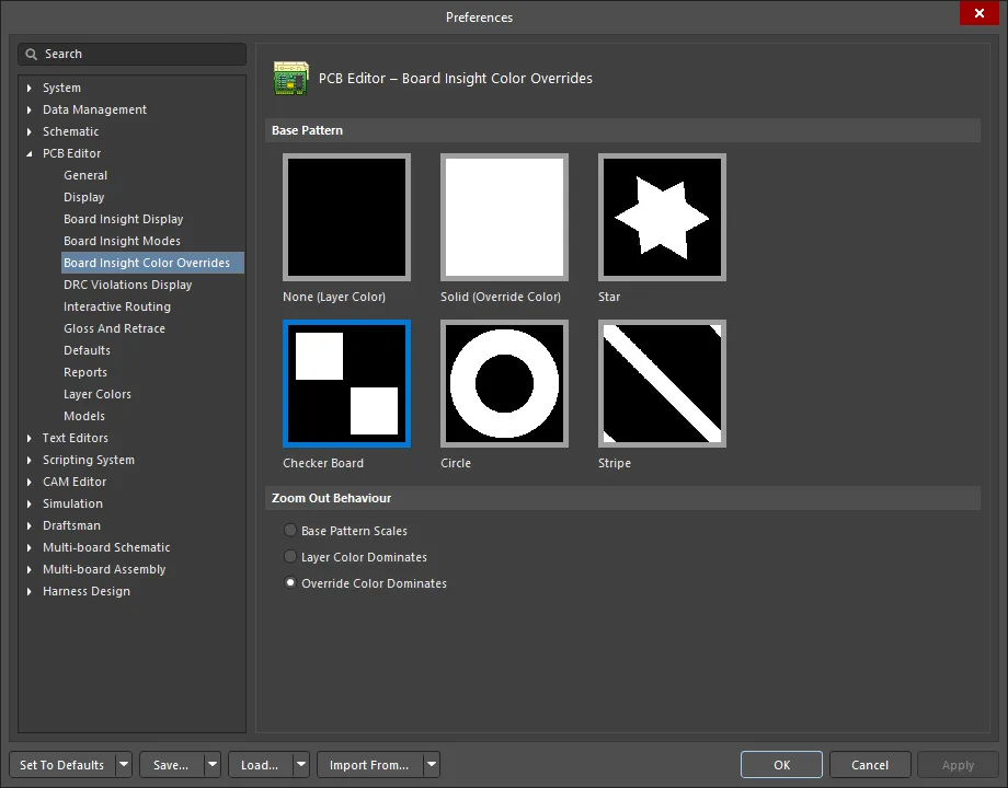
Base Pattern
ボードインサイトカラーオーバーライド用のベースパターンを選択します。利用可能なパターンは
Zoom Out Behavior
これらのオプションを使用して、ズームアウトしたときのネットの表示方法を指定します。
-
Base Pattern Scales - ズームアウト時にベースパターンをスケーリングする場合に選択します。 -
Layer Color Dominates - ズームアウトするほど、割り当てられたレイヤーカラーをより優先的に表示し、最終的にパターン色が目立たなくなるようにする場合に選択します。 -
Override Color Dominates - ズームアウトするほど、割り当てられたネットオーバーライドカラーをより優先的に表示し、最終的にパターン色が目立たなくなるようにする場合に選択します。
DRC Violations Display

Violation Overlay Style
PCB デザイン空間で違反をどのように表示するかを指定するため、ビジュアルオーバーレイスタイルを選択します。次のオプションから選択できます。
-
None (Layer Color) - DRC オーバーライドカラーを無視し、デフォルトのレイヤーカラーのみを表示します。 -
Solid (Override Color) - DRC オーバーライドカラーを使用し、デフォルトのレイヤーカラーを完全に上書きします。 -
Style A - DRC オーバーライドカラーを感嘆符タイプのパターン表示に使用し、デフォルトのレイヤーカラーも同時に表示します。 -
Style B - DRC オーバーライドカラーをクロスタイプのパターン表示に使用し、デフォルトのレイヤーカラーも同時に表示します。
Overlay Zoom Out Behavior
これらのオプションを使用して、ズームアウトしたときのオーバーレイの表示方法を指定します。
-
Base Pattern Scales - ズームアウト時にベースパターンをスケーリングする場合に選択します。 -
Layer Color Dominates - ズームアウトするほど、割り当てられたレイヤーカラーをより優先的に表示し、最終的にパターン色が目立たなくなるようにする場合に選択します。 -
Override Color Dominates - ズームアウトするほど、割り当てられたネットオーバーライドカラーをより優先的に表示し、最終的にパターン色が目立たなくなるようにする場合に選択します。
Choose DRC Violations Display Style
この領域には、ルールごとに使用する表示スタイルを選択できるグリッドが表示されます。
-
ルールタイプに対して
Violation Details フィールドを有効にすると、そのルールの DRC 違反を表示するために、関連付けられたカスタム違反グラフィックが使用されます。 -
Violation Overlay フィールドを有効にすると、指定されたオーバーレイスタイルを使用して違反が表示されます。
この領域内で右クリックするとコンテキストメニューにアクセスでき、すべてのルールタイプに対して違反表示タイプの使用を一括で有効/無効にするコマンドを利用できます。また、現在デザインで使用されているルールに対してのみ、違反の表示(詳細グラフィックまたはオーバーレイスタイル)をすばやく有効にすることもできます。
Interactive Routing
Routing Conflict Resolution
-
Ignore Obstacles - インタラクティブルータが、既存オブジェクト上も含めて任意の場所にトラックを配置できるようにし、潜在的な違反を表示しつつも許容する場合に選択します。 -
Push Obstacles - インタラクティブルータが、配線中に既存トラックを押しのけて移動させるようにする場合に選択します。このモードでは、新しい配線のためにビアを押すこともできます。システムが違反を発生させずに障害物を押しのけられない場合、ルートがブロックされていることを示すインジケータが表示されます。 -
Walkaround Obstacles - インタラクティブルータが、配線中に既存のトラック、パッド、ビアの周囲を回り込んで配線し、それらを移動させようとしないようにする場合に選択します。システムが違反を発生させずに障害物を回避できない場合、ルートがブロックされていることを示すインジケータが表示されます。 -
Stop At First Obstacle - インタラクティブルータが、進行方向の最初の障害物に遭遇した時点で配線を停止するようにする場合に選択します。このモードでは、配線は本質的に手動となり、障害物に遭遇するとすぐに、違反を避けるようにトラックセグメントがクリップされます。 -
Hug And Push Obstacles - インタラクティブルータが、配線中に既存のトラック、パッド、ビアに可能な限り密着して配線し、必要に応じて Walkaround を継続できない場合には障害物を押すようにする場合に選択します。システムが違反を発生させずに障害物に密着または押すことができない場合、ルートがブロックされていることを示すインジケータが表示されます。このモードは効率的には Walkaround と Push を組み合わせたものです。 -
AutoRoute On Current Layer - 現在のレイヤーでの自動配線を有効にする場合に選択します。このモードでは、インタラクティブルータに基本的なオートルータのインテリジェンスが適用され、プッシュ距離と回り込み距離、およびルート長を考慮するヒューリスティクスに基づいて、プッシュと回り込みのどちらを使用するかを自動的に選択し、全体として最短のルート長を実現します。オートルータと同様に、このモードは単純で未配線の基板よりも、複雑で混雑した基板でより良い結果をもたらすことがあります。 -
AutoRoute On Multiple Layers - 複数レイヤーでの自動配線を有効にする場合に選択します。このモードでも、インタラクティブルータに基本的なオートルータのインテリジェンスが適用され、プッシュ距離と回り込み距離、およびルート長を考慮するヒューリスティクスに基づいて、プッシュと回り込みのどちらを使用するかを自動的に選択し、全体として最短のルート長を実現します。このモードではビアを配置し、他の配線レイヤーの使用も検討できます。オートルータと同様に、このモードは単純で未配線の基板よりも、複雑で混雑した基板でより良い結果をもたらすことがあります。 -
Current Mode - このフィールドには、インタラクティブルータ使用時に選択されている現在の Routing Conflict Resolution モードが表示されます。必要に応じて、関連付けられたドロップダウンを使用してモードを変更します。
Interactive Routing Options
-
Automatically Terminate Routing – 有効にすると、ターゲットパッドまでの配線を完了した際に、ルーティングツールはターゲットパッドfrom で配線モードを継続せず、リセットされて次に配線を開始するソースパッドをクリックできる状態になります。このオプションを無効にすると、ターゲットパッドまで配線した後もツールは配線モードのままとなり、次の配線では直前のターゲットパッドがソースとして使用されます。 -
Automatically Remove Loops – 手動配線中に生成される不要なループを自動的に削除できるようにします。これにより、冗長なトラックを手動で削除することなく、接続を再配線できます。ただし、電源ネットなど、ループが必要なネットを配線しなければならない場合もあります。その場合は、PCB パネルからEdit Net ダイアログを開き、選択したネットのネットプロパティを編集して、そのネットに対するRemove Loops オプションを切り替えることができます。指定したネットに対するRemove Loops のローカル設定は、同じネットに対するこのグローバル設定を上書きします。-
Remove Loops with Vias – ビアを含むループを自動的に削除するには有効にします。ループ削除の際にビアを残したい場合は、このオプションを無効にします。 -
Remove Net Antennas – 他のいかなるプリミティブにも接続されておらず、アンテナを形成しているトラックまたはアークの端部を自動的に削除するには有効にします。
-
-
Allow Via Pushing – 上記のCurrent Mode で選択したPush Obstacles またはHugNPush Obstacles モード中にビアをプッシュできるようにするには、このオプションを有効にします。 -
Display Clearance Boundaries – このオプションを有効にすると、インタラクティブ配線中に、既存オブジェクトと適用されるクリアランスルールによって定義される進入禁止クリアランス領域がシェーディングされたポリゴンとして表示され、配線に利用可能なスペースを視覚的に把握できます。-
Reduce Clearance Display Area – 既定では、すべてのクリアランス境界が表示されますが、このオプションを有効にすると、表示範囲をローカライズされた表示円内に入る境界のみに絞り込むことができます。
-
-
Apply Trace Centering – トレースセンタリング機能を有効にします。有効にすると、可能な場合には配線中のネットと既存のパッド/ビアとの間に追加クリアランスが設けられ、次のオプションでその動作を設定できます。-
Adjust Vias – このオプションを有効にすると、可能な限り追加クリアランスを維持するようにビアがプッシュされます。 -
Added Clearance Ratio – 適用されるクリアランスに対する倍率であり、その値がクリアランスに加算されます。たとえば、適用クリアランスが0.15 mm2 に設定すると、可能な限り既存のパッドおよびビアから0.15 + 2 * 0.15 = 0.45 mm
トレースセンタリングの詳細については、Interactive Routing ページを参照してください。
-
-
Auto Shrinking – このオプションを有効にすると、現在選択されている配線幅では障害物間を通せない箇所で配線できるよう、自動的に配線幅を縮小します。配線の自動シュリンクの詳細については、Interactive Routing ページを参照してください。
General
最小限のコーナー数で配線を行えるようにするため、
-
Gloss Effort (Routed) – にはOff 、Weak 、Strong の 3 つの設定があります。配線中にCtrl+Shift+G ショートカットを使用して設定を切り替えます。-
Off – このモードでは、実質的にグロッシングは無効になります。ただし、たとえば重なり合うトラックセグメントを除去するために、配線/ドラッグ後のクリーンアップは依然として実行される点に注意してください。このモードは、(トラックの手動ドラッグやパッドエントリのクリーンアップなど)最終的な微調整が必要となるボードレイアウトの終盤で有用です。 -
Weak – このモードでは、低レベルのグロッシングが適用され、インタラクティブルータは現在配線中のトラック(またはドラッグ中のトラック/ビア)に直接接続されている、あるいはその周辺にあるトラックのみを考慮します。このグロッシングモードは、トラックレイアウトの微調整やクリティカルなトレースを扱う際に有用です。 -
Strong – このモードでは、高レベルのグロッシングが適用され、インタラクティブルータは最短経路の探索やトラックのスムージングなどを行います。このグロッシングモードは、ボードレイアウトの初期段階で、ボードの大部分を素早く配線することを目的とする場合に有用です。
プッシュ&シャブのインタラクティブ配線では、新しい配線のためのスペースを確保するために既存の配線を押しのけることができます。その結果、既存配線の新しい位置は設計ルールを満たしていても、その配置品質が損なわれる場合があります。これを管理するため、インタラクティブ配線のグロッシングツールは、プッシュ&シャブ処理の影響を受けたすべての既存配線をグロッシングする
neighbor ルートをサポートします。 -
-
Gloss Effort (Neighbor) – にはOff 、Weak 、Strong の 3 つの設定があります。配線中にCtrl+Shift+G ショートカットを使用して設定を切り替えます。 -
Hugging Style – ドロップダウンから 45 度、ミックス、ラウンドのハギングスタイルを選択します。 -
Minimum Arc ratio – 希望する最小アーク比を入力します。最小アーク比は、任意角度インタラクティブ配線およびMixed Hugging スタイルでのインタラクティブスライド中に適用される場合があります。この比率は、アーク半径がこの最小値を下回ったときに、そのアークをトラックセグメントに置き換えるかどうかを決定するために使用されます。Min Arc Radius = Min Arc Ratio x Arc Width. -
Miter Ratio – 希望するマイター比を入力します。これは最小コーナーのきつさを制御するために使用できます。x 乗数は自動的に付加されます)。 -
Pad Entry Stability – センタリングされたパッドエントリに対する保護レベルを入力します。数値が大きいほど保護が強くなり、'0 ' は保護なしを意味します。
Dragging
-
Preserve Angle When Dragging - このオプションを有効にすると、ドラッグ中に角度を保持します。有効にした場合、次のいずれかのオプションを選択します。-
Ignore Obstacles -
Avoid Obstacles (Snap Grid) -
Avoid Obstacles
-
-
Disable Trace Centering When Dragging - このオプションを有効にすると、(Apply Trace Centering オプションが有効な場合でも)インタラクティブスライド中にトレースセンタリングは適用されません。 -
Vertex Actions - 頂点をクリックしてドラッグしたときに使用される、希望する頂点アクションを選択します。トラックやアークではなく頂点をクリック&ドラッグした場合に適用される、特定のオプションがあります(頂点とは、2 つのセグメントが交わるコーナー位置です)。スライド中にSpacebar ショートカットを使用して、利用可能なモードを順送りに切り替えます。ドロップダウンのオプションには次が含まれます。-
Deform - 移動中の頂点に接続されているトラックセグメントを分割または延長し、頂点がカーソルの動きに追従するようにします。 -
Scale - コーナー形状を保持したまま、頂点をカーソルに追従させつつ、進入側トラックセグメントのサイズ変更と移動を行います。 -
Smooth - コーナーを滑らかに再形成し、内側にドラッグしたとき(Mixed または Rounded Hugging Style の場合)に、スライド処理の影響を受けるすべての頂点で曲線コーナーを作成するためのアークを挿入します。また、Rounded Hugging Style では外側にドラッグしたときにもアークを追加します。
-
-
Unselected via/track - 未選択のビアまたはトラックをドラッグしたときのデフォルト動作を、MoveDrag -
Selected via/track - 選択済みのビアまたはトラックをドラッグしたときのデフォルト動作を、MoveDrag -
Component pushing - このフィールドには、デザイン空間内でコンポーネントを移動する際の現在の Component Conflict Resolution モードが表示されます。サポートされているモードは次のとおりです。-
Ignore - デフォルト動作であり、隣接するコンポーネントとの違反が発生する場合でもコンポーネントを移動できます。このモードでは、以前のバージョンの Altium Designer で使用されていたものと同じコンポーネントクリアランスチェックルーチンが使用されます。これらのルーチンは、3D ボディ(存在する場合)または銅・シルクのプリミティブを使用してオブジェクトのクリアランスを判定します。 -
Push - コンポーネントは他のコンポーネントを押しのけて移動し、コンポーネント間のクリアランスを満たすようにします。ユニオン内のコンポーネントも押しのけることができ、ユニオン内のコンポーネント位置は変化する場合がありますが、ユニオン自体は分解されません。ロックされたコンポーネントは押しのけることができません。このモードでは、コンポーネントは選択境界によって識別されます。選択境界とは、そのコンポーネント内のすべてのプリミティブを囲む最小の長方形です。 -
Avoid - コンポーネントは、他のコンポーネントとのコンポーネントクリアランスルール違反を回避するように強制されます。このモードでも、コンポーネントは選択境界によって識別されます。選択境界とは、そのコンポーネント内のすべてのプリミティブを囲む最小の長方形です。
-
-
Component re-route - ボックスをオンにして、ドロップ後の接続性復元を切り替えます。移動していたオブジェクト群を解放した後、ソフトウェアはコンポーネントを再配線し、切断されたネットを再接続しようとします。Shift+R ショートカットを使用して、この再配線動作を抑止(オプションを無効化)できます。なお、コンポーネントがユニオンのメンバーである場合、そのコンポーネントには再配線は適用されません。 -
Move component with relevant routing - このオプションを有効にすると、関連する配線(Components +Via Fanouts +Escapes +Interconnects)を含めてコンポーネント移動アクションを開始します。Shift+Tab ショートカットを使用して選択セットを順送りに切り替えます。オプションを無効にすると、コンポーネントのみが選択された状態でコンポーネント移動アクションを開始します。関連する配線オブジェクトのセットは移動開始前に検出されるため、オプションが無効な場合はShift+Tab を使用して選択セットを順送りに切り替えることはできません。-
up to -Move component with relevant routing オプションが有効な場合に、ピン数を指定します。デフォルト値は 2 です。コンポーネントのピン数がこのフィールドで指定した数より多い場合、Move component with relevant routing オプションは「機能せず」、関連する配線はコンポーネントと一緒には移動されません。
-
Interactive Routing Width Sources
-
Pickup Track Width From Existing Routes - 配置済みトラックから配線を継続する際に既存のトラック幅を使用するには、このオプションを有効にします(つまり、現在の配線幅が既存トラックと異なる場合でも、ルートを継続するときに既存トラックの幅が採用されます)。 -
Track Width Mode - インタラクティブルーティング用のトラック幅モードを選択します。利用可能なモードは次のとおりです。-
User ChoiceChoose Width ダイアログで選択された幅によって決定されます。このダイアログには、配線中にShift+W -
Rule Minimum -
Rule Preferred -
Rule Maximum
-
-
Via Size Mode - インタラクティブルーティング用のビアサイズモードを 1 つ選択します。利用可能なモードは次のとおりです:-
User ChoiceChoose Via Sizes ダイアログで選択されたサイズによって決定されます。このダイアログには、配線中にShift+V -
Rule Minimum -
Rule Preferred -
Rule Maximum
-
Favorites

注意事項:
- 網掛けされていないエントリは、それらの幅が選択されたときに優先システム単位が使用されることを示します。ボード単位は自動的に切り替わります。
-
エントリをダブルクリックするか(または選択して
Edit ボタンをクリックする)と、Preferred Routing Width ダイアログが開き、必要に応じて幅の値を変更できます。 -
Add ボタンをクリックしてPreferred Routing Width ダイアログを開き、リストに新しい配線幅を追加します。単位なしで値を入力した場合、デフォルトでImperial 優先システム単位が使用されます。幅に使用される優先システム単位を制御するには、必ず単位を指定してください(特にMetric が必要な場合)。
Preferred Routing Width ダイアログ
Gloss と Retrace

Gloss & Retrace パラメータ
-
Hugging Style – グロスまたはリトレース中のコーナー形状の扱い方法を制御します。-
45 Degree – グロスまたはリトレース中にコーナーを作成する際、常に直交/斜めの直線セグメントを使用します(従来の直交/斜め配線動作にはこのモードを使用します)。 -
Rounded – グロスまたはリトレースに関与する各頂点でアークを使用します。グロス時にアーク+任意角度配線を使用する場合にこのモードを使用します。
-
-
Avoid polygons – このオプションを有効にすると、Gloss Selected またはRetrace Selected コマンド実行時に既存のポリゴンが尊重されます。オプションが無効な場合、既存のポリゴンは無視され(上を配線され)、影響を受けたポリゴンは再ポアできます。 -
Avoid rooms – このオプションを有効にすると、Gloss Selected またはRetrace Selected コマンド実行時に既存のルームが尊重されます。設計内に特定の配線幅要件でスコープされたルームが定義されており、グロス/リトレース対象の配線がそのルームを横切っていない場合、このオプションが有効であれば、結果として得られる配線もそのルームを横切りません。オプションが無効な場合、既存のルーム上も配線され、そのようなルーム内で使用される幅はルームベースルールの制約で定義された値になります。 -
Pad Entry Stability – 中心パッドへのエントリに対する保護レベルを入力します。数値が大きいほど保護が強くなります。'010 -
Miter Ratio – 最小コーナーのきつさを制御します。Miter Ratio に現在のトラック幅を掛けた値が、その比率で配線可能な最もきつい U 字形の壁間隔になります。0 以上の正の値を入力してください。
Gloss パラメータ
-
Weak – このモードでは、低レベルのグロスが適用されます。このモードは、トラックレイアウトの微調整やクリティカルなトレースを扱う場合に有用です。 -
Strong – このモードでは、高レベルのグロスが適用され、最短経路が強く重視されます。このモードは、レイアウトプロセスの初期段階で、ボードの多くを素早く配線したい場合に有用です。
Retrace パラメータ
-
Set Width – ドロップダウンを使用して、Retrace Selected コマンド実行時に適用される Width または Differential Pairs Routing 設計ルールのルールベース幅オプション(Min /Max /Preferred )のいずれか、またはリトレース対象トラックのCurrent 幅を選択します。あるいは、希望するカスタム幅値をフィールドに直接入力します。 -
Set Diff Pair Gap – ドロップダウンを使用して、Retrace Selected コマンド実行時に適用される Differential Pairs Routing 設計ルールのルールベースギャップオプション(Min /Max /Preferred )のいずれか、またはリトレース対象の差動ペアトラック間のCurrent ギャップを選択します。あるいは、希望するカスタムギャップ値をフィールドに直接入力します。 -
Preserve route path – Retrace 中にトレースの正確なジオメトリを保持する場合に有効にします。このオプションが有効な場合、Retrace アルゴリズムはトレースのセンターラインを変更しません。トラックは幅が変わったり、異なる幅のセグメントに分割されたりすることがありますが、軌跡自体は変更されません。
True Type Fonts
PCB エディタにおける TrueType フォントサポートの詳細については、PCB Placement & Editing Techniques ページを参照してください。
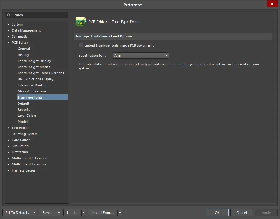
TrueType Fonts 保存/読み込みオプション
-
Embed TrueType fonts inside PCB documents - TrueType フォントは、コンピュータにインストールされているフォントです。この設定を有効にすると、PCB ファイル内で使用した TrueType フォントを保存できます。これにより、特定のフォントを持たない他のマシンでも、意図したとおりのデザイン表示が可能になります。 -
Substitution font - 代替フォントは、開いたファイルに含まれているものの、システムに存在しない TrueType フォントを置き換えます。ドロップダウンを使用して希望するフォントを選択します。
Defaults

Default Primitives
-
Primitives - このフィールドを使用して、表示されるプリミティブの一覧をフィルタリングします。 -
Primitive List - PCB エディタで使用できるプリミティブの一覧です(上記のPrimitives フィールドで選択したエントリに従ってフィルタリングされます)。一覧のPrimitives をクリックして、利用可能なデフォルト値を変更します。各プリミティブの設定とオプションを表示および編集するには、
Primitive List 内の目的のエントリをクリックします。PCB デザインオブジェクトの詳細については、QuickNav - PCB Design Objects ページを参照してください。
Additional Controls
-
Save as - 現在のデフォルトオブジェクトプロパティをカスタムプロパティファイル (*.dft ) に保存するにはクリックします。ファイル名とディレクトリの指定を求められます。PCB エディタサーバーが起動すると、現在のデフォルトが読み込まれ、終了時にデフォルトに対して行った変更がこのファイルに保存されます。以前に保存したデフォルトプロパティセットを読み込むには、Load ボタンを使用します。 -
Load - 以前に保存したデフォルトオブジェクトプロパティセットを読み込むにはクリックします。以前に保存したプロパティファイル (*.dft ) を選択するよう求められます。 -
Reset All - すべてのオブジェクトのプロパティをシステムデフォルトにリセットするにはクリックします。 -
Permanent - このオプションが有効な場合、すべてのオブジェクトタイプのデフォルトプロパティはロックされ、配置中にオブジェクトのプロパティを編集しても変更されません。このオプションが無効な場合、配置中に特定のオブジェクトに対して行った変更(オブジェクトがカーソル上でフローティングしている配置前の状態でTab キーを押してProperties パネルを開くことで行う)が、そのオブジェクトタイプのデフォルトプロパティを更新するために使用されます。
Reports

Reports
このリストに表示される PCB レポートは、テキスト、HTML、または XML ファイルとして作成できます。レポート作成後に表示(オープン)するには
サポートされているレポートは次のとおりです:
- Design Rule Check
- Net Status
- Board Information
- BGA Escape Route
- Move Component(s) Origin to Grid
- Embedded Boards Stackup Compatibility
Layer Colors
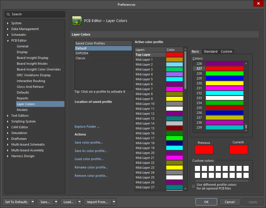
Layer Colors
-
Saved Color Profiles - 現在保存されているカラープロファイル名を一覧表示します。エントリをクリックして「アクティブ化」します。これにより、そのプロファイルでレイヤーに設定されている色をActive color profile 領域で確認し、必要に応じて変更できます。 -
Location of saved profile - 保存された 2D カラープロファイルのファイルパスを表示します。Saved Color Profiles リスト内のエントリにカーソルをホバーすると、そのパスがここに表示されます。 -
Explore Folder - 保存されたカラープロファイルが格納されているフォルダを開くにはクリックします。 -
Actions – この領域では、ファイルレベル (*.PCBSysColors-
Save color profile – 現在選択されているカラープロファイルに対して行ったレイヤー色の変更を保存するにはクリックします。 -
Save As color profile –Save Color Profile As ダイアログにアクセスするにはクリックします。ここから、現在選択されているカラープロファイルを別名の新しいプロファイルとして保存できます。新しく保存されたカラープロファイルは、保存済みカラープロファイルのリストに追加されます。 -
Load color profile –Load Color Profile File ダイアログにアクセスするにはクリックします。ここから、カラープロファイルファイル (*.PCBSysColors -
Rename color profile – 必要に応じてプロファイルの新しい名前を指定できるRename Color Profile ダイアログにアクセスするにはクリックします。 -
Remove color profile – 選択したカラープロファイルを削除するにはクリックします。確認ダイアログが表示されます。保存済みカラープロファイルリストからプロファイルを削除するにはNo をクリックします。カラープロファイルファイルもハードディスクから削除したい場合はYes をクリックします。
-
-
Active color profile - この領域では、アクティブなカラープロファイル、すなわちSaved Color Profiles リストで現在選択されているプロファイルのレイヤー色を設定するためのコントロールを提供します。 -
Layers - サポートされているすべてのボードレイヤーおよびシステムレイヤーを一覧表示します。各レイヤーについて、右側のカラースウォッチに現在割り当てられている色が表示されます。レイヤーの色を変更するには、リストでそのレイヤーを選択し、右側のコントロールを使用して新しい色を選択します。 -
Selection region - レイヤーリストの右側の領域には、標準のChoose Color ダイアログにあるものと同じコントロールが用意されています。タブは 3 つあり、必要なレイヤー色を選択するためのシンプルモードおよび詳細モードを提供します:-
Basic - このタブは色をフラットなリストとして提供します。 -
Standard - このタブは、一般的な色で満たされた六角形のカラセレクタと、黒・白・各種グレーを素早く選択するためのコントロールを提供します。 -
Custom - このタブは、必要な色合いを正確に得るための詳細なコントロールを提供します。メインのカラエリアで十字カーソルをドラッグしておおよその色を選択し、右側の垂直スライダーバーで色合いを微調整します。Color model ドロップダウンフィールドを使用して、RGB (Red, Green, Blue) またはHSL (Hue, Saturation, Luminance) の 2 つのカラーモデルから選択します。上部のカラコントロールを変更すると、下のフィールドが更新されます。あるいは、Red 、Green 、Blue
-
-
Previous - 選択したレイヤーに以前使用されていた色を表示します。 -
Current - レイヤーに対して新しく選択された色を表示します。この色は、ソフトウェアの現在の編集セッション中(OK をクリックするだけの場合)に適用されるか、プロファイルを保存した場合はそのカラープロファイルに反映されます。 -
Custom Colors - この領域では、最大 16 個のカスタムカラーを保存できます。カラ選択コントロールで目的の色をようやく得た場合に、その色を再利用するために「保存」しておくのに便利です。任意のカスタムカラースウォッチをクリックすると、その色が現在のレイヤー色として素早く割り当てられます。-
Add to Custom Colors - 現在選択されている色をカスタムカラーパレットに追加するにはこのボタンを使用します。
-
-
Use different profile colors for all opened PCB files - このオプションを有効にすると、開いているすべての PCB ドキュメントに対して、割り当てられたプロファイルに従ってレイヤー色が表示されます。このオプションはデフォルトでは無効です。
Models
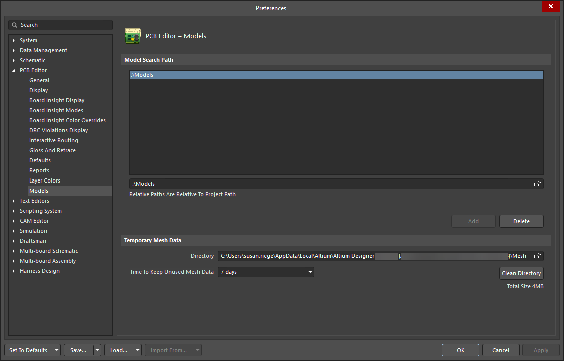
Model Search Path
-
Models 領域 -3D Body モードの Properties パネルを介してlinking 3D STEP モデルファイルを扱う際に、デフォルトで参照されるすべてのフォルダを一覧表示します。これらのフォルダは、ソフトウェアがその中の STEP ファイル (*.stp ,*.step ) の変更を監視するため、「監視対象」と見なすことができます。 -
Models path - 右側の参照アイコンをクリックしてダイアログを開き、3D STEP モデルファイルを検索するフォルダーを参照します。フォルダーが見つかったら、Models 領域にあるAdd ボタンを使用して追加します。コンポーネントのフットプリントや PCB ドキュメントに STEP モデルをリンクまたは埋め込むときは、Models 領域リストに表示されているフォルダーがデフォルトで使用されます。STEP モデルファイル用に共通または集中管理された保管場所を使用するという考え方は、特にマルチユーザー環境において有益です。 -
Add - 参照バーに現在表示されているフォルダーをModels 領域リストに追加するにはクリックします。 -
Delete - 現在選択されているフォルダーをModels 領域リストから削除するにはクリックします。
Temporary Mesh Data
-
Directory - ソフトウェアが 3D モデルのメッシュデータを保存するフォルダーを参照するためのダイアログを開くには、フォルダー参照アイコンをクリックします。メッシュデータは、3D モデルが最初に使用または作成されたときに、表示目的で計算されます。このデータは保存され、同じモデルが再度必要になったときに使用されます。このようにメッシュデータを保存することで、3D 設計空間で作業する際のシステムパフォーマンスを向上させることができます。 -
Time To Keep Unused Mesh Data - システムが 3D モデルのメッシュデータを最後に使用してから削除するまでの最大保存期間(日数)を表示および選択するにはクリックします。メッシュデータは、3D モデルが最初に使用または作成されたときに、表示目的で計算されます。このデータは保存され、同じモデルが再度必要になったときに使用されます。このようにメッシュデータを保存することで、3D 設計空間で作業する際のシステムパフォーマンスを向上させることができます。利用可能なオプションは次のとおりです:-
1 day -
2 days -
7 days -
30 days
-
-
Clean Directory - 一時的な 3D モデルメッシュデータを保存するために使用されているフォルダーを即座に空にするにはクリックします。


 AI で翻訳