In mechanical CAD software, the concept of relating two objects in space is a fundamental part of the design process, which is a process known as mating those two objects. When two objects have been mated they can be manipulated as a single object. These mated objects can then be mated to another object, and through this process, a set of discrete objects are formed into an assembly - the very essence of mechanical design. Basically, objects are no longer related by aligning and positioning them, now they are mated.
A mate is a connection formed between two separate objects. The connection is at a user-selected point on a surface on each object. Once mated the objects will re-orient so their surface planes and their perpendicular axes are aligned.
Definitions:
- Target - the first site nominated as a Mate site.
- Source - the second site nominated; this object will move to mate with the Target.
- Mating axis - the perpendicular axis passing through the center of the Mate.
Defining Mates
To define a mate, perform the following steps:
- Click the
 button on the Active Bar to switch to Mating mode (or Tools » Mating from the main menus or use the Shift+Ctrl+A shortcut). The mating process requires one click to define each mate site but further clicks can be used when needed as described in the Notes paragraph below.
- While in mating mode, hover the cursor over an object to be mated. As the cursor is positioned over a surface on the object, that surface will change color (to gray) and display potential mate sites (glyphs).
- On a planar surface select from nine glyphs that are located at the center, corners and mid-points of the bounding rectangle.
- On a cylindrical surface select from two glyphs that are located along the axis at each end of the cylinder.
- Each glyph is a potential mate site. The glyph that is currently closest to the cursor is highlighted by a larger green dot. Click the cursor anywhere over the surface to accept the highlighted glyph as the first mate site. This is the Target for the Mate. Once selected, the Target is marked by a purple dot.
- As the cursor is moved off the surface, it will turn green indicating that the Target lies on that surface.
- Repeat this process on the second object to define the second mate site (the Source). The Source is highlighted using a brown dot.
- As soon as the Source is defined, the Source object will move so that the Source site and the Target site are mated (located together), with their surface planes and perpendicular axes aligned. The Mate location is indicated by a circular arc that remains visible through other objects (when the Mate is selected), and the perpendicular axis of the mate location is displayed using a dashed purple line.
- When objects are mated, they are locked together and move as a single object.
- To modify an existing Mate, select it in the Multiboard Assembly panel, then edit its values in the Properties panel.
Notes:
- The Status bar indicates when you are in mating mode.
- If it is difficult to select a glyph, for example, selecting the center of a hole in an object (demonstrated in the video below), or the wrong glyph was selected, you can change the Target glyph before moving on to define the Source glyph.
- As the cursor continues to be moved over the plane containing the Target, each glyph highlights in green when it becomes closest to the cursor. The current Target remains highlighted in purple. If a different glyph is required, position the cursor to highlight it in green, then left-mouse click to nominate it.
- If it is not possible to define a Mate on a mounting screw, hide the screw (right-click on the object in the Multiboard Assembly panel) and use the screw hole instead.
- The second mate site must be located on a different object from the first mate site. If a second surface is selected on the same object as the first mate site, the action is interpreted as choosing a new first mate site.
- Mated objects can be mated to a third object.
- The workspace view can be changed while you are defining a Mate:
- Ctrl+Right click and drag to zoom in/out.
- Shift+Right click and drag to pivot the workspace view around the click location.
- Press Esc to abort the mating process and drop out of Mating mode.
Simple demonstration of defining a Mate be tween a nut and a screw. The Status bar indicates when you are in Mate definition mode, or mate editing mode.
Modifying a Mate
To modify a Mate, right-click on its entry in the Multiboard Assembly panel then choose Properties, or double-click it in the Multiboard Assembly panel. Use the Mate mode of the Properties panel to adjust its settings. Note that the Status bar indicates when the mate is in editing mode.

Properties Panel
When the active document is a Multi-board Assembly document (*.MbaDoc) and a Mate is selected, the Properties panel presents the Mate mode.

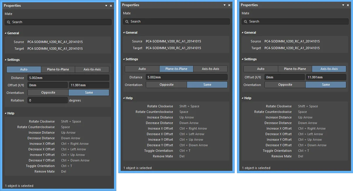
The Properties panel in Mate mode
The following collapsible sections contain information about the options and controls available:
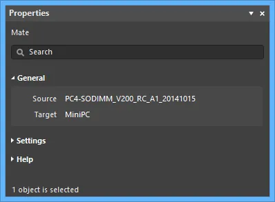
General

- Source – the second site nominated. This object will move to mate with the Target.
- Target – the first site nominated as a Mate site.
Settings

- Auto – the Mate is locked in all directions; dragging either object will move both. Once the objects have been positioned correctly, use this mode to ensure their location relationship is not inadvertently changed by dragging an object in the design space.
- Distance – the distance between the mates' closest edges/surfaces. Use the field to adjust the distance, moving the Source along the mating axis. The mating axis is the perpendicular axis passing through the center of the Mate.
- Offset (X/Y) – the offset of the Source in the X and Y directions across the Target mating plane.
- Orientation – select the orientation of the mates, either Opposite or Same.
- Rotation – the rotation of the mates.
- Plane-to-Plane – the Mate is locked along the mating axis but can be interactively dragged across the X/Y plane. The mating axis is the perpendicular axis passing through the center of the Mate.
- Distance – the distance between the mates' closest edges/surfaces. Use the edit field to adjust the Distance, moving the Source along the mating axis.
- Orientation – select the orientation of the mates, either Opposite or Same.
- Axis-to-Axis – the Mate is locked in the X/Y plane but can be interactively dragged along the mating axis. The mating axis is the perpendicular axis passing through the center of the Mate.
- Offset (X/Y) – the offset of the source in the X and Y directions across the Target mating plane. The Target remains stationary.
- Orientation – select the orientation of the mates, either Opposite or Same.
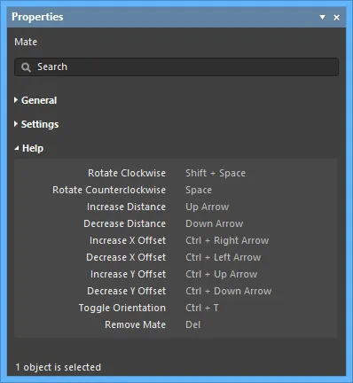
Help

The Help region displays some of the shortcuts that are available while working with mates.
