Altium Designerには、回路図、回路図ライブラリ、PCBまたはPCBライブラリドキュメントからDXF/DWGファイルをインポートおよびエクスポートする機能が含まれています。
インポート
アクティブなAltium Designerの回路図またはPCBドキュメントにDXF/DWGファイルをインポートするには、対応するエディタのメインメニューからFile » Import » DXF/DWGコマンドを選択します。アクティブなAltium Designerの回路図またはPCBライブラリにDXF/DWGファイルをインポートするには、対応するエディタのメインメニューからFile » Import » AutoCADコマンドを選択します。Import Fileダイアログが開き、必要なDXF/DWGファイルを参照して選択できます。その後、グラフィックデータのインポートを制御するImport from AutoCADダイアログが開きます。

Import from AutoCADダイアログ(回路図または回路図シンボル)
Import from AutoCAD (SCH)ダイアログのオプションとコントロール
ブロック
-
Import as components – インポーターはAutoCADブロック(プリミティブオブジェクトのグループ化されたコレクション)を単一のコンポーネントとして解析し、これらを回路図ライブラリに追加しようとします。
-
Import as primitives – インポーターは、ブロック内のオブジェクトを含むすべてのAutoCADオブジェクトデータをプリミティブ/ベースオブジェクト(線、弧など)として解析します。
AutoCADからAltium Designerへの線幅マッピング(mm)
AutoCADの線データが名目上の非数値幅定義(Smallest、Smallなど)を使用している場合、インポーターはここで指定された幅寸法(mm)にこれらをマッピングします。Large線幅は自動的に決定されます。
スケール
目標ドキュメントに合わせてAutoCADインポートのスケーリング係数を設定します。インポートされたグラフィックの境界定義(Sizeとして報告される)が目標の回路図シート(Sheet size)よりも大きい場合、関連するサイズテキストは赤色で表示されます。
単位がMilsに設定されて作成されたソースDXF/DWGファイルは、インポート時に1:1の比率でスケールされる可能性が高いです。
AutoCAD(0,0)を配置する場所

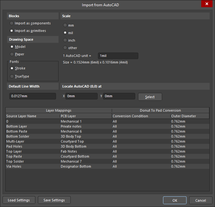
Import from AutoCADダイアログ(PCBまたはPCBフットプリント)
Import from AutoCAD (PCB)ダイアログのオプションとコントロール
ブロック
-
Import as components – インポーターはAutoCAD ブロック(プリミティブオブジェクトのグループ化されたコレクション)を複合オブジェクトとして解析し、ドキュメント上にPCBコンポーネントとして配置しようとします。
-
Import as primitives – インポーターは、ブロック内のオブジェクトを含むすべてのAutoCADオブジェクトデータをプリミティブ/ベースオブジェクト(線/トラック、弧など)として解析します。
描画スペース
AutoCAD DXF/DWG形式では、ModelスペースとPaperスペースの2つの描画環境が含まれています。AutoCADでは、描画ソースは無限の3Dモデルスペースにあり、ページ印刷の準備として2Dペーパースペースにリサイズすることもできます。保存されたDXF/DWGファイルには、モデルスペースのデータまたはモデルとペーパースペースの両方のデータが含まれることがあります。
-
Model– ファイルのモデルスペースデータから描画ソースグラフィックとその寸法情報を抽出するように設定します。寸法データは真のスケーリング(1:1)です。これは信頼できるインポートプロセスのための推奨設定です。
-
Paper – 描画ソースグラフィックとその寸法情報を、ファイルのペーパー空間データから抽出するように設定するには選択します。ソースファイルでは、ペーパー空間の寸法情報は指定されたページサイズとレイアウトに合わせてスケーリングされています。なお、ペーパー空間データがDXF/DWGファイルに含まれていない場合、このオプションを選択すると描画データがインポートされない可能性があります。
フォント
DXF/DWGファイルから変換されるテキストオブジェクトのフォントタイプをStrokeまたはTrueTypeのいずれかから選択します。
既定の線幅
ソースのAutoCADファイル内の線オブジェクトに幅データが含まれていない場合に適用される既定の線幅。
スケール
単位スケーリングは、DXF/DWGファイルからデータをインポートする際に使用されます。可能であれば、元のファイルが生成された際に指定されたソースデータファイルで使用されている単位に一致する単位オプションを選択してください。不正確な単位の選択は、ファイルがインポートされる際に明らかなスケーリングエラーを引き起こすことが通常です。
AutoCAD原点の配置
レイヤーマッピングとドーナツからパッドへの変換表
この領域を使用して、AutoCADファイル内の名前付きレイヤーがAltium Designerレイヤーにどのようにマッピングされるか、ドーナツ形状(弧状円)がパッドに変換されるかを指定します。
追加のコントロール
Export
Altium Designerの回路図またはPCBドキュメントは、DXF/DWGファイル形式にエクスポートできます。Outputjobファイルで、[Add New Export Output]をクリックし、AutoCAD dwg/dxf PCBまたはAutoCAD dwg/dxf Schematicメニューのエントリを選択します。エクスポート出力は、ファイルから直接生成するか、プロジェクトリリースプロセスの一部として生成できます。

または、Altium Designerの回路図またはPCBエディタのメインメニューからFile » Export » DXF/DWGコマンドを選択します。
Altium Designerの回路図やPCBライブラリをDXF/DWGファイル形式にエクスポートするには、対応するライブラリエディタのメインメニューからFile » Export » AutoCADコマンドを選択します。
OutJobファイルの一部としてエクスポートする場合でも、Fileメニューから直接エクスポートする場合でも、関連するExport to AutoCADダイアログでエクスポートのオプションを設定できます。
-
回路図(または回路図ライブラリ)からエクスポートする場合、以下のダイアログを使用して設定を行います:

必要に応じてバージョン、形式、単位を設定します。回路図の場合、エクスポートされたAutoCADファイルに現在のテンプレートグラフィックスを含めるには、Include Templateオプションが有効になっていることを確認してください。
-
PCB(またはPCBライブラリ)からエクスポートする場合、以下のダイアログを使用して設定を行います:

Export to AutoCADダイアログのオプションとコントロール
DXFフォーマットのファイルは、メインメニューのFile » Import from DXFとFile » Export to Dxfコマンドを使用して、ドラフトマン文書にインポートしたりエクスポートしたりすることもできます。
Supported Versions of AutoCAD
DXF/DWG形式のデザインのインポート/エクスポートは、以下のAutoCADバージョンでサポートされています:
-
AutoCAD 2018 (DWG 2018ファイル形式がこのリリースで導入されました).
-
AutoCAD 2013 (DWG 2013ファイル形式がこのリリースで導入されました).
-
AutoCAD 2010 (DWG 2010ファイル形式がこのリリースで導入されました).
-
AutoCAD 2007 (DWG 2007ファイル形式がこのリリースで導入されました).
-
AutoCAD 2004 (DWG 2004ファイル形式がこのリリースで導入されました).
-
AutoCAD 2000 (DWG 2000ファイル形式がこのリリースで導入されました).
-
AutoCAD R14 (DWG R14ファイル形式がこのリリースで導入されました).
-
AutoCAD R13 (DWG R13ファイル形式がこのリリースで導入されました).
-
AutoCAD R12 (DWG R11/R12ファイル形式がこのリリースで導入されました).
Supported Object Types
デザインをAltium Designerにインポートする際、またはエクスポートする際にサポートされているDWG/DXFオブジェクトタイプは以下の通りです:
-
Arc
-
Circle
-
Dimension
-
Ellipse
-
Elliptical Arc
-
Hatch
-
Insert
-
Leader
-
Line
-
Multileader
-
Multiline
-
Multitext
-
Point
-
Polyline
-
Rectangle
-
Region
-
Solid
-
Spline
-
Text
-
Trace
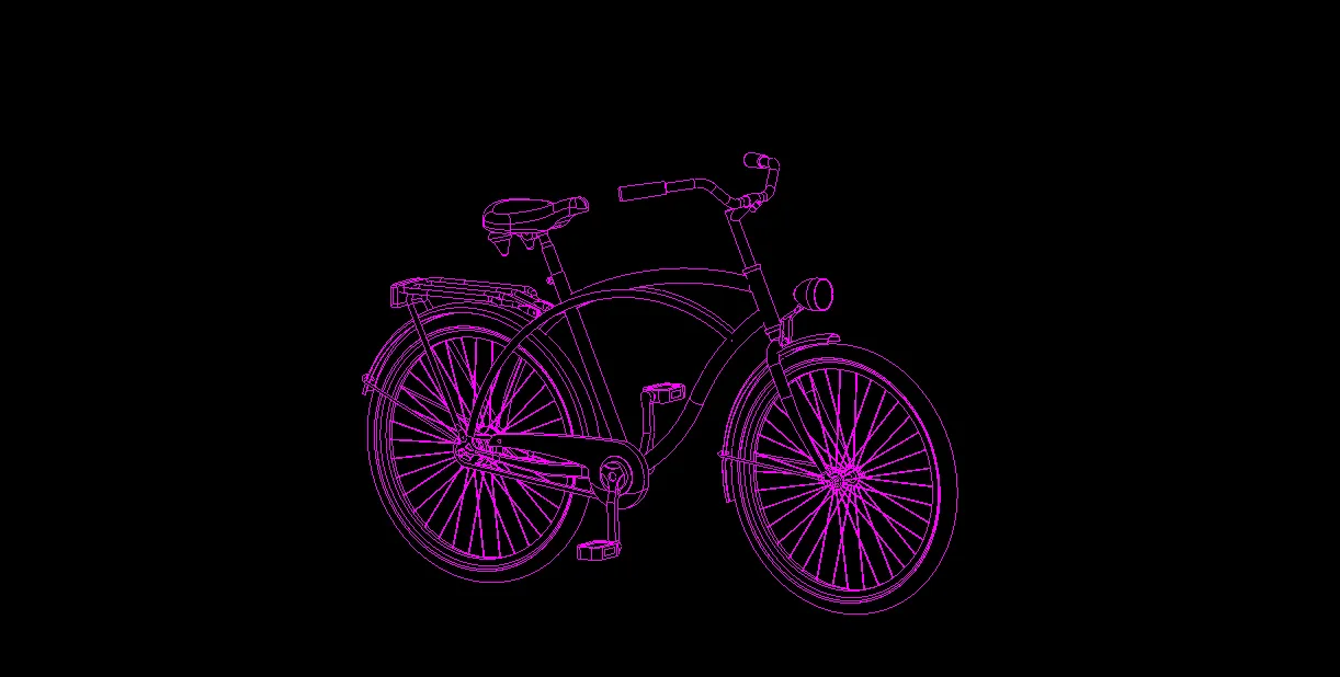
 Altium DesignerのPCBエディタ用のAutoCAD DWG/DXFインポーターの向上した柔軟性を示す例です。この特定の楽しい図面は、元々AutoCAD 2013で描かれ、DWG 2013ファイル形式で保存されており、スプライン、ポリライン、アークオブジェクト(エンティティ)で構成されています。
 別の例として、今回はDWG 2013フォーマットのファイルがAltium Designerのスキーマティックエディタにインポートされました。