Parent page: Multi-board Panels

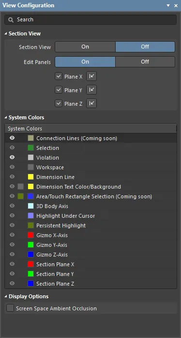
The Multi-board Assembly editor's View Configuration panel.
Summary
The View Configuration panel is used to configure the color and workspace visibility options in the Multi-board Assembly editor. It is also used to control the display of the section view, and the section panels.
Panel Access
When a Multi-board assembly document is active, the panel can be accessed in the following ways:
- Click View » Panels » View Configuration.
- Click the
 button at the bottom-right of the work area and select the View Configuration menu option.
Content and Use
The panel content is divided into three sections:
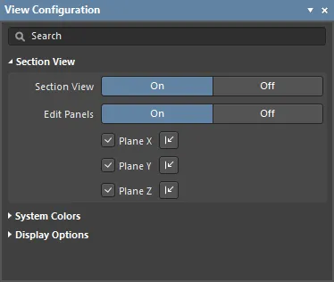
- Section View - options to enable and configure the section view feature, and control the display of the section panels.
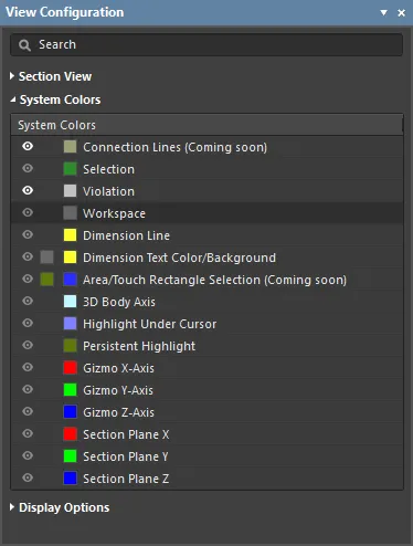
- System Colors - options to configure the visibility and color of layers.
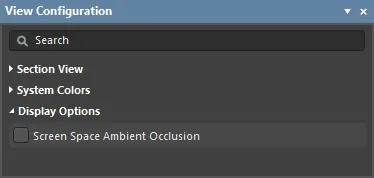
- Display Options - an option to enable ambient occulsion in the workspace.
The content is arranged in two collapsible sections that are opened and closed using the ► icon associated with each section heading. The information included below is arranged by matching sections, and each collapsible section is opened/closed in the same manner.
In the Multi-board Assembly editor, each workspace axis, and its corresponding plane, is assigned a color:
- Blue - Z axis, viewing into the X-Y plane. You can think of this as the top or bottom view.
- Red - X axis, viewing into the Y-Z plane. You can think of this as the front or rear view.
- Green - Y axis, viewing into the X-Z plane. You can think of this as the left or right view.
Section View

A section view is a view that can be used to reveal detail within an assembly, that might normally not be visible. This is achieved by defining a plane where a section of the assembly is sliced or cut away. The Multi-board Assembly editor supports defining a section plane along each of the 3 axes, allowing the section definition to be in 1, 2 or 3 directions.
- Section View - enable/disable the section view feature. When this option is enabled, the colored Edit Planes will be displayed. The default location is to define the section at the geometric center of the assembly, in all 3 planes. The Section View can also be toggled on/off using the Shift+Ctrl+V shortcuts.
- Edit Panels - the panels are used to define the section location - that is, the location of the cut in each plane. Each panel includes a small arrow control, click, hold and drag on the arrow to change the location of that section plane. Alternatively, click and hold anywhere on the panel and move it, the software will attempt to select and move the panel under the cursor. When the Edit Panels Off button is clicked the panels are hidden, giving a clearer view of the sectioned assembly. Alternatively, use the Shift+Ctrl+E shortcuts to toggle the panels off and on. Note that the section plane colors continue to be applied to any object surface that is cut by the section, after the panels have been hidden.
- Section Plane controls - these controls are used to enable sectioning in each plane, and to toggle on which side of that plane the assembly's content is to be removed.
| Plane |
Enable Plane |
Change Plane Direction |
|
X Plane
|

View » Toggle Section Plane X
1 shortcut key
|

View » Flip Section Plane X
Ctrl+1 shortcut
|
|
Y Plane
|

View » Toggle Section Plane Y
2 shortcut key
|

View » Flip Section Plane Y
Ctrl+2 shortcut
|
|
Z Plane
|

View » Toggle Section Plane Z
3 shortcut key
|

View » Flip Section Plane Z
Ctrl+3 shortcut
|
The color of each section plane is configured in the System Colors section of this panel.
EXAMPLE IMAGES
System Colors

Setting the Color
Each layer includes a small color button, click this to display the color selector, as shown below.

The panel includes:
- A history row, showing (up to) the last 10 color choices that were made.
- A grid of 10 x 8 predefined color buttons, click a button to select that color.
- A Custom Color row of up to 10 custom colors.
Custom colors can be defined, to do this:
- Click Define Custom Colors to expand the color palette to also display the Custom Color Palette.
- Use the horizontal slider in the center of the Custom Color Palette to select a base color, then click anywhere on the palette to brighten or darken that color.
- Alternatively, enter the Hex or RGB values into the appropriate fields in the Custom Color Palette.
- Click the Apply button to add the new color to the Custom Color row, and apply that color to the layer being edited.
Displaying or Hiding a Workspace Feature
Certain workspace features (such as Selection), can be displayed or hidden. Click the eye icon (  ) to toggle the visibility off and on. If the icon is grayed out, the visibility of that layer cannot be changed.
Display Options

Ambient occlusion is a method used to approximate how bright the light should be shining on any specific part of a surface, based on the light and that surface's environment (how hidden/open it is to the ambient light source).
- Screen Space Ambient Occlusion - enabling this option will generally add more contrast and detail to the displayed surfaces, creating a greater sense of realism and making it easier to interpret the image. The image below shows a section of a heatsink without ambient occulsion applied. Move your cursor over the image to apply ambient occulsion, note how the extra visual detail in the heatsink fins makes it easier to interpret the image.
 A section of a heatsink, without ambient occlusion applied - hover the cursor over the image to enable ambient occulsion.
