Parent page: Workspace Content Types
Helping to streamline the creation of your components, Altium Designer, in conjunction with your connected Workspace, supports creating and defining Component Templates (Component Template Items) in that Workspace. Just as a schematic template can be used to predefine information on schematic sheets that reference it, a component template is referenced by a Workspace library component and provides predefined settings for use when defining that component.
In particular, component templates have been developed with parametric information firmly in mind, allowing you to define, in a single location, a 'bucket set' of parameters that will be made available to the referencing component. Through the template, you can control which of those parameters are to be made visible, fill-in default values, and even mark those parameters that are required as mandatory. Validation checks are in place at the time of component saving, to ensure compliance.
Specified default values for many of the template settings can be locked-down to be read-only or selectively made available for override by the designer when defining a component.
Such component templates are created directly from within the Workspace. Once a component template has been created (and data saved into a revision of it), it can be reused in the creation of one or more components.
Folder Type
When creating the folder in which to store component templates, you can specify the folder's type. This has no bearing on the content of the folder – releasing a component template will always result in a corresponding Component Template Item. It simply provides a visual 'clue' as to what is stored in a folder and can be beneficial when browsing a Workspace for particular content. To nominate a folder's use as a container for component templates, set its Folder Type as Component Templates, when defining the folder properties in the Edit Folder dialog.
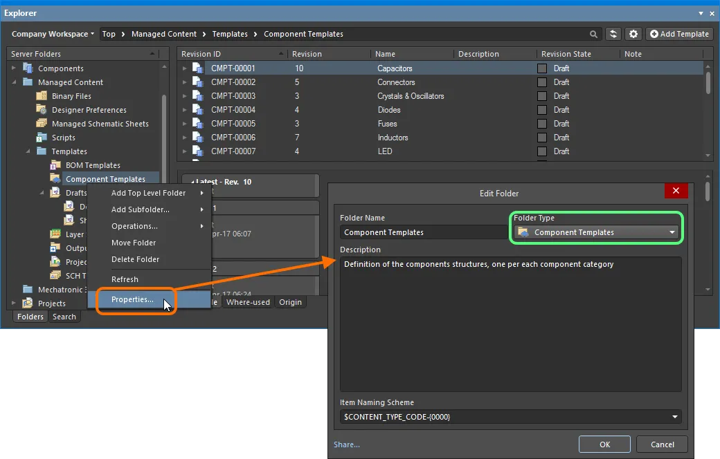
Specifying the folder type – its intended use – gives a visual indication of the content of that folder when browsing the Workspace.
Item Naming Scheme
Another important aspect of the parent folder is the Item Naming Scheme employed for it. This defines the format of the unique ID for each Item created in that particular folder. Several default example schemes are available, utilizing the short-form code for either the folder type (CTC – Component Template Collection) or the content type (CMPT – Component Template):
$CONTENT_TYPE_CODE-001-{0000} – for example, CMPT-001-0001.$CONTENT_TYPE_CODE-001-{A00} – for example, CMPT-001-A01.$FOLDER_TYPE_CODE-001-{0000} – for example, CTC-001-0001.$FOLDER_TYPE_CODE-001-{A000} – for example, CTC-001-A001.
Using a default naming scheme, the software will automatically assign the next available unique ID, based on that scheme, having scanned the entire Workspace and identifiers of existing content. This can be a great time-saver when manually creating component templates.
A custom scheme can also be defined for a folder, simply by typing it within the field, ensuring that the variable portion is enclosed in curly braces (e.g. CMP-TMP-{0000}).
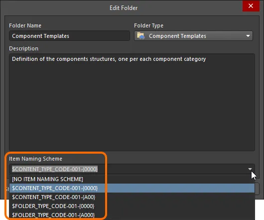
The Item Naming Scheme of the parent folder is applied to the Unique ID for each Item created within that folder.
The Item Naming Scheme employed for the parent folder can be changed at any time. The modified scheme will then be applied to any subsequent newly-created content within that folder.
Content Type
When creating a target Component Template Item in which to store your component template, ensure that its Content Type is set to Component Template, in the Create New Item dialog. If you are creating the Item in a Component Templates type folder, this content type will be available from the right-click context menu when creating the Item.

Creating a component template within a Component Templates folder – the correct Content Type is available on the context menu.
Item Lifecycle Definition and Revision Naming
Related pages: Defining Revision Naming Schemes for a Workspace, Defining Lifecycle Definitions for a Workspace
When defining a component template, be sure to specify the type of lifecycle management to be used for the component template, and the naming scheme employed for its revisions, respectively.
Control over which content types can use a particular lifecycle definition or revision naming scheme can be defined and enabled at a global level from within the Content Types dialog when defining each schema. The default schemes assigned for use by a component template are: Generic Lifecycle and 1-Level Revision Scheme, respectively.
Once a template definition has been saved into the initial revision of a Component Template Item, these schemes cannot be changed for that particular Item.
Specify the required schemes in the Create New Item dialog, using the Lifecycle Definition and Revision Naming Scheme fields respectively.
If the option to control use of lifecycle definitions and revision naming schemes per content type is enabled for any definitions/schemes, and the Component Template content type is not set to use a particular definition/scheme, then that definition/scheme will not be available in the applicable drop-down list.
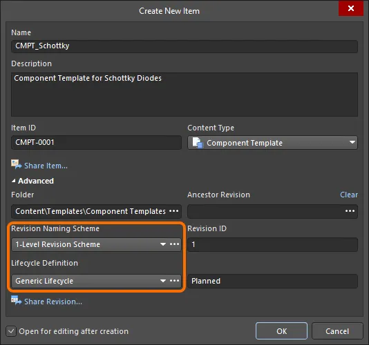
Selecting the Lifecycle Definition and Revision Naming schemes for a manually created component template.
Observing standard revision naming schemes and lifecycle definitions, across the various types of design content in a Workspace ensures smooth, consistent management of this content.
It is a good idea to add a Name and Description as part of the component template's definition. This information is used when searching the Workspace and enables quick identification of what a component template offers.
Saving a Component Template
Related page: Creating and Editing Content Directly through a Workspace
So far, we've discussed the support for a component template in the Workspace, in terms of related folder and content types. Saving an actual defined component template into a revision of such a Component Template Item can be performed in a streamlined way.
A component template can be edited and saved into the initial revision of a newly-created Component Template Item, courtesy of the Workspace's support for direct editing. Direct editing frees you from the shackles of separate version-controlled source data. You can simply edit a supported content type using a temporary editor loaded with the latest source direct from the Workspace itself. And once editing is complete, the entity is saved (or re-saved) into a subsequent planned revision of its parent Item, and the temporary editor closed. There are no files on your hard drive, no questioning whether you are working with the correct or latest source, and no having to maintain separate version control software. The Workspace handles it all, with great integrity, and in a manner that greatly expedites changes to your data.
When you create a Component Template Item, you have the option to edit and save a component template into the initial revision of that Item, after creation. To do so, enable the option Open for editing after creation, at the bottom of the Create New Item dialog (which is enabled by default). The Item will be created and the temporary Component Template Editor will open, presenting a .CMPT document as the active document in the main design window. This document will be named according to the Item-Revision, in the format: <Item><Revision>.CMPT (e.g. CMPT-0001-1.CMPT).
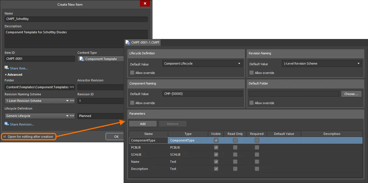
Example of editing the initial revision of a component template, directly from the Workspace – the temporary Component Template Editor provides the document with which to define your component template.
Use the document to define the component template as required. For more information on doing this, see Defining the Template.
There are three relevant controls when direct editing, readily available from the Quick Access Bar (at the top-left of the main application window), or from the Component Template Standard toolbar:
-
 – Save Active Document. Use this button to locally save any changes made to the document. This allows you to save current changes, should you wish to come back at a later stage to make further changes before ultimately saving to the Workspace.
-
 /
/ – Save to Server. Use this button to save the defined component template to the Workspace, storing it within the initial (planned) revision of the target Component Template Item. The Edit Revision dialog will appear, in which you can change Name, Description, and add release notes as required. The document and editor will close after the save. The document containing the source component template,
 *.CMPT will be stored in the revision of the Item.
A
Save to Server control is also conveniently provided to the right of the component template's entry, within the
Projects panel itself.
-
 /
/ – Discard Local Changes. Use this button if you wish to cancel editing and discard any changes made. The document and editor will close, and nothing will be released to the target Component Template Item.
These controls are also available as commands – Save (Shortcut: Ctrl+S), Save to Server (Shortcut: Ctrl+Alt+S), and Discard Local Changes – from the main File menu and from the right-click menu of the component template's entry in the Projects panel.
The saved data stored in the Workspace consists of the source component template, defined in the Component Template file (<Item><Revision>.CMPT).
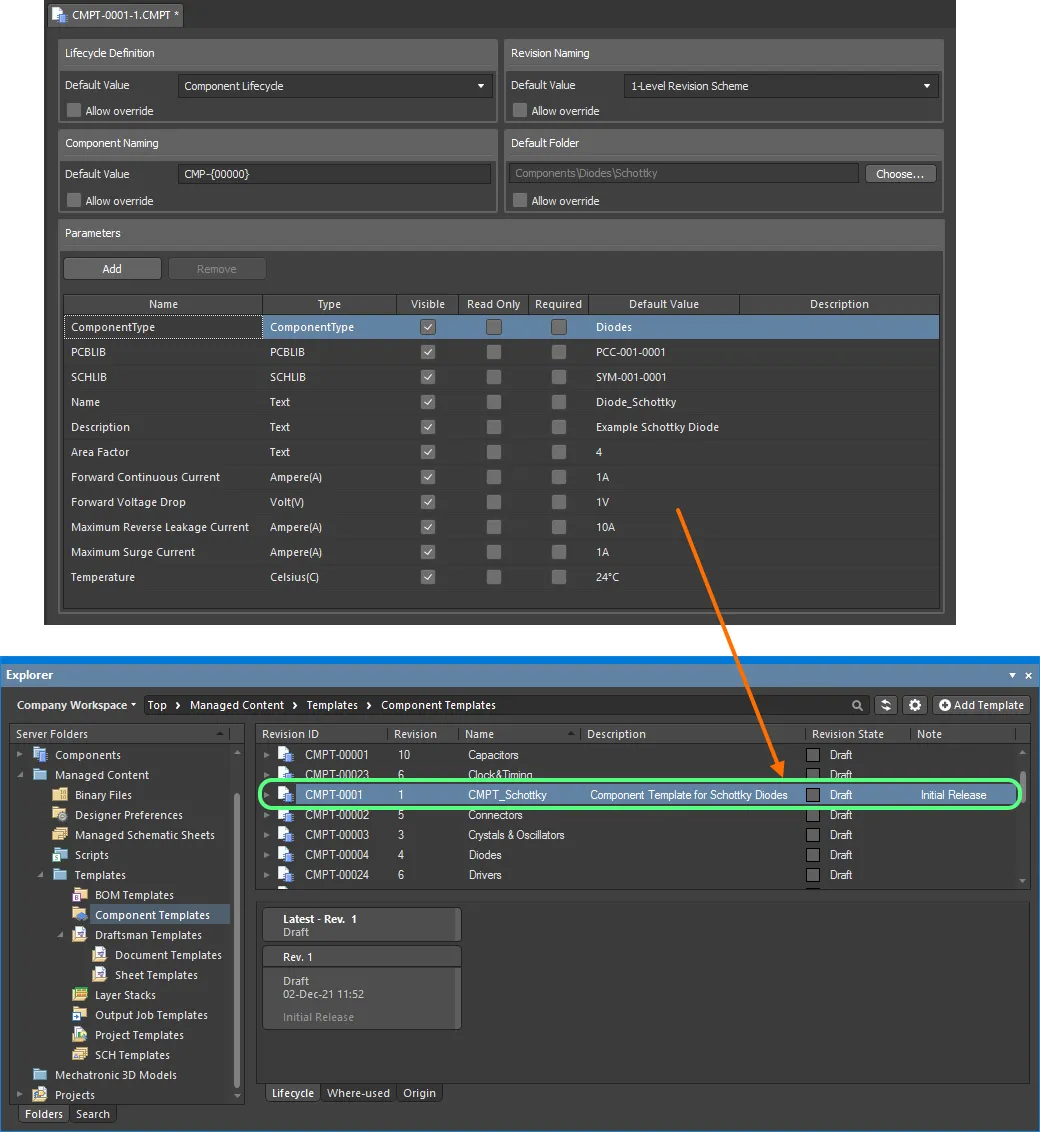
Example defined component template, saved back into the Workspace.
The CMPT (Component Template) Editor
A component template itself is defined using the Component Template Editor. This is a temporary editor delivered through a purpose-made extension – the Component Template Editor extension.
The Component Template Editor extension.
The Component Template Editor can only be accessed, provided the
Component Template Editor extension is installed as part of your Altium Designer installation. This extension is installed by default when installing the software, but in case of inadvertent uninstall, can be found back on the
Purchased tab of the
Extensions & Updates page (click on the current user control (e.g.

) at the top-right of the design space and choose
Extensions and Updates from the menu).
Defining the Template
The Component Template Editor is essentially divided into two main regions, illustrated in the following image and summarized thereafter.

The Component Template Editor can be coarsely divided into two key regions.
- Upper Region – for defining component-level options (lifecycle, naming, and folder options) for a component that references the template.
- Lower Region – for defining the parameters to be used for a component that references the template.
Specifying Component Options
The top half of the editor is dedicated to defining default values for the following component properties:
- Lifecycle Definition – choose the lifecycle definition to be applied for a component created using the template. The drop-down field lists all definitions defined for the Workspace, and which are permitted for use by a component.
- Revision Naming – choose the revision naming scheme to be applied for a component created using the template. The drop-down field lists all schemes defined for the Workspace, and which are permitted for use by a component.
If the option to control the use of lifecycle definitions and revision naming schemes per content type is enabled for any definitions/schemes, and the Component content type is not set to use a particular definition/scheme, then that definition/scheme will not be available in the applicable drop-down list.
- Component Naming – use this field to define a default Item Naming Scheme for a component created using the template, ensuring a unique ID for the resulting component in the Workspace. The entry here will be used as the template for automatically naming the component (in its associated Id field (when using the Component Editor in its Single Component Editing mode), or Item ID field (when using the Component Editor in its Batch Component Editing mode)). The software will automatically assign the next available unique ID, based on that scheme, having scanned the entire Workspace and identifiers of existing content. A default Item naming scheme –
CMP-{00000} – is provided but you can, of course, create your own scheme by typing it within the field, ensuring that the variable portion is enclosed in curly braces (e.g. CMP-001-{0000}).
- Default Folder – to specify a default folder within the target Workspace in which to store a saved component. Do this by clicking the Choose button to access the Choose Folder dialog (an incarnation of the Explorer panel) from where you can browse to, and choose, an existing folder in the Workspace, or create a new one on-the-fly.
There is no field to set the target Workspace, as this will be hard-coded to use the same Workspace as that in which the revision of the component template resides.
The
Allow override option for each property can be used to independently control whether that property can be changed (enabled) or not (disabled) by the user, when defining a component in the Component Editor. Note that this only applies to use of the editor in its
Batch Component Editing mode, where the properties are defined in the
Document Options dialog, and are the defaults applied to each new component definition added. After application, the target folder and ID of a component can be freely changed on-the-fly as required.
When the template is referenced, the entries specified in this region are used to pre-fill the applicable fields within the Component Editor (where available):
- Single Component Editing mode – the Id and Folder fields, in the Advanced Settings area of the Component region.
- Batch Component Editing mode – on the Document Options tab of the Document Options dialog and consequently the Item ID and FolderPath fields, in the Component area of the component definitions region.

When the template is referenced, the entries are used to pre-fill the applicable fields when editing a component in the Component Editor in Single Component Editing mode (left) and Batch Component Editing mode (right).
Defining Parameters
The lower half of the editor is dedicated to defining and managing the parameters that will be made available to a referencing component.
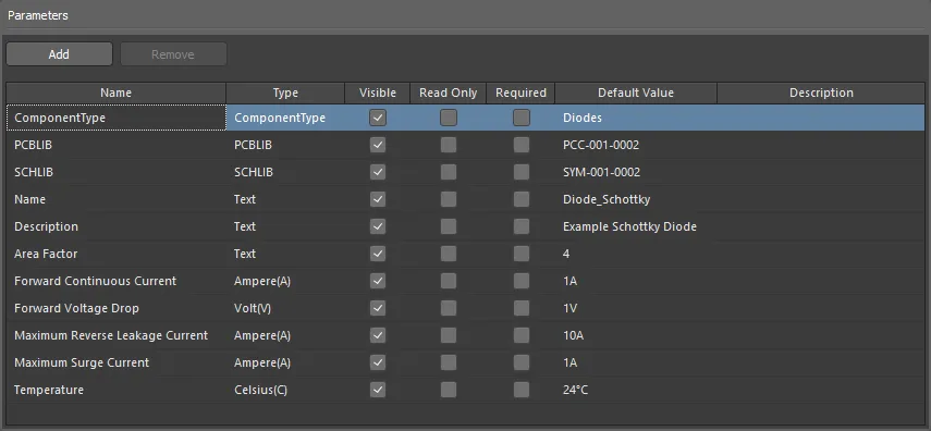
Example parameters defined in a component template.
Default System Parameters
Various system parameters are included by default when creating a new component template, as illustrated in the following image and detailed thereafter.

Default system-level parameters included in a newly-created component template.
-
ComponentType – this parameter allows you to specify the type of component. This facilitates targeted searching through the Workspace's powerful Search facility – a facility that not only allows you to search by component type but allows you to search smarter, with supported unit-aware component parameters. When browsing your own Workspace components using the Components panel, the Categories grouping for components is derived from the ComponentType parameters associated with each component. Click on the associated Default Value field, and then click the  button to access the Choose component type dialog. Use this to select the required type of component and click OK – the chosen type will be inserted as the value for the ComponentType parameter, back in the main parameters grid.
The
Choose component type dialog reflects the set of component types defined on the
Data Management – Component Types page of the
Preferences dialog. Click the

button at the bottom of the
Choose component type dialog to access this preferences page, from where you can craft this listing to better suit your needs – either by adding new types and sub-types, or editing and removing existing types.
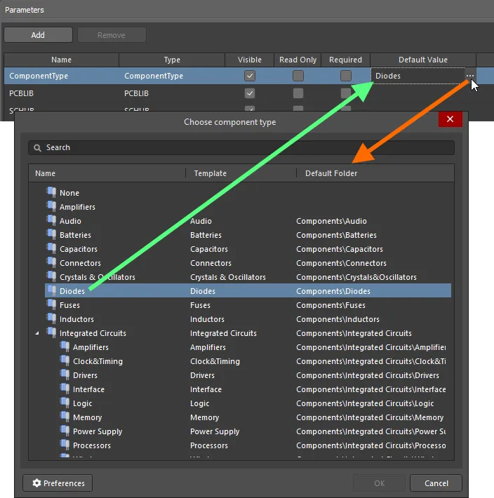
Example Component Template, with the ComponentType system parameter set to Diodes.
The data type for this parameter is set to ComponentType, and cannot be modified. Also, the ComponentType parameter cannot be copied or removed. Select the cell and use the Delete key to clear the value.
-
SCHLIB and PCBLIB – these two parameters allow you to specify default symbol and footprint models, respectively. Click on the associated Default Value field for each parameter, and then click the  button to access a dialog with which to choose the required model.
Note that it is the model that you are choosing, and not a specific revision of that model. In this way, a component using the template will always use the latest revision of the chosen model.

Specify symbol and footprint models as part of your template.
The data types for these parameters are set to SCHLIB and PCBLIB respectively, and cannot be modified. Also, the model parameters cannot be copied or removed. Select the cell and use the Delete key to clear the value.
-
Name and Description – these two parameters allow you to define the name and description for the component respectively. Enter the required strings in the associated Default Value field for each parameter.

Specify Name and Description parameters as part of your template.
The data type for both of these parameters is set to Text and cannot be modified. Also, these parameters cannot be copied or removed.
Adding a New User Parameter
To add a new user parameter to the list, click the  button (or use the Add command from the right-click context menu) – the parameter is added to the bottom of the current list.

Example addition of a new user parameter to the template.
Each parameter is presented in the grid listing in terms of the following information:
- Name – use this field to name the parameter, typically a meaningful name that conveys its purpose. When initially added, parameters will be given default names (
Parameter, Parameter 1, Parameter 2, and so on).
- Type – the type of parameter. This entry will default to
Text initially, but a range of unit-aware data types are supported, as well as the type PCBLIB, which facilitates the definition of multiple footprints.
- Visible – enable this option (which is the default state for a newly added parameter) to have the corresponding Show option for the parameter enabled when editing one or more components in the Component Editor (configured in Batch Component Editing mode). This, in turn, controls the display of the corresponding column for that parameter in the lower region of the Component Editor, where the component definitions themselves are defined. This property has no effect when defining a component using the editor's Single Component Editing mode.
- Read Only – enable this option to make the parameter read-only. When editing a component that references the template, the value for the parameter will be made non-editable.
- Required – enable this option to make the parameter a 'required parameter'. When editing a component that references the template, the parameter must have a value defined for it, otherwise, saving of the component will not be possible. In the Component Editor, such a parameter is distinguished by the value cell having a red border (in Batch Component Editing mode) or containing the
 icon (in Single Component Editing mode), when no value has been entered.
-
Default Value – use this field to enter a default value for the parameter.
If the parameter is marked as being required (Required option enabled) and has also been set to be read-only (Read Only option enabled), then a default value MUST be entered. If not, when editing a component that references the template, the parameter will be flagged as not having a value, but this cannot be resolved because the parameter is non-editable because it is read-only. A new revision of this component template can not be Saved to the Server until this is resolved.
- Description – add any description for the parameter, for example, a concise note about what it provides. If a parameter in the template has a description defined for it, then the Description column will be presented in the Parameters region of the Component Editor in its Single Component Editing accordingly.
The parameters list also supports simple copy and paste actions, allowing you to duplicate one or more existing user parameters. The pasted parameter(s) will be added to the bottom of the list.
Standard copy (Ctrl+C) and paste (Ctrl+V) shortcuts are supported, and these commands are also available from the right-click menu. Multiple user parameters can be selected for copy-paste operations, using standard Ctrl+Click and Shift+Click techniques.
To delete one or more user parameters from the list, select each parameter, then click the

button, or use the
Remove command from the right-click context menu.
Column Ordering and Sizing
The order of the columns is customizable. Click on a column's header and drag it horizontally to the required new position. Valid positions are highlighted by vertical positional arrows.
The width of a column can be modified by clicking and dragging the right-hand separator (in that column's header).
Sorting
Parameters can be sorted by a specific column by clicking on that column's header. Click once to sort in ascending order (based on the content of that column). Click again to sort in descending order.
You can sort by multiple columns. With the parameters already sorted by a specific column, Shift+Click on another column to 'sub-sort' by the content of that column.
To remove sorting for a column, Ctrl+Click on its header.
Unit-Aware Component Parameter Data Types
The Component Template Editor provides the ability to define explicit data types for component parameters defined within a component template (*.CMPT). In addition, these data types are unit-aware, with a range of popular unit prefixes supported. As such, you can enter a parameter's value using a range of formats – such as 2.2k, 2k2, 4M, 2.5GHz – with the Workspace engineered with the requisite smarts to recognize the numerical value behind those entries.
This feature of a component template facilitates targeted searching through the server's Advanced Search facility – a facility that not only allows you to search by component type but allows you to search smarter, with range searches. Using the power of unit-aware component parameters, you can quickly define a search, for example, to find all capacitors with a capacitance between 47uF and 220uF.
Unit-aware parameters are also used for smart filtering when searching through your own components using the
Components panel.
Use the following collapsible sections to learn more about unit-aware parameters.
Supported Units
The following unit-aware data types are supported when defining a user parameter as part of a component template:
Most data types have a unit (in brackets). This will be applied if no unit is specified when entering a value for a parameter.
- Volt(V)
- Ampere(A)
- Ohm
- Farad(F)
- Henry(H)
- Watts(W)
- Hertz(Hz)
- Celsius(C)
- Decibel(dB)
- Percent(%)
- Metre(m)
- Gram(g)
- Second(s)
Supported Prefixes
The following table lists prefixes that are supported when entering a value for a unit-aware parameter type.
| Prefix |
Term |
Value (Scientific) |
Value (Normal) |
| T |
Tera |
1 x 10¹² |
1,000,000,000,000 |
| G |
Giga |
1 x 10⁹ |
1,000,000,000 |
| M |
Mega |
1 x 10⁶ |
1,000,000 |
| k |
kilo |
1 x 10³ |
1,000 |
| m |
milli |
1 x 10⁻³ |
1 / 1,000 |
| u |
micro |
1 x 10⁻⁶ |
1 / 1,000,000 |
| n |
nano |
1 x 10⁻⁹ |
1 / 1,000,000,000 |
| p |
pico |
1 x 10-12 |
1 / 1,000,000,000,000 |
| f |
femto |
1 x 10-15 |
1 / 1,000,000,000,000,000 |
Note that the use of some, or all prefixes may not be applicable, depending on the parameter type. For example, no prefix is valid for a Percentage. The software will alert you to any invalid use of prefixes.
Adding a Unit-aware Component Parameter
When adding a parameter to the template (click  in the Parameters region), use the associated Type field to choose the required unit-aware data type from the drop-down.
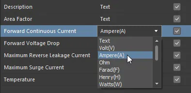
Choosing a supported unit-aware data type for a user parameter in a component template. In this example, Ampere is the parameter type.
When entering a value for a component parameter that uses a unit-aware data type – either as the Default Value in a component template or as the required value in a component definition – the following are things to consider:
- You can enter the value in a range of different formats:
- Numerical value only (e.g.
10). Note that if the data type has a unit, this will be applied automatically. Those types with units have the unit in brackets after their name.
- Numerical value in scientific notation (e.g.
1e10, 1E6).
- Numerical value and units (e.g.
10F).
- Numerical value with prefix (e.g.
10k). The appropriate unit will automatically be added (where applicable).
- Numerical value with prefix and units (e.g.
10kF).
- Numerical value with prefix in typical engineering format (e.g. for a resistance:
2k2, 2K2, 10r2, 10R2). The value will automatically be normalized accordingly (e.g. 2K2 will become 2.2k).
- You can enter prefix and/or units with or without a space after the numerical value (e.g.
10uF, or 10 uF). The space will be automatically stripped.
Note that engineering abbreviations are case insensitive, so entering 2k2 is the same as entering 2K2, and entering 100R is the same as entering 100r. The only exception is M (Mega) and m (milli).
Data Validation
When a unit-aware data type is used for a component parameter, the entered value is validated against the specified data type. This ensures that the correct measurement unit for that data type is used. For example, a parameter of type Celsius cannot have a value of 10V!
Validation is performed wherever a component parameter with a unit-aware data type is used and a value for that parameter is supplied:
- When defining a default value for a parameter in a component template.
- When defining a value for a parameter as part of a component's definition in the Component Editor.
- When configuring a range search, based on parameter value, as part of a saved search scheme.

Example of data validation in action within the Component Template Editor.
Defining Multiple Footprints
The Component Template Editor also provides support for defining multiple PCB footprints as part of a component template. Any number of footprint model links may be specified, and this will be a welcome feature for those wishing to create components that reference 3 footprints, satisfying the IPC requirements for different density levels: L (least, or minimum copper), M (most, or maximum copper), and N (nominal, or median copper).
To add an additional footprint model definition to the template, click  to add a new parameter, then choose the
 PCBLIB entry on the drop-down menu associated with the Type field.

Turn a newly added parameter into a footprint model definition by setting its Type to PCBLIB.
The name of the parameter will change from
Parameter to
PCBLIB n, where
n is the next available integer to distinguish between multiple footprint models (e.g.
PCBLIB 1,
PCBLIB 2, and so on). The default model will be the one associated to the
PCBLIB entry. When the Footprints are brought into the Component Editor, when defining a component, the default Footprint model is distinguished by the

icon at the top-left of the model preview window (when in
Single Component Editing mode), and by the entry
PCBLIB (default) in the
Required Models/Parameters region (when in
Batch Component Editing mode).
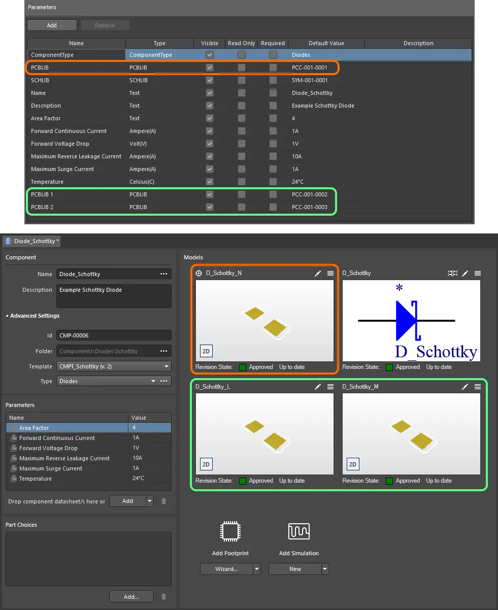
An example component defined in the Component Editor (Single Component Editing mode), using a referenced Component Template. The template has three footprint models defined, which are brought into the component definition. Notice that the PCBLIB model entry in the template is used as the default footprint model (distinguished by an icon at its upper-left) when defining the component. Hover over the image to see the same component being defined with the Component Editor in Batch Component Editing mode. In this case, the default footprint is termed PCBLIB (default).
Component Template Import and Export
An existing component template file (*.CMPT) or component library file (*.CMPLIB) can be imported to the component template editor, and the component template being edited can be exported to a component template file (*.CMPT). Use the File » Import » Component Template, File » Import » Component Library and File » Export commands of the component editor's main menu to select the desired action and the standard Windows dialog that opens to browse to the required location and select a file to import or define the name of the file that will be exported.
Reusing a Component Template
Using a revision of a component template – or rather referencing one from the revision of a component you are currently editing – can be performed in the following ways.
A component can only reference one component template at a time.
When Creating a New Component
When creating a new component using the File » New » Component command from the main menus, you can choose the template in the Create new component dialog.

Quickly linking a component template from a listing of all available templates, when creating a new component.
Manually from within the Component Editor
Reusing a revision of a component template from the Component Editor depends on the operating mode of the Editor.
In Single Component Editing Mode
When editing a single component in this mode of the Component Editor, choose the required Component Template from the drop-down menu associated with the Template field – part of the Advanced Settings grouping, in the Component region of the Editor. All component template currently available in the same Workspace in which the component itself resides are listed – by name – with their latest revisions indicated in brackets. Choose the required template to have it applied.
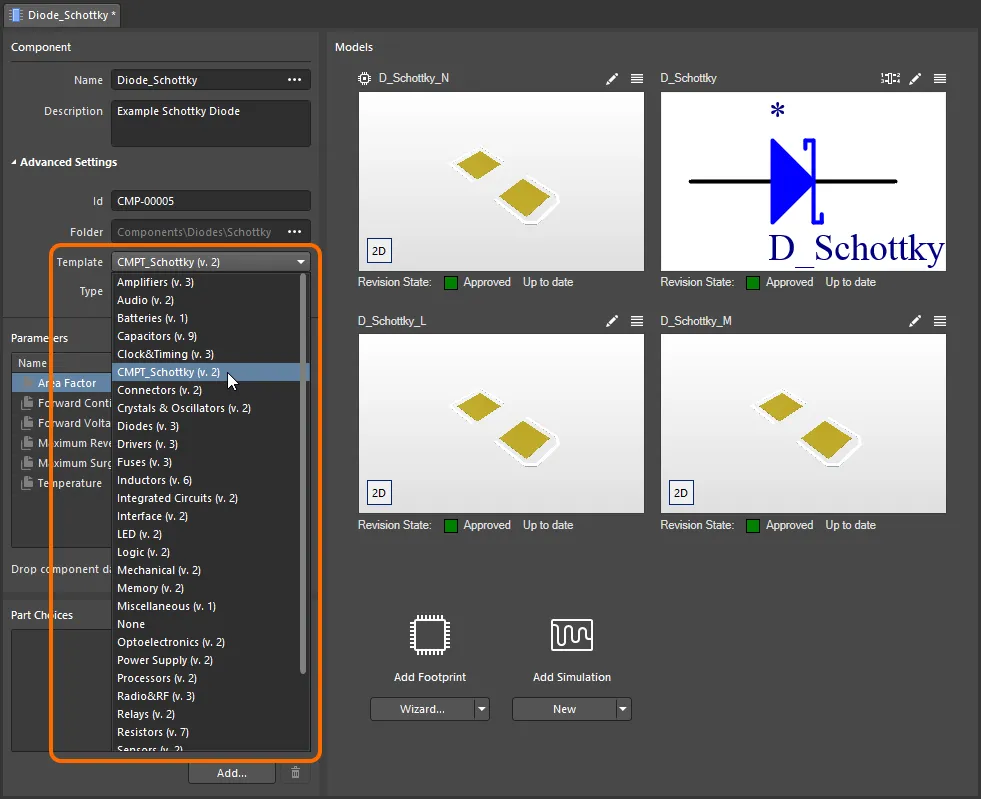
Quickly linking a component template from a menu of all available templates, when editing the revision of a component using the Component Editor in its Single Component Editing mode.
In Batch Component Editing Mode
There are two ways of 'hooking up' a revision of a Component Template, to the component revision currently being edited:
-
From the Template tab of the Document Options dialog (Edit » Document Options). Click the Choose button to the right of the Item Revision field. This gives access to the Choose Item dialog (an incarnation of the Explorer panel). Use this dialog to browse to, and select the revision of the required component template. After clicking OK, a link will be created between the revision of the component and the target revision of the component template. Evidence of this link can be seen back on the Template tab of the Document Options dialog.

Manually linking a component to a revision of a component template, in the target Workspace.
The component template being used can be changed at any time – click Choose and select a revision of a different component template.
The status of the linked Component Template Item Revision is reflected on the
Template tab of the
Document Options dialog. If a newer revision of the linked Item is available, click the

button to use that latest revision.
-
From the Add menu associated with the Required Models/Parameters region of the Component Editor. The Templates sub-menu lists all component templates – by name – currently available in the same Workspace in which the component itself resides, with their latest revisions indicated in brackets. Click on an entry to create a link to the latest revision of that component template. Once again, verification of the link can be seen on the Templates tab of the Document Options dialog.
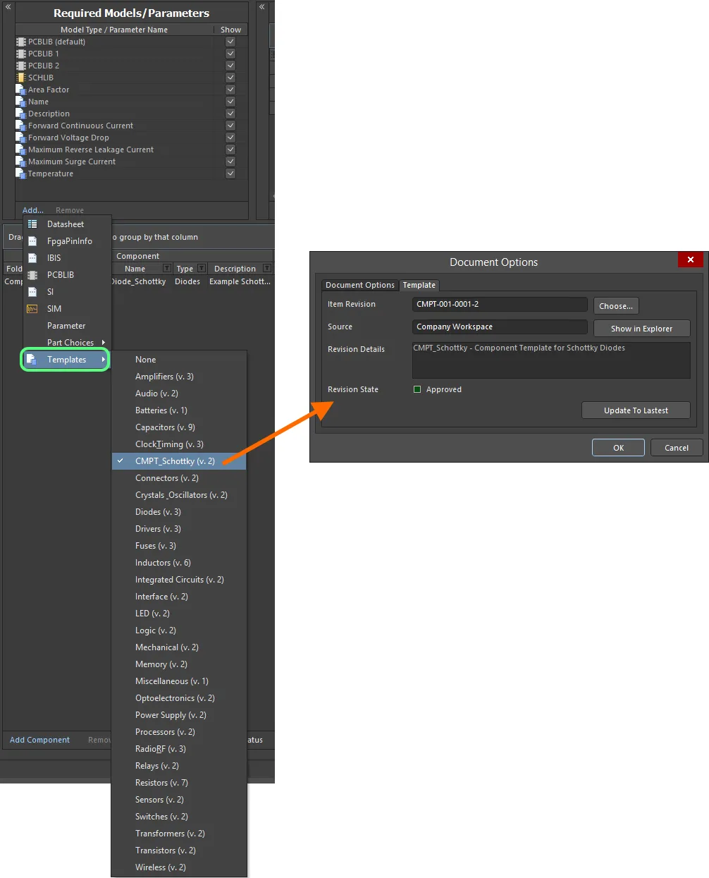
Quickly linking a component template from a menu of all available templates.
Inherited from the Components Workspace Folder
You can specify a component template to be automatically used for all components (and revisions thereof) stored within a Components folder within the Workspace.
A default component template can only be defined for a folder of type Components.
Specify the required template using the Component Template field, when defining the folder's properties, in the Edit Folder dialog. The field's associated drop-down lists all component templates – by name – currently available in the same Workspace in which the Components folder itself resides, with their latest revisions indicated in brackets. Choose an entry to create a link to the latest revision of that component template, for each subsequent component created within that folder.
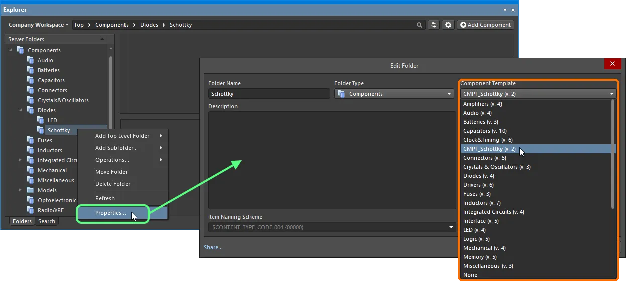
Specify a default component template, to be applied to all components created within the parent Components folder.
To not use this feature, leave/set the Component Template field to None.
If a Component Template is chosen at the folder level, that same template will be used, by default, when components are created in child sub-folders below. This facilitates quick template inheritance to all components in child folders.
When a revision of a component is saved to the Workspace, it will essentially lock-in the specific revision of the Component Template used – creating a strong link to that revision, unless changed manually.
Impact on Component Models and Parameters when using a Component Template
When editing a revision of a component, and a revision of a component template is linked to/referenced, the following happens within the Component Editor, with respect to models and parameters:
- The models defined within the referenced template are added to the Models region (Single Component Editing mode) and Model Links region (Batch Component Editing mode).
- An existing referenced model will be kept, and the component will remain using that model unless purposefully changed manually.
-
The parameters defined within the referenced template are added to the Parameters region (Single Component Editing mode) and Required Models/Parameters region (Batch Component Editing mode).

Example of parameters after linking to a revision of a component template, when using the Component Editor in Single Component Editing mode (left) and Batch Component Editing mode (right).
All parameters originating from the referenced component template are distinguished by use of the

icon (
Single Component Editing mode) and

icon (
Batch Component Editing mode). In addition, and for Batch Component Editing mode only, the
Show option for each template-based parameter follows the state of the corresponding
Visible option in the template.
Template-based parameters cannot be removed.
You are free to add additional user-parameters as required.
- An existing user-defined parameter that has the same name as a parameter in the linked component template, will be replaced with the template version. Any existing value for that parameter will be kept (and not overwritten with the value in the template).
-
In Batch Component Editing mode only, template-based parameters that are set to be shown are grouped together in the component definitions area of the editor, with Template Parameters used as the header text.

Appearance of example template-based parameters in the area where the component definitions themselves are defined, when using the Component Editor in its Batch Component Editing mode.
-
The value fields for template-based parameters that have been marked as read-only, will be non-editable. For all other template-based parameters, that have not been marked as read-only, you are free to change the values as required.
With the Component Editor in
Single Component Editing mode, a Read-only template parameter is distinguished in the
Parameters region by use of the

icon.
-
If a template-based parameter has been marked as required but has not been given a value in the template, its value field will appear with a red border (in Batch Component Editing mode) or containing the  icon (in Single Component Editing mode), alerting you to the fact that a value is required for this parameter. You will not be able to save a component to the Workspace until values are defined for all required parameters.
With the Component Editor in
Single Component Editing mode, a required template parameter is distinguished in the
Parameters region by use of the

icon.
Re-Saving a Component Template
At any stage, you can come back to any revision of a component template in the Workspace, and edit it directly. Right-click on the revision and choose the Edit command from the context menu. Once again, the temporary editor will open, with the template contained in the revision opened for editing. Make changes as required, then save the component template into the next revision of the Item.
Right-clicking on the top-level entry for a component template itself, will edit the latest revision of that template.
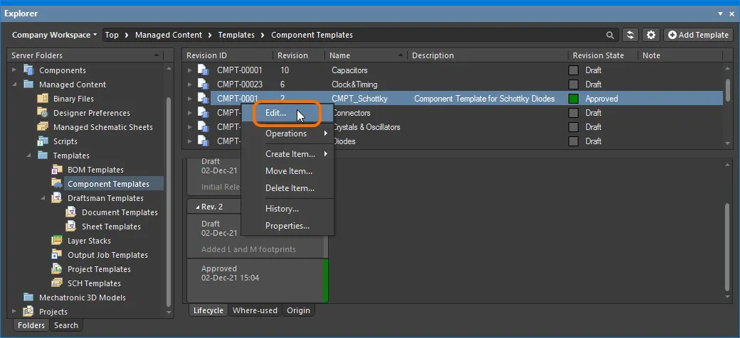
Accessing the command to launch direct editing of an existing revision of a component template.
Downloading Saved Data
Download the data stored in a revision of a component template by right-clicking on that revision (in the Explorer panel) and choosing the Operations » Download command from the context menu. The component template file will be downloaded into a sub-folder under the chosen directory, named using the Item Revision ID. The file can be found in the Released folder therein.
Access the Download command from the top-level entry for a component template itself, to download the component template file stored in the latest revision of that template.
Click the Explore button in the Download from Server dialog, to quickly explore to the download folder.
Soft Deletion
When connected to a Workspace, flexible functionality is available for removing a component template directly from within Altium Designer, from the Explorer panel. Right-click on the component template's entry in the panel and choose the Delete Item command from the context menu. The Delete Items dialog will appear, in which to confirm the deletion. The action is actually a 'soft delete', whereby the component template will be moved into the Trash area of the Workspace. The Trash is essentially a recycle bin into which any content within your Workspace can be moved (through a soft delete action). It is isolated from the rest of the Workspace.
With the soft-delete facility, you are able to delete a component template that is currently being used.
Multiple component templates can be deleted in a single action. Select all required component templates using standard multi-select controls (Shift+Click, Ctrl+Click), then right-click and choose the Delete Items command from the context menu.

Soft deletion of a component template. The template will be moved to the Workspace's Trash area.
To proceed with the deletion, click the  button. The item will be removed and a Deletion Summary dialog will confirm successful deletion. If there was an issue with deletion, this will be flagged to you.
All content deleted in this manner can be found on the Trash page of the Workspace's browser interface. Note that you can only view content that you have personally soft deleted. Administrators will be able to see the full content of the Trash page – so all content that has been soft deleted.
Things to consider in relation to a soft deleted component template:
- The component template will not be available from your design software, or from within the Web interface.
- Anywhere the component template was being used will reflect that the component template has been deleted.
- A component template can be restored, or permanently deleted from the Trash page, provided you have editing rights. Permanent deletion is only possible provided it is not being used by a parent Item.
Note that if you have soft deleted a component template – moving it to the Trash – you can create a new component template with that same name again. If you were to subsequently restore the original component template, and the original name is taken, an integer suffix will be used, to keep its name unique within the Workspace.