Draftsman provides an advanced, yet flexible graphical editing environment for creating board design production documents. Based on a dedicated file format and set of drawing tools, the Draftsman drawing system provides an interactive approach to bringing together fabrication and assembly drawings with custom templates, annotations, dimensions, callouts, and notes.
Do I have Draftsman installed?
The Draftsman PCB drawing capabilities are available through an Altium NEXUS Extension application, which is automatically installed with Altium NEXUS. The extension can be manually installed/removed or updated from the Altium NEXUS Extensions & Updates page (select the Extensions and Updates option from the system User menu –  ). The Draftsman extension is located within the Installed tab and within the Updates tab when a software update is available.

► See Extending Altium Design Software for more information on installing and managing Altium software Extensions.
Key Features
The Draftsman drawing application can act as an adjunct, or even an alternative, to the production of graphical-type PCB production documents using traditional outputs. It offers automated placement of assembly and fabrication drawings on demand, and includes a wide range of manual drawing tools that can be used to add important details and highlighting to its multi-page documents.
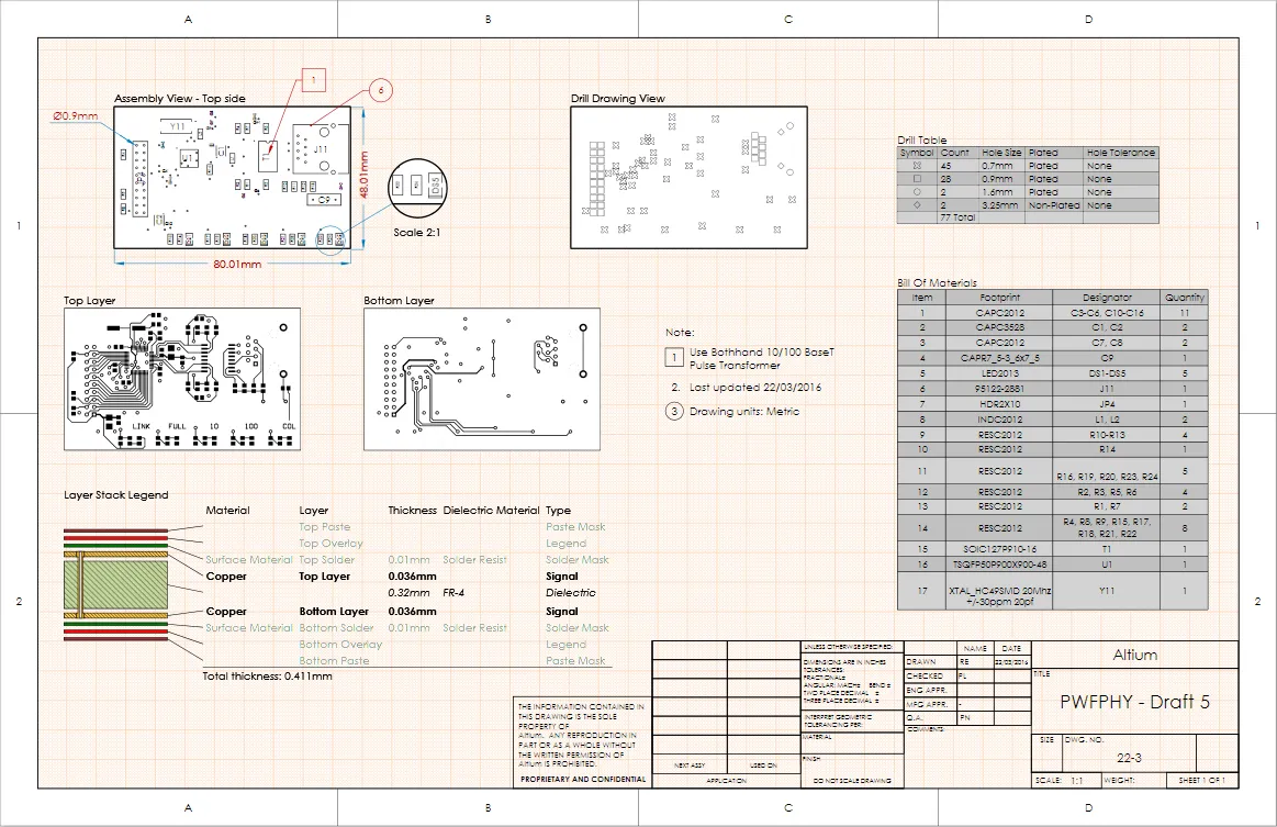
Place drawing views, objects and automated annotations on single or multi-page Draftsman documents.
Draftsman's key features include:
- Automated extraction of drawing data from the source PCB document.
- Creation of multi-page documents.
- The application of separate templates to each page of a document.
- Automatic generation of drawings from customized templates.
- Broad range of drawing views (Assembly View, Fabrication View, Section View, Drill Drawing View, Board Region View, etc).
- Assembly Views that include graphics generated from 3D Models (without the requirement for special PCB layers).
- A customizable Layer Stack Legend with the option to add detailed layer information.
- A BOM table that integrates with ActiveBOM to show all board items or only those items for a selected Assembly View.
- Placement of Callouts to indicate BOM item positions or items from a Notes list.
- Support of assembly Variants.
- User preference settings for drawing objects and functions (accessed via the system
 button).
- Print and Export to PDF outputs.
- Inclusion in OutJobs, where a Draftsman PCB Drawing file can be added as a new Documentation Output.
- ...and much more.
Working with Documents and Templates
The Altium Draftsman application creates and saves PCB drawing files (*.PCBDwf) and uses specific template formats for defining Sheet (page) properties (*.DwsDot) and Document content (*.DwfDot). The 'smart' document templates can be configured to automatically populate the document with nominated PCB drawing views and information text. When initially created, Document templates can use current Sheet templates to define the page properties (size, style, margins, etc.).
Create a New Document
A new Draftsman document is created in Altium NEXUS using the File » New » Draftsman Document command. The New Document dialog opens.
The dialog allows for the selection of a predefined Document Template or a Default option that creates a blank A4 document – note that a Sheet Template can be applied once the new document has been created.

Create a blank or template-based Draftsman document from a specified project and PCB.
The list of available templates:
- When you are signed in to a Managed Content Server - the
\Managed Content\Templates\Draftsman Templates\Document Templates\ folder in the Managed Content Server.
- Not currently signed in to a Managed Content Server - the default Templates location defined in the Draftsman - Templates page of the Preferences dialog, click the
 button to configure the location of file-based templates.
Along with the desired Draftsman template, a specific Project and board Source Document can be selected where multiple files are open in Altium NEXUS. The new document will be associated with, and therefore draw data from, the nominated project, which will become the active project. The newly created document will be added to the nominated project.
The dialog's Layers checkboxes determine which board layers (as defined by the Layer Stack) are used to generate Fabrication drawings in the document (at one per sheet) when a Fabrication document template is used.
Document Sheets
Draftsman files are a multi-sheet format, which allows documents to contain individual pages (sheets) that are assigned to particular types of board project production information. Sheets can be added to and removed from the current document with the Tools » Add Sheet and Tools » Remove Sheet commands (the commands are also available on the right-click context menu).
The currently active sheet number and the total number of sheets in a document are shown in the Status bar at the bottom of the workspace.

Page Options
The settings for individual pages (sheets) in a Draftsman document can be defined in the Properties panel, under the Page Options tab.
Open the Properties panel from the system  button, or select View » Panels » Properties from the main menu. The panel’s Document Options mode is active when no object is selected in the workspace.
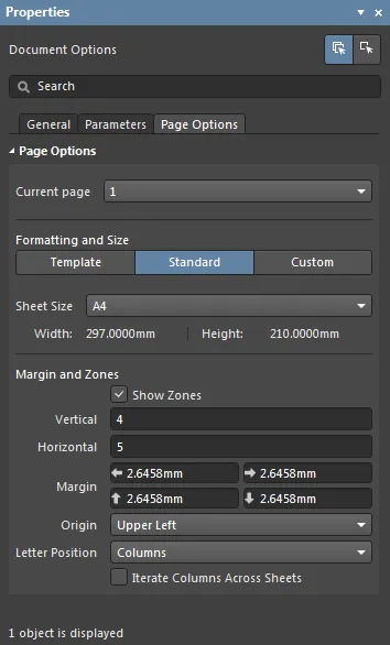
The settings under the Page Options tab determine the base structure (size, margins, etc.) of the current page or all pages in the document. Alternatively, the page format can be defined as a custom size, or by loading a sheet Template document.
Changes made to the Page Options properties can be applied to the current page ( ), or all pages in the document (
 ). For settings that apply to the overall Draftsman document and its constituent pages, see Document Options below.
► See the Properties panel Page Options section for more information.
Create Templates
An Altium Draftsman document can use templates to define its page properties (Sheet template), and for new documents, a range of predetermined content (Document template). Both types of templates can be created from the PCB drawing file (file extension PCBDwf) that is currently open in the editor by saving the document as one of the template types (DwsDot or DwfDot). A Template document may be reopened, edited and saved to modify its content and properties.
Sheet Template
Sheet (page) templates contain the graphics information for a page, including sheet sizes, parameters, and zones and border settings. Objects created with the editor's graphics tools (such as lines, rectangles, circles, and text) are also included – for example, a constructed Title block and content.
If using an automated sheet numeration
parameter in a Title block, note that two System types are supported for documents: the conventional
SheetNumber parameter and the
GOST compliant
SheetNumber_OneSheet parameter. The latter will not report the current sheet number when only one sheet exists in the Draftsman document (as per the
GOST 2.104-2006 drawing standard), and will otherwise deliver the same numbering as the
SheetNumber parameter.
A Sheet Template can be used to define the graphic format of a new or existing drawing document, and are also saved as part of a Document Template.
To save the current drawing document format as a Sheet Template, select the File » Save Copy As (or just Save As) command and choose Altium Draftsman Sheet Templates (*.DwsDot) from the Save dialog's Save as type selection filter. Any elements that are incompatible with the Sheet Template format will be removed, such as placed drawings or additional pages. Before saving, an alert dialog will detail the pending action if incompatible elements exist.
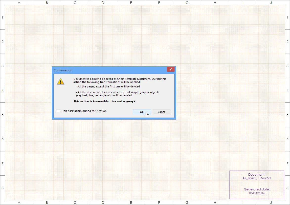
As with other Altium NEXUS documents (Schematic, PCB, etc.), the Save As command will replace the existing source file in the project structure (in this case, a Draftsman drawing document) with the newly saved file (a Sheet Template document). The source document (*.PCBDwf) is not deleted from the project folder on disk.
A better approach is to use the Save Copy As option, which will save the new template to the nominated directory while leaving the source document (and project contents) intact.
Note that a saved Sheet Template can be applied to a Draftsman document page from the Properties panel Template section under the Page Options tab. Select the  option then select a template from the dropdown. Alternatively, click the
  button to locate and load a specific Sheet Template.
Document Template
Document Templates define a Draftsman document's content and (optionally) its style properties. The template supports multi-page documents, data for the main document attributes (tables and lists, drawing types, etc.), and elements created by the drawing Editor that do not depend on the PCB's design content.
To save the current drawing document format as a Document Template, select the File » Save Copy As (or just Save As) command and choose Altium Draftsman Document Templates (*.DwfDot) from the Save dialog's Save as type selection filter. All of an existing drawing document's content and attributes, with the exception to those that relate to data extracted from the PCB design, will be saved as a Document Template. If the source drawing document has a specific page style (as might be applied by a Sheet Template) these graphical elements and attributes will be saved with the new Document Template.
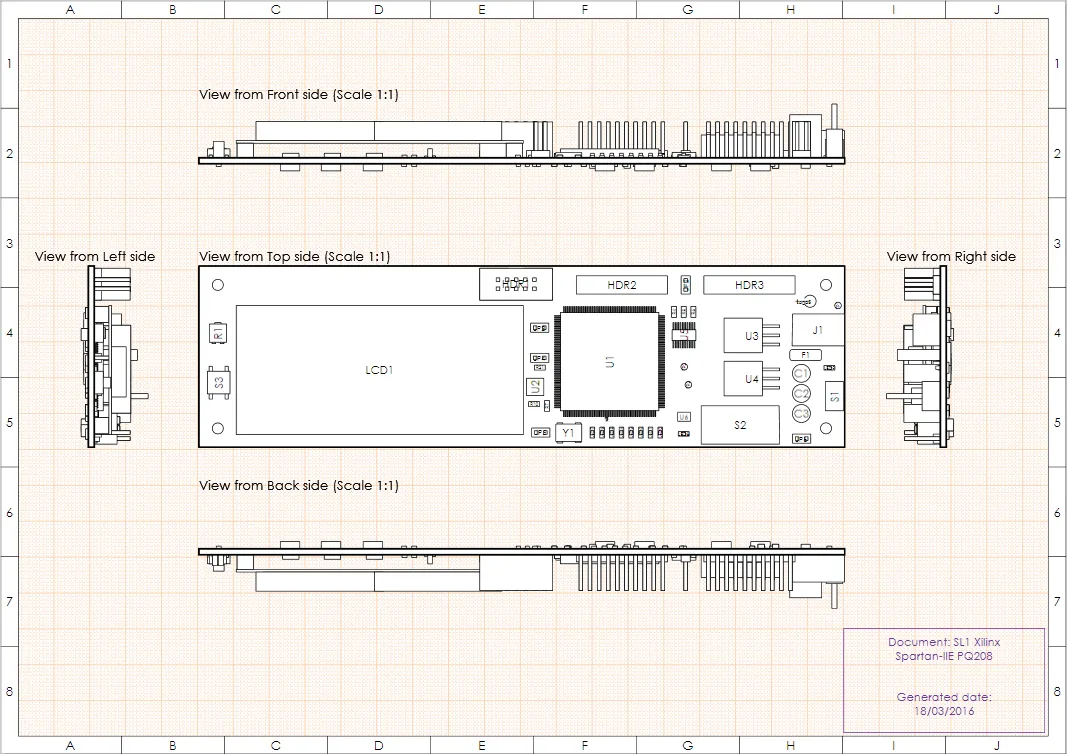
Any elements that are incompatible with the Document Template format will be removed. Before saving, an alert dialog will detail the pending action if incompatible elements exist.

A multi-page Draftsman document might typically contain assembly drawings, drill tables and drawings, layer stack and BOM tables, and fabrication drawings. When saved as a Document Template, the data from the current PCB is retained to define a drawing content 'shell'.
When subsequently used as a template for a new drawing document, the project's current PCB data is loaded into the shell in place of the template PCB data, therefore, recreating the document format and its type of content.
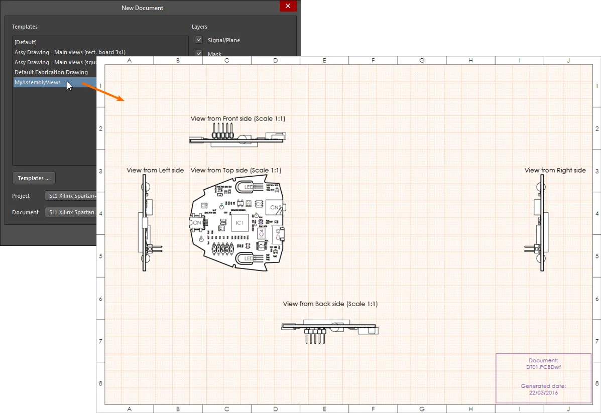
For a custom Document Template to be available in the Templates area of the New Document dialog it must have been saved in Draftsman’s registered Templates Location. The location path can be viewed, or changed, in the Draftsman Templates page of the Preferences dialog.
Edit a Template
Both Sheet and Document templates can be opened as free documents in Altium NEXUS and edited accordingly. Open a template by selecting File » Open and choose Altium Draftsman Sheet Templates (*.DwsDot) or Altium Draftsman Document Templates (*.DwfDot) from the browser filter options.
An open Document Template will include the PCB design data that applied when the template was created, and also the Sheet Template properties that were active when it was created. If a Sheet Template defined the page properties in that Document template, it will need to be reapplied if the Sheet Template has changed in the interim.
Document Options
The settings for the overall Draftsman document (potentially composed of multiple sheets/pages) are defined in the Properties panel, under the General tab.
If not already active, open the Properties panel from the system  button, or select View » Panels » Properties from the main menu. The panel’s Document Options mode is active when no object is selected in the workspace.
 The Draftsman Document Options apply to all pages of a drawing document.
The Document Options settings determine the document’s source design data, graphic styling, drawing behavior, and the applied units. Changes to the settings override the panel’s default property settings, which are defined by current document template – such as the default template (Default.PCBDwf).
Metric Unit Precision
If the document units are set to metric (Millimeters) in the Units section of the Properties panel Document Options (under the General tab), it is highly recommended that the associated Precision options are set to no greater than 5 decimals places – 0.00001 (1/100000).
When set to higher precision levels (such as the 0.00000000001 maximum) the numeric resolution exceeds that of the PCB Editor's base imperial unit, which can result in inaccurate measurements in Draftsman due to unit conversion rounding errors.
► See the Properties panel Document Options Mode for more information.
Note that the Document Options apply to the entire drawing document, however, the
Page Options apply to individual document pages (sheets). Both the Document Options and Sheet Properties are saved with the current Draftsman document, and/or in a saved document Template.
Working with Drawing Views
The Altium Draftsman application allows a range of automated production drawings to be placed directly onto a Draftsman drawing document.
The type of drawing to be placed is selected from the icons presented in the editor's Active Bar (located at the top of the workspace) or the Drawing Views toolbar. Alternatively, a drawing type can be placed from using Place from the main menus or by right-clicking in the workspace and selecting a Place option from the context menu.
 Draftsman's Active Bar provides access to the main drawing views and objects.
Draftsman Properties Panel
When placed in the document, drawings can be manipulated within the page and their properties edited from a dedicated Draftsman Properties panel. If not already open, the panel can be activated by double-clicking on a placed drawing view, by selecting the drawing view and choosing Properties from the right-click options menu, or by selecting the Properties option from the system  menu.
menu.
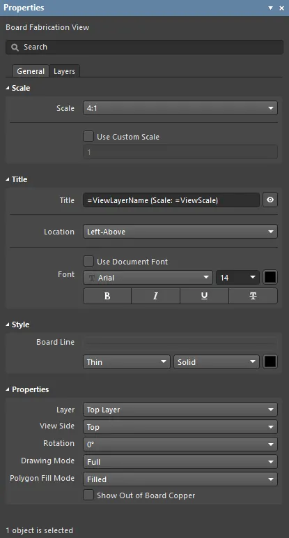
The panel automatically changes its mode and content to match the selected drawing view or object.
The panel provides editing access to the detailed properties of objects that have been placed in the drawing document. Select an object or view to see its properties in the panel.
When a drawing view is selected, press
F1 to access documentation for that object. For a selected Board Assembly View, for example, this will open the
Board Assembly View object page, which also includes a link to its detailed
Board Assembly View Properties page.
Board Assembly View
A Draftsman Board Assembly View is an automated graphic composite of the active PCB project's board outline, cutouts, holes, and component graphics with additional notation. An Assembly View for the nominated source project PCB is placed in a document by selecting the  object icon, or via the Place menu options.

A placed board Assembly View can be moved, scaled and viewed from different sides.
Components
The Board Assembly View's component graphics are automatically generated and take data on a priority basis from several sources, such as:
- The projection of a board component's three-dimensional model (3D model) – used by default.
- A component's silk screen graphic taken from the Top/Bottom Overlay layer – used when a 3D model is not available.
- A graphic of the component's dimensions derived from its contact pads (its Bounding Box) – used when both a 3D models and screen overlay are not available.
- A component graphic on the Assembly Component Layer Pair specified in the PCB design, under the Layers & Colors tab of the View Configuration panel – the layer pair containing component data is set to the
Assembly Layer Type in the associated Edit Layers dialog.
Note that the automatic generation of a Board Assembly View does not rely on the availability of an additional board assembly layer (for example, Top/Bottom Assembly), so this mode is an option.
Use the Component Display Properties section of the Properties panel to set the visibility, designator attributes and graphic style of all components shown on the Board Assembly View. Alternatively, select a specific component on the Assembly drawing itself to set only its graphic options in the Component Display Properties section.
For access to all component display attributes, including component Footprints, Classes, and any associated Parameters, select the panel's  button to open the the Component Display Properties dialog, where component properties may be changed individually, in groups or through multiple selection.
Displayed layer data
Further PCB topology information is included in a Board Assembly View by enabling layer data associated with the current view (Top or Bottom) in the Properties panel.
With a Top side assembly view, for example, the panel’s Topology option (under Show additional data) displays the board Top Layer – and enables SMD/through-hole pad options, which may be selected independently. The Mask and Paste options overlay the Top solder mask and paste layers, as determined by the current view side (Top, in this case).
Additionally, the Properties panel’s Layers tab is populated with the mechanical layers available in the board design. Multiple layers can be selected for display, where their draw order determined by the listed order. Use the  and
and  buttons to specify a layer’s relative list/draw order.

To change the color of a layer overlay on a view, select its associated color icon to open the color selector drop-down, which offers standard color shades plus definable RGB levels. The transparency level of a layer color, such as might be used for the solder Mask overlay, is available in the Define Custom Color part of the selector as a percentage slider.

► See Board Assembly View Properties for information on the property settings available for an Assembly View.
Board Fabrication View
A Draftsman Board Fabrication View is an automated graphic composite of the PCB project's unpopulated (bare) board, as viewed from the Top or Bottom. A Fabrication view for the nominated project PCB is placed in a document by selecting the  object in the Active Bar or Drawing Views toolbar, or via the Place menu options.

Draftsman Fabrication views can be displayed from either side (or flipped) and be rendered with solid or outlined copper fills.
The drawing data is sourced from a specified physical board layer, and polygon copper fills may be displayed as solid, hatched or as simple outlines. Select a placed Board Fabrication View in the workspace to access its options and visual settings in the Properties panel.
Displayed layers
A Board Fabrication View will display the layer graphics and color that matches the specified view Layer, as set by the Layer selection in the Properties section of the Properties panel (General tab).
Other board layers may be enabled under the panel’s Layers tab. As with the Board Assembly View, the graphic draw order of selected layers is determined by their listed order, which may be modified using the  and
and  buttons.

► See Board Fabrication View Properties for information on the property settings available for a Fabrication View.
Drill Drawing View
A Draftsman Drill Drawing View is an automated graphic composite of the active PCB project's board outline and drill holes. The Drill Drawing view for the selected PCB is placed in a drawing document by selecting the  object in the Active Bar or Drawing Views toolbar, or via the Place menu options.

A placed Drill Drawing can be displayed from either show holes for specific drill pairs (if available) and rendered with defined hole group symbols.
The view is rendered with definable symbols that correspond to hole types and also includes any specified drill layer pairs. Select a placed Drill Drawing View in the workspace to access its options and visual settings in the Properties panel.
► See Drill Drawing View Properties for information on the property settings available for a Drill Drawing View.
Board Detail View
The Draftsman Board Detail View feature allows a defined area of a drawing to be brought out to a floating, magnified view of its detail. Board Detail Views may be added to the Assembly View, Fabrication View, Section View, and Drill Drawing View.
To place a Detailed View, select the Place » Board Detail View command or click the  icon on the Active Bar at the top of the workspace. The placement procedure is as follows:
- Click a point on the drawing to specify the center of the target Detail View area.
- Move the mouse and click to specify the radius of the view area (the Detail View source).
- Click again to determine the position of the Detail View expansion.

The magnification factor (scale), labeling and line attributes of the detailed view can be configured in the Properties panel when a Board Detail View is selected. Use the panel's Properties options to set how the Detailed View relates to the source area.
► See Board Detail View Properties for information on the property settings available for a Detail View.
Board Section View
A Draftsman Board Section View provides a profile slice, or sectional, drawing taken from a nominated 'cut' point through a placed PCB Assembly View. The section view generator takes the available 3D data from the current PCB to create a standalone section drawing that is aligned to the nominated cut point.
To begin the process of creating a Section View, use the Place » Board Sectional View command, or select the  icon from the Additional Views drop down on the Active Bar. The steps to create Section B-B shown in the following image would be:
- Position the cursor on the Assembly View, where a vertical cut line (initially
A-A) will follow the cursor movement – use the Spacebar to toggle between vertical and horizontal cut lines.
- Click to set the position of the cut line.
- Move the cursor on either side of the line to set the view direction (as indicated by the cut line arrows) and click to confirm.
- Drag and place the new Section View in the desired location.
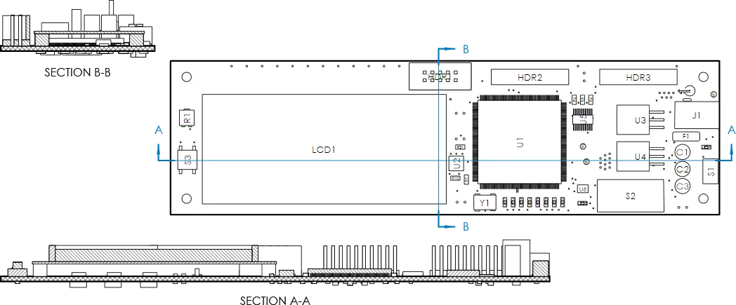
After a Section View has been placed, it can be dragged to a new location, or its associated cut line moved to a different position on the Assembly View. To do the latter, select the Section View and then drag its cut line to a new position on the Assembly View – the Section View graphics will update accordingly. See the Board Section View object page for more information.
Any number of Board Section Views can be created from an Assembly View, and the section properties may be modified after they are placed. Select a Section View and use the Properties panel to set the view's visual properties, such as its scale, label, style, and orientation.
► See Board Section View Properties for information on the property settings available for a Section View.
Board Isometric View
A Draftsman Board Isometric View is a standard isometric projection graphic of the currently specified PCB assembly. It can be placed in a document with the Place » Board Isometric View command.

The properties and option settings for a placed Isometric View are available in the Properties panel when a placed Isometric View is selected in the workspace. In the panel's Properties section, use the Face Side drop-down menu to select the projection view perspective, and the Variants menu to specify which project design variation (if available) is shown.
► See Board Isometric View Properties for information on the property settings available for an Isometric View.
Board Realistic View
A Draftsman Board Realistic View provides a high level of purely visual information to Assembly and Fabrication data in a drawing document
Placed as a separate and configurable view object, the Realistic View provides a scalable 3D rendering of the current board design. The 3D view is generated by the software’s 3D rendering engine – as applied in the PCB Editor and for 3D print outputs – and may be set to adopt the PCB Editor’s current view angle and configuration.

The Realistic View is available for placement from the Place » Additional Views » Board Realistic View command on the main menu, or from the additional views drop-down menu on the Active Bar.
Use the Properties panel options (View » Panels » Properties) to set the visual properties of a placed and selected view. The Properties section of the panel includes a Custom view setting that allows the view display properties to be set from the current PCB Editor 3D view.
Use the  button for the view to adopt the PCB Editor’s current 3D view.
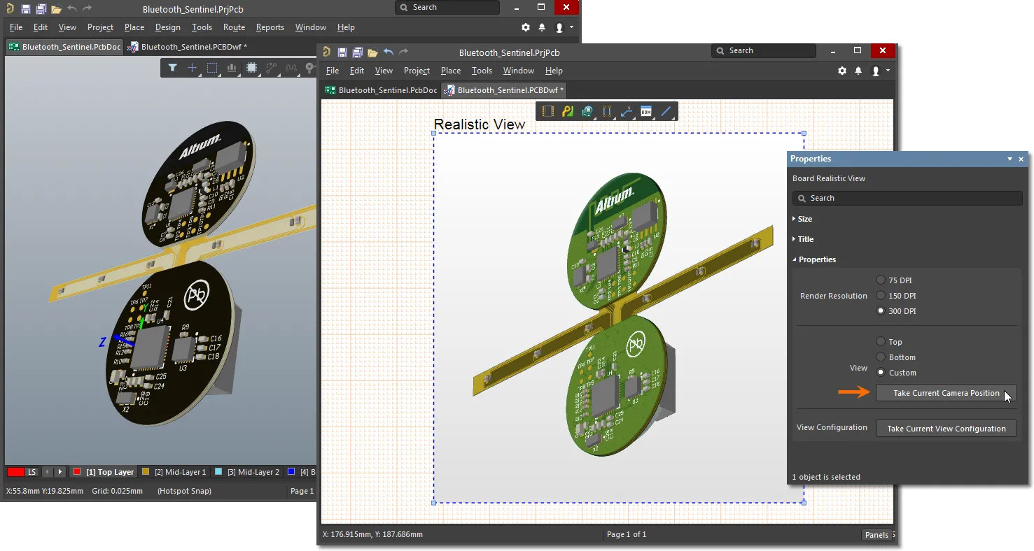
Use the  button to adopt the view settings that are currently applied in the PCB Editor 3D view – as defined in the editor’s View Configuration panel (set to Layer colors in the below example).
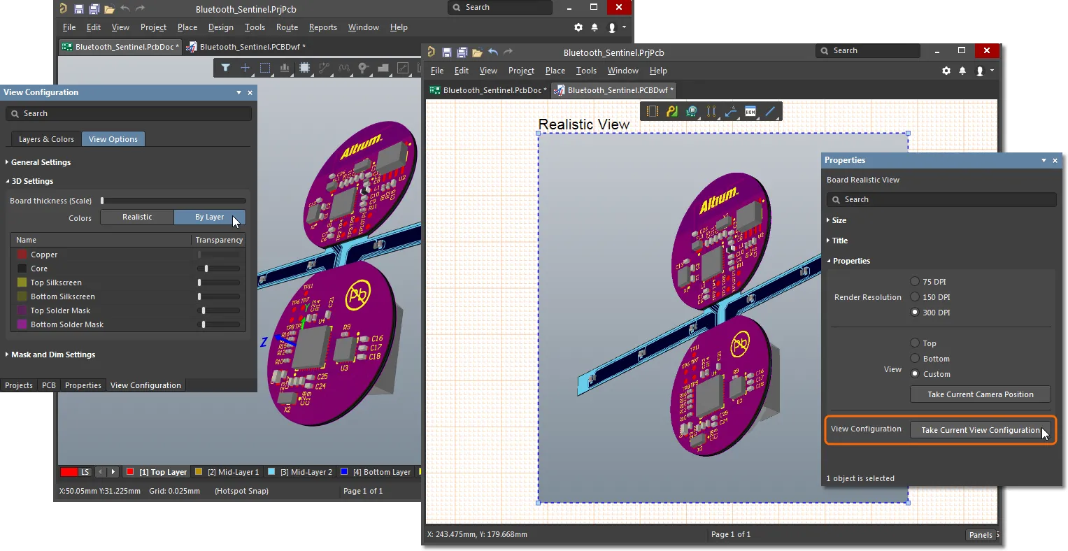
Since a Board Realistic View is able to adopt the current settings of the PCB Editor 3D view, multiple Realistic View objects can be placed in a Draftsman document where each takes a different configuration/view 'snapshot' from the PCB Editor's 3D view.
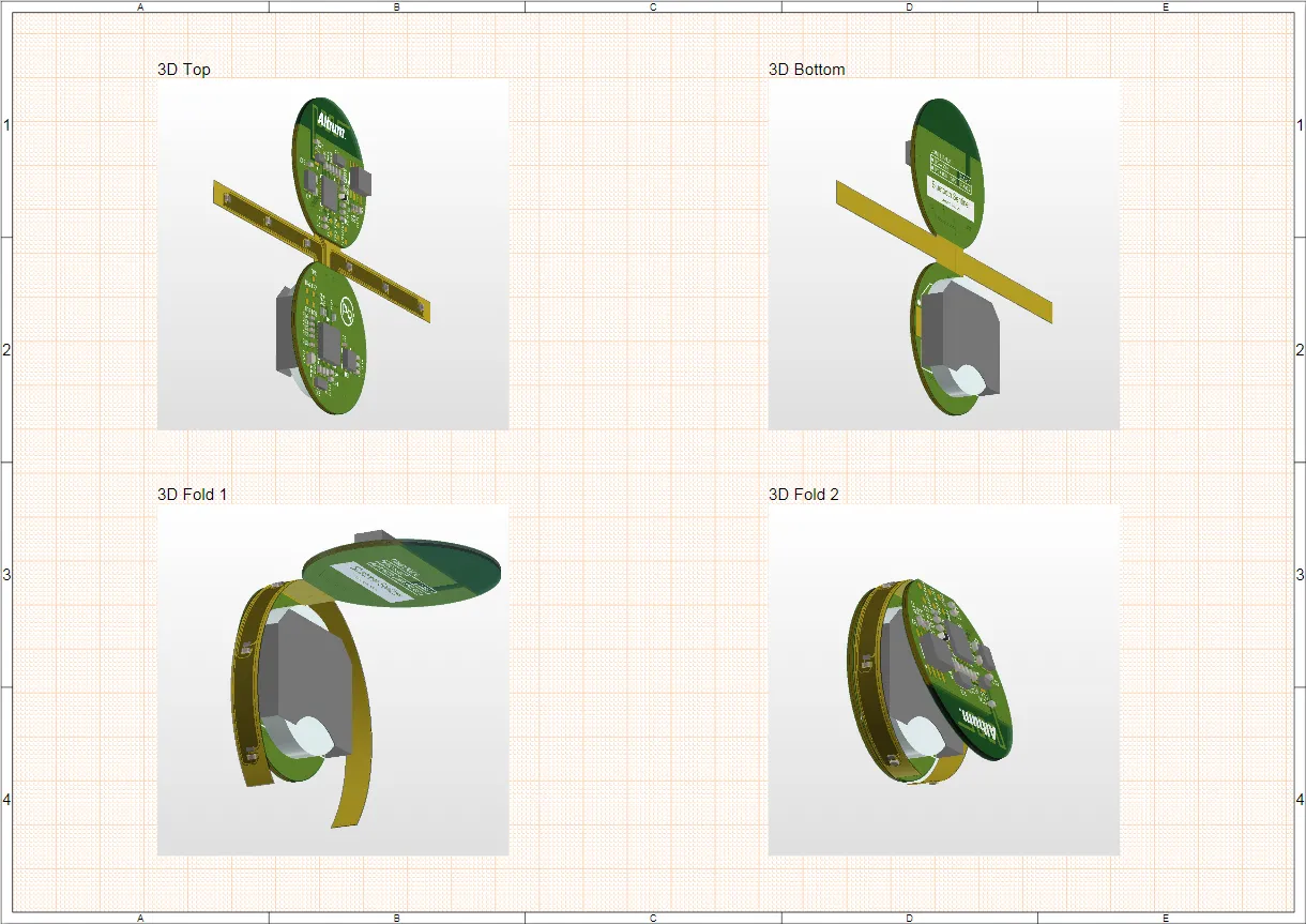
► See Board Realistic View Properties for information on the property settings available for a Realistic View.
Board Region View
The Board Region View allows a Draftsman document to include an accurate representation of multiple Layer Stack regions in a board design, such as those applied in Rigid-Flex PCB designs. The Region View is available for placement from the Place » Additional Views » Board Region View command on the main menu, or from the additional views drop-down menu on the Active Bar.
A Callout placed in the Region View will automatically identify a board Layer Stack region, and dimensions may be added to the view to provide details of the stack region areas and divisions.

Layer Stack naming and data applied in the Region View is drawn from the PCB design, as represented in the PCB editor’s Board Planning Mode view and Layer Stack Manager.
► See Board Region View Properties for information on the property settings available for a Region View.
Component View
A Draftsman Component View is an Assembly View -style drawing object of a single component from the current board design. When set as a profile view, the rendered Component View object includes the related profile section of the supporting PCB.
To place a Component View select Place » Additional Views » Component View, or choose the Component View option  from the Additional Views drop-down on the Active Bar – note that the latter option is enabled when a Board Assembly View has been placed in the document.
 Two placed Component Views, set to the Top and Front View Sides, respectively.
A placed Component View will initially show the first Component registered in the BOM data. This can be changed to the desired component from the Component menu in the Properties section of the Properties panel, which also offers the property settings that define the Component View's graphic style and view angle.
► See Component View Properties for information on the property settings available for a Component View.
Layer Stack Legend
A Draftsman document's Layer Stack Legend view provides a representation of the board's internal structure as an enlarged sectional view. It includes detailed descriptions and information for each layer in the stack, including the Gerber files associated with each layer.
To place a Layer Stack Legend view in a drawing document, use the Place » Layer Stack Legend command or select the  Icon from the Additional Views drop down on the Active Bar.
 A placed Layer Stack Legend derives data from the Layer Stack for the nominated PCB, and can be displayed with relative layer thickness and drill pairs.
By default, the information for each layer is derived from the corresponding attributes in the Board Layer Stack, as defined in the PCB editor's Layer Stack Manager, however, the layer description attributes may be edited and expanded in Draftsman through the Properties panel and the Layer Information dialog.
► See Layer Stack Legend Properties for information on the property settings available for a placed Layer Stack view.
Back Drilling compatibility
Controlled Depth Drilling (Backdrilling) in Altium NEXUS is a methodology for detecting and removing electrically redundant sections of plated through holes.
These are typically found where a standard through-hole Via connects the signal to an inner layer, leaving the remaining portion of the Via barrel as an undesired ‘stub’ – in turn, this stub is likely to compromise the performance of a high speed design. In the backdrilling technique, the stubs are removed by drilling to a precise (Z) depth with a slightly oversized drill.
Altium NEXUS uses a specific Design Rule and assigned Back Drill Pairs to automatically create the correct NC Drill output files. In a Draftsman document this arrangement is represented in the Layer Stack Legend, which includes a graphical representation of all Drill Pairs defined for the board, including any Back Drill Pairs (shown with partially drilled out Via barrels).
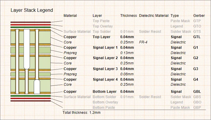
The Layer Stack Legend view showing backdrilling enabled between the Top and Signal 3 layers, and the Signal 4 and Bottom layers.
Note that the Back Drills are defined in the Back Drills tab of the PCB editor's Layer Stack Manager.
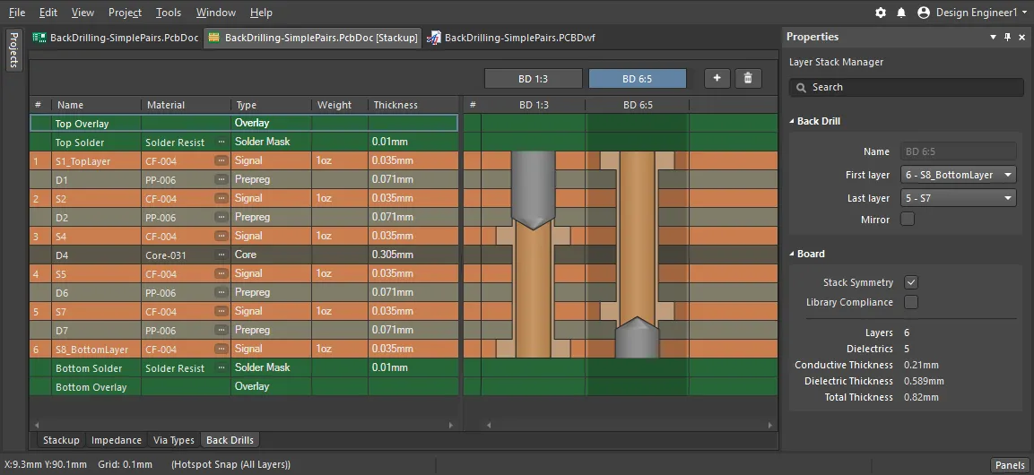
Back Drills are defined in the PCB editor's Layer Stack Manager.
Embedded Board Arrays
The Draftsman editor supports PCB document Embedded Board Arrays, allowing Draftsman documents to provide drawing details of multiple boards placed as a panel array.
When a panelized (embedded array) version of a board design is opened as the file source for a new Draftsman document, the board design data is correctly interpreted by Draftsman as a board array. Choose the project’s board array design as the source from the Document drop-down menu in the New Document dialog (File » New » Draftsman Document), or for an existing Draftsman document, select the board array PCB file from the PCB Document menu in the Source section of the Properties panel when in Document Options mode (no drawing object selected).

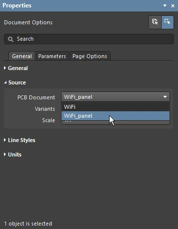
Placed drawing views such as Assembly, Fabrication and Drill Drawing views will extract design data from the source board array PCB file.

Note that when a component is selected in an Assembly view, the Component Display Properties settings in the Properties panel will apply to that component on all board representations within the array.
Geometric Dimensioning and Tolerances
Draftsman includes the capability to place and configure industry standard Geometric Dimensioning and Geometric Tolerances symbolic elements that define the manufacturing properties of objects included in a drawing.
Also used in most advanced MCAD applications, the specialized information provided by the placed geometric symbols stipulates the allowable imperfections in the manufacture of physical objects. The geometric definition elements that can be added to Draftsman documents are derived from standards developed by the American Society of Mechanical Engineers (ASME) – specifically, the ASME Y14.5-2009 Dimension and Tolerancing standard. Many other standards and guidelines exist for geometric engineering definitions, including a large number of conceptually specific documents from the International Organization for Standardization (ISO).
► See Geometric dimensioning and tolerancing for overview information and reference links.
In terms of Draftsman engineering documents, the symbol-based Dimensioning and Tolerancing information is incorporated into a drawing by the placement of two types of objects:
- Datum Feature symbols – Identification objects that can be attached to a line, point or axis of a physical feature in a drawing, such as the edge of the board, component or hole.
- Feature Control Frames – Information objects that can be attached to a drawing feature, which include multiples of symbolic data that specify the mechanical manufacturing constraints for the feature.
Both of the above drawing objects can be positioned freely in the document, or (normally) attached to a feature such as an edge. In the same way in which other Drawing Annotations are placed in Draftsman, such as Surface Finish symbols, the geometric definition symbols are attached by clicking on a highlighted line in the drawing and then clicking again to place the symbol.
Datum Feature
Place a Datum Feature on a drawing using the Place » Datum Feature menu command or by selecting the  icon from the Annotations drop down on the Active Bar. The attached Datum element simply identifies that feature, such as an edge, as a reference on that drawing object.
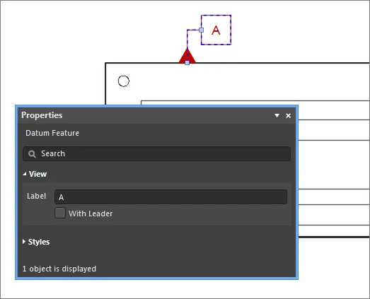
The Datum Feature is identified by its Label entry in the Properties panel, so that relative dimension tolerances included in Feature Control Frames (see below) can refer to this and other placed datum.
► See Datum Feature Properties for information on the settings available for a placed Datum object.
Feature Control Frame
Place a Feature Control Frame on a drawing using the Place » Feature Control Frame menu command or by selecting the  icon from the Annotations drop down on the Active Bar, and attach it to a drawing feature as outlined above, or place it free space.
The information it conveys, presented in symbols, modifiers and numeric values, is entered in the Properties panel.

A Feature Control Frame offers symbol options and a large number of elements that can be attached to specify manufacturing tolerances and constraints. Attached machining tolerances, such as the 'straightness' of a feature, for example, apply to the specified drawing object face. Attached Dimension tolerances by comparison (such as 'position') are generally specified as relative to one or more placed Datum.
► See Feature Control Frame Properties for information on the property settings available for a placed Feature Control Frame.
Applied Geometric Tolerances
When added to the mechanical elements in a Draftsman drawing view, the combined information represented by Feature Control Frames and their related Datum references can fully describe the acceptable manufacturing constraints for that physical element.
In the example drawing view shown below, dimensions have been added, Datum Feature references attached to the three visible board edges, and Feature Control Frames applied to the top edge and two mounting holes. The Feature Control Frames have multiple elements added, which appear as a sequence of (selectable) rows – note the Add, Delete, etc., buttons in the Selected Element area of the Properties panel.
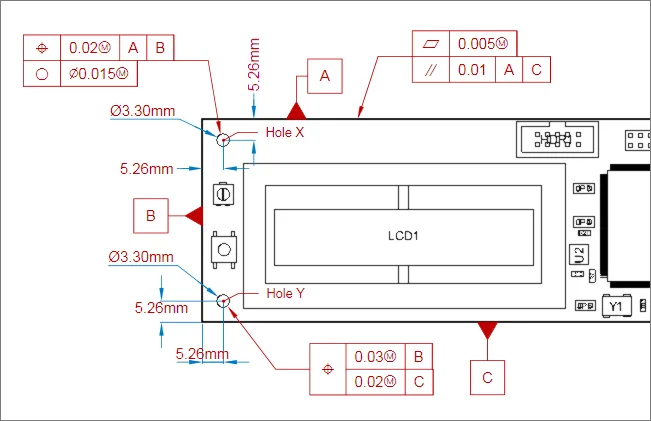
The symbols and formatting used in the various Feature Control Frames is fully described in the ASME standard, however an overview of the examples shown above is as follows:
- Frame attached to edge A
- First element (top row) – stipulates the flatness tolerance (acceptable deviation in the surface) for the board edge.
- Second element – stipulates parallel tolerance (acceptable distance, and therefore angle deviance) between sides A and C.
- Frame attached to Hole X
- First element (top row) – stipulates the hole position tolerance (acceptable positional error) relative to both Datum A and Datum B.
- Second element – stipulates the roundness tolerance (acceptable diameter variance) for the hole.
- Frame attached to Hole Y: A Composite Feature Control Frame (as selected by the related checkbox in the Properties panel)
- Symbol for this frame (first column) – defines this Frame as positional information, for all elements (rows).
- First sub element – stipulates the tolerance (acceptable error) for Hole Y relative to Datum B.
- Second sub element – stipulates the tolerance (acceptable error) for Hole Y relative to Datum C.
The default settings for the Draftsman Geometric Tolerancing symbols (Datum Feature and Feature Control Frame) are available in the Draftsman
Preferences dialog – see the related sections under
Defaults.
Annotation and Drawing Tools
Altium Draftsman provides a range of additional drawing and annotation tools designed to add important information to a Draftsman drawing document. These include both automated note and highlighting systems plus free-form drawing capabilities.
The Active Bar (positioned at the top of the workspace) offers a range of drop-down menus that include placement commands for all Annotation, Table and Drawing objects. The Draftsman dimensioning tools apply to a placed Board Drawing views and are available from their respective icons on the Active Bar Dimensions drop-down.
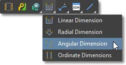
Annotation placement commands are also available from Draftsman's main Place menu, or from the Drawing Annotations toolbar – View » Toolbars » Drawing Annotations.

Format Painter
The Format Painter feature offers a simple and fast way to transfer an existing text style to other Draftsman text elements.
As demonstrated in the below animation, select an existing text element that has the style properties (as defined in the Properties panel) that you would like to propagate, and then choose the Format Painter tool from the Drawing Document Standard toolbar – or Edit » Format Painter from the main menu. This action effectively captures the style properties of the currently selected text.
Use the cursor, which changes to the Format Painter tool icon ( ), to locate and select other text elements that will adopt the style properties. Compatible text objects include editable text elements such as object Titles, Text items and Note items.
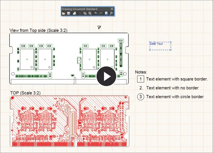
Dimensions
Object dimension graphics may be placed on Board Views (Assembly, Fabrication, Section, Details, etc) to indicate the lengths, sizes, and angles of the object outlines, or the distance between nominated objects. To place a dimension graphic, select the desired type from the Place menu or from the Dimension drop-down on the Active Bar.
Measurement units:
Note that the units system (Metric or Imperial) that applies to a Draftsman document is defined by the Units settings in the Properties panel when in Document Options mode. However, for individual objects such as Linear/Radial Dimensions, Drill/BOM Tables and the Layer Stack Legend, their default units may be preset to Imperial or Metric in the Draftsman – Defaults page of the Preferences dialog. These settings will override the document's base Units setting when a new object of that type is placed.
In turn, the Units used by the placed object can be locally changed through the Units option in the Draftsman Properties panel, when the object is selected.
Linear Dimension
A Draftsman Linear Dimension graphic can be added to an object's outline edge or between two object vertices. This allows a dimension to be placed on the side of an object, between two points on an object, or between nominated sides/vertices of two different objects.
To place a Linear Dimension, select Place » Linear Dimension from the main menu or the  icon from the Active Bar dropdown. A dimension graphic can be moved after it has been placed in an angular plane (horizontal, vertical, diagonal), and the dimension text placed within or outside the Extension lines.
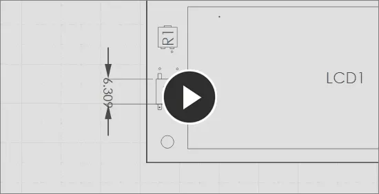
Additionally, the starting/target point for a placed Linear Dimension (or Callout) can be moved to a new location through a drag and drop action. When moved, the starting node binds to the new object and causes the dimensional data to update accordingly, as shown in this ![]() animated demonstration.
animated demonstration.
Most aspects of a placed dimension are available for editing in the Linear Dimension mode of the Properties panel – select a placed dimension to enable its associated panel mode.
► See Linear Dimension Properties for information on the property settings available for a placed Linear Dimension.
Radial Dimension
A Draftsman Radial Dimension can be added to a circular board object (hole) on a Board Assembly View or an associated graphic such as a Board Detail View. The text of the placed Radial Dimension reports the board object diameter.
To place a Radial Dimension, select Place » Radial Dimension from the main menu or the  icon from the Active Bar dropdown.
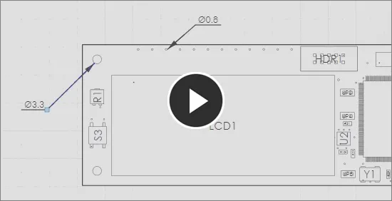
The Radial dimension measurement graphic can be moved (select and drag) or edited in a similar way to the Linear Dimension graphic. Again, most aspects of the placed dimension are available for editing in the Radial Dimension mode of the Properties panel – select a placed radial dimension to enable its associated panel mode.
► See Radial Dimension Properties for information on the property settings available for a placed Radial Dimension.
Note that Draftsman will automatically detect (and convert if necessary) a dimension that has been manually entered in the Properties panel with a specific Units suffix – such as mm or mil. When a dimension is entered without a suitable suffix, the figure is assumed to be in the Units that are configured for the document or object.
Angular Dimension
A Draftsman Angular Dimension can be added between two object edges (or a Center Mark crosshair line) on a Board Assembly View or an associated view such as a Board Detail View. The automated dimensioning graphic reports the relative angle between two object faces, such as the sides/edges of a component or board.
To place an Angular Dimension, select Place » Angular Dimension from the main menu or the  icon from the Active Bar dropdown.

The Angular dimension measurement graphic can be moved (select and drag) or edited in a similar way to the Linear Dimension graphic. Most aspects of the placed dimension are available for editing in the Angular Dimension mode of the Properties panel – select a placed angular dimension to enable its associated panel mode.
► See Angular Dimension Properties for information on the property settings available for a placed Angular Dimension.
Ordinate Dimension
A Draftsman Ordinate Dimension is composed of multiple linear dimension elements that are relative to a single reference point. The indicated dimensions are effectively cumulative as they are placed at increasing distances from the nominated reference point, and can be placed on the outlines edges or vertices of a placed board view or its constituent objects.
To place an Ordinate Dimension set, select Place » Ordinate Dimension from the main menu or the  icon from the Active Bar dropdown. The first location selected is the base coordinate that acts as the reference for the subsequent dimension points.
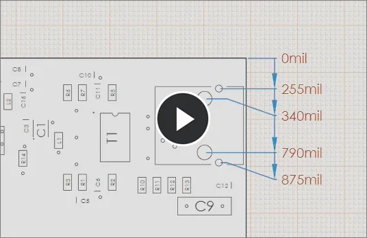
A series of Ordinate Dimensions are treated as one object, but individual entries can be added and removed.
A placed Ordinate Dimension set can be graphically edited by adding dimension points to the ordinate set or removing existing dimensions from the set. The visual style of the dimension lines and text are editable in the Properties panel when a placed Ordinate Dimension is selected.
► See Ordinate Dimension Properties for information on the property settings available for a placed Ordinate Dimension set.
The set of dimensions behave as one object, and can, therefore, be moved as a single entity or edited as an object in the Draftsman
Properties panel. However, note that individual dimensions may be added or removed when the Ordinate Dimension object is selected.
Callout
A Draftsman document Callout is used to provide further information on components and general objects in Board Views. The Callout text information can be synchronized indicators for BOM entries and Note items, a specified Component Parameter or custom text.
To place a Callout, select Place » Annotations » Callout from the main menu or the  icon from the Active Bar dropdown. During placement, the Callout object will change between its 'attached' mode and free mode in response to the underlying object. When hovered over a side or corner of an object, the highlighted dot or line indicates that the Callout will be attached to that object – when not highlighted the placed Callout will refer to a location, rather than an object.
 Smart Callout text can be placed and configured to read the matching BOM entry for a component, refer to an existing Note Item entry, or just display custom text.
The starting/target point for a placed
Callout (or
Linear Dimension) can be moved to a new location through a drag and drop action. When moved, the starting node binds to the new object and causes the Callout data to update accordingly, as shown in this
![]() animated demonstration
animated demonstration.
The Callout Source Text option in the Properties section of the Properties panel will determine the context of the text attached to the Callout (its 'tag'). By default, an attached type Callout will display the BOM entry of the component it is attached to, and a general type Callout will show a custom text string – initially set to '?'.
► See Callout Properties for information on the property settings available for a placed Callout.
Center Mark
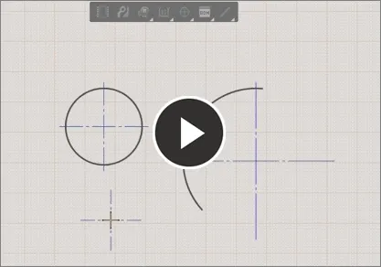
The Draftsman Center Mark object is placed on Circle and Arc objects in a drawing document. When placed, the Center Mark object detects and locks to the center point (radius origin) of the Circle or Arc, and is then available as a reference location for placed dimension objects such as Linear and Ordinate dimensions.
To place a Center Mark, select Place » Annotations » Center Mark from the main menu or the  icon from the Active Bar dropdown. During placement, hover the cursor over a Circle or Arc outline to snap the crosshair to the Circle/Arc center, and then click the highlighted outline to confirm the Center Mark object binding.
Center Marks placed on a drawing document are available for dimension bindings. When placing Linear or Ordinate dimensions, select the highlighted dot at the intersection of the Center Mark cross as a dimension reference node.

The line style and color of a Center Mark’s indicator cross are available as settings in the Properties panel. The panel also includes a marker Rotation property that can be used to document the angular placement of circles/arcs in a drawing. In this case, a placed Angular Dimension uses one line of a Center Mark cross as an angle dimension reference.
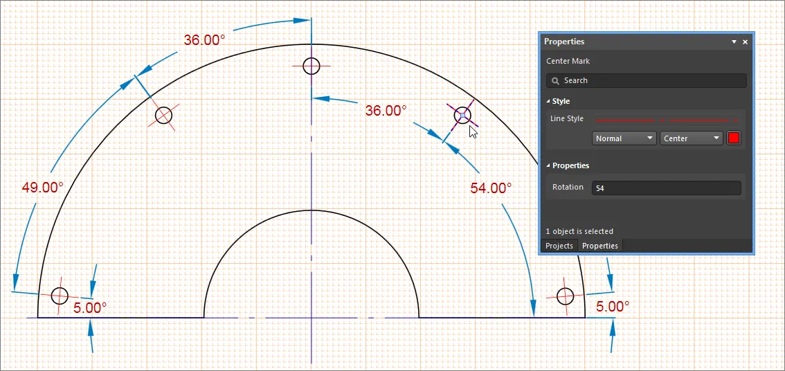
► See Center Mark Properties for information on the property settings available for a placed Center Mark object.
Surface Finish Indicator
Draftsman allows the placement of Surface Finish graphical symbols and their associated parameters that comply with the ISO 1302:2002 International Standard for surface texture in technical product documentation. The standard specifies the rules for the indication of surface texture in drawings, based on special symbols and attributes that describe the permitted surface material for the product – in this case, a printed circuit board.
The addition of Surface Finish indicators in Draftsman avoids the need for a separate Surface Finish tool or application when this standardized information is required for PCB manufacture. The graphical symbols are accompanied by a range of specialized text codes, as defined by the ISO standard, that are added via the Draftsman Properties panel when a placed Surface Material object is selected.
To place a Surface Material symbol in a drawing, select Place » Annotations » Surface Finish from the main menu (or the  icon from the Active Bar), and then locate the symbol where it is associated with the board surface. Attach the symbol to a drawing by clicking on a highlighted line and then clicking again to place the symbol. The attached surface indicator can be dragged along the line, and optionally, away from the drawing via an automatic Extension Line – enabled by the With Leader option in the Properties panel.
A Surface Finish indicator may also be placed in free space, and not attached to (or associated with) a specific drawing view surface – see the symbol styles information below.
► See the Surface Finish object page for more information on placement and editing.
In most cases only one or two surfaces need to be defined, such as the surface of the top and bottom layers, so a minimal number of symbols/attributes are usually required. However, the indicators may be applied to the face of any engineered object, including the surfaces of rendered components.
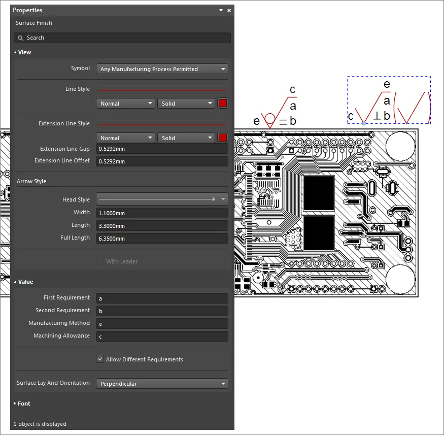
The style of the Surface Finish symbol itself indicates the allowed processing of the surface material, as follows:
-
 Any manufacturing process permitted (default).
-
 Material shall be removed.
-
 Material shall not be removed.
- A symbol enclosed in brackets is appended to the indicator when the panel's Allow Different Requirements option is checked. This style of Surface Finish indicator, which is placed in free space, specifies a default requirement for all surfaces unless otherwise specified (by other surface indicators that are attached to particular object faces/surfaces).
The string-based parameters (attributes) that are associated with the symbol indicate a range of manufacturing options, as defined by the standard:
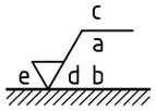
- First requirement (
a)
- Second requirement (
b)
- Manufacturing Method (
c)
- Surface Lay and Orientations (
d)
- Predefined options, with matching symbol graphics, as selected from the drop-down menu in Draftsman's Properties panel (default is
None)
- Machining Allowance (
e)
By default, no parameters are included when a Surface Finish indicator is first placed. The default Surface Finish indicator settings can be edited in the Draftsman
Preferences dialog – see the
Surface Finish Sign section under
Defaults.
► See Surface Finish Properties for information on the property settings available for a placed surface Finish object.
► See the ISO Geometrical Product Specifications page for more information about the ISO 1302:2002 standard.
Solder and Glue joint Symbols
The GOST defined symbols for Soldered and Glued joints provide further mechanical information that can be included in Draftsman design production documents.
The symbols for indicating glued and soldered mechanical joints are governed by the GOST 2.313-82 drawing standard for mechanical connections, and are available as special options in Draftsman’s Callout object.

When a Callout has been placed to indicate a glued or soldered mechanical connection, the special symbols can be selected from the Symbol drop-down menu in the Properties panel.
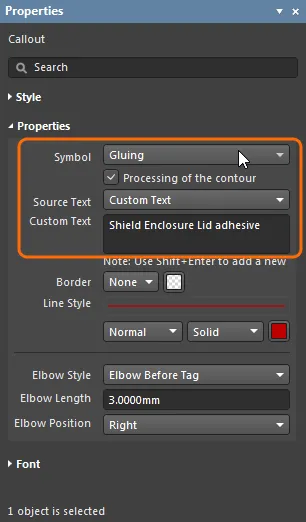
The Symbols and options are defined as follows:
-
 Gluing – indicates mechanical joint areas for gluing.
-
 Soldering – indicates mechanical joint areas for soldering.
-
 Processing of the contour option – check when a glue or solder joint seam is to be made in a closed area. Places a circle symbol at the end or elbow of the Callout line.
► See Callout Properties for information on the property settings for Solder and Glue symbols.
Note
Draftsman document Note Item lists can be placed as free text entries in any location and used to provide additional information about the current Draftsman drawing. The Note entries may be referenced by Callouts, and include smart strings that interpret any available Parameters (see below).
To place a Note Item, select Place » Annotations » Note from the main menu or the  icon from the Active Bar, and then click to place the default Note entries in the drawing space. Select an entry in the list to edit its text content and number icon style in the Properties panel. Use the Add/Delete buttons to include and remove list entries, and configure the order of the text entries using the Up/Down buttons.

Select a single entry in a Note Item list to edit its content in the Properties dialog.
► See Note Properties for information on the property settings available for a placed Note list object.
To use a Parameter in a Note entry, along with its related text, first select the relevant note entry and then the  icon in the Properties panel to open the Document Parameters dialog. Choose from the listed Parameters in the dialog and select OK to confirm the selection – the Parameter string will be inserted at the current cursor position within the Note Description text box.

Tables
A Draftsman document allows Bill Of Materials (BOM), Drill and range other data tables to be placed on the drawing and subsequently configured in the Properties panel. The tabular data is directly derived from the project PCB files and provides a simple, visual way to convey crucial information for the PCB fabrication and assembly processes.
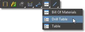
The BOM/Drill/Table placement options are available from the main Place menu or from their respective icons in the Table drop-down on the Active Bar.
BOM Table
A Draftsman Bill Of Materials (BOM) is an automatically generated table object that lists the physical assembly items in a PCB design. The BOM table data is derived directly from the project PCB file, or if one is present in the current project, an Active BOM document.
To place a BOM table, select the BOM table placement tool  and click to position the table on the drawing document. Select the placed table to access its property settings in the Properties dialog, which provides configuration options for most aspects of the BOM table, including its visual attributes and data content source.
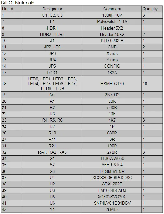
The data included in a Draftsman BOM table is determined by settings in the Properties panel and the potential presence of an Active BOM document in the project:
- When an ActiveBOM document is available in the current project, its configuration and content become the data source for a Draftsman BOM Table. Note that this applies when the Data Source entry in the Properties panel is set to Project – an available ActiveBOM document is not used as a source when the Data Source property is set to Board.
- When an ActiveBOM document is not included in the project (or the Data Source option is set to Board), the data in a Draftsman BOM Table is drawn directly from the source project files. An Alias entry for a table column entry Name (available in under the Properties panel’s Columns tab) is then editable since it is not determined by an Alias property entry in an ActiveBOM document.
In general, the Properties panel options can restrict BOM entries to those included in the Board layout (as opposed to the entire PCB project, including any custom component Parameters) or to a specific Variation of the design. Further tailoring of the included entries is available through specifying the top or bottom view of a placed Board Assembly View.
► See Bill of Materials Properties for information on the property settings available for a placed BOM table.
Note that the properties of a newly placed BOM table are defined by Draftsman's Default Preferences.
Use the Properties panel's Columns tab to manage the BOM table's data columns. This allows control of the BOM table column visibility, text alignment, width and data sort order. BOM Table headings may be changed by entering an Alias for a table column parameter name – applies if an ActiveBOM document is not determining the table content (see above).
 Manipulate the columns of a placed BOM Table in the Columns tab of the Properties panel.
► See Bill of Materials Properties and BOM Management with ActiveBOM for more information on configuring BOM Table columns.
Split BOM tables
The Bill of Materials (BOM) document for most advanced PCB projects tends to have a large number of entries, which can be difficult to recreate as a table that will fit into a drawing document. Rather than resorting to font and table scaling, multiple custom table entries or an external document, the Split BOM capability in the Properties panel allows a BOM Table to be presented over a number of 'pages'.
To create the multiple BOM Pages, select a placed BOM (which is likely to exceed the document Sheet height) and check the Limit Page Height box in the Properties panel’s Pages section. This will restrict the height of the BOM table to the nominated height entry (Max Page Height, mm), and therefore the number of lines shown in the BOM table.
 Hover mouse cursor over image to see the Limit Page Height result.
Draftsman detects that the entire BOM is not shown, as indicated by the panel's Page entry (for example, 1 from 2), and the associated drop-down menu allows you to nominate which Page is shown. To add further Pages of the BOM (here, BOM Table ID: 0), place another BOM (Place » Bill of Materials) and specify the next page under Page in the Pages section of the Properties panel.

Since each Page of the BOM is placed by adding another BOM table then configuring it accordingly, the individual BOM Pages (sections) can be placed on any Sheet in a Draftsman document. To place another, different set of split BOM Pages, specify an alternative BOM Table ID on a placed BOM – say, 1 rather than 0.
Note that the Max Page Height property specifies the height of the first page in the BOM Table. When the second page is selected (Page 2), the Max Page Height property is defining the height of the first excluded page (Page 1). Page 2 therefore shows the remaining BOM entries. Start by making the Max Page Height property identical for each page.
Table
A Draftsman document allows a generic Table to be placed on the drawing and subsequently configured in the Properties panel, and in the table cells themselves. The layout and content of the custom Table is free to be defined as required by its intended purpose, and offers a flexible way to include additional information in any Draftsman document.
A Table is placed from the main menu (Place » Table), or from the Table icon ( ) on the table drop-down of the Active Bar. Use the following Insert Table dialog to nominate the initial number of rows and columns in the new Table, and therefore its number of cells.

Nominate the number of cells in the Table's rows and columns – these can be modified later via a cell's right-click Table commands.
Data is entered by typing (or pasting) directly into the cells, while the Table's graphics and text attributes are defined in the Properties panel. The Table object offers a wide range of text and structure editing features, which can be implemented on a cell row or column basis using standard Shift/Ctrl or drag selection techniques.
► See Table Properties for information on the property settings available for a placed Table object.
To move a Table, click in a cell and then drag by its handle icon (

). To delete a Table, select its Title and then press the
Delete key or select
Edit » Delete from the main menu.
Special strings in Table cells
A Table supports the inclusion of document Parameters as Special Strings. Project, System, PCB, and User Parameters will be converted to their Values when entered as a Special String in the Table cells. Draftsman document Parameters are accessible under the Parameters tab in the Properties panel, when in Document Options mode.

The table's handling of Parameter strings also includes the ability correctly transfer Special String data to and from a spreadsheet, by using standard copy/paste techniques.
- When pasting Special Strings into a spreadsheet from Draftsman, the target spreadsheet cells will be populated with the string’s interpreted Value.
![]() ► Demonstration video.
► Demonstration video.
- When pasting Special String data from a spreadsheet into Draftsman, the pasted text will be interpreted as a Special String Value – providing the Special String is matched to an available System, Project or User parameter.
![]() ► Demonstration video.
► Demonstration video.
When preparing Special String entries in a spreadsheet you will need to prefix each Value entry with an apostrophe, so the cell content will be treated as text data. For example the special string for the Units parameter would be entered as: ‘=DocumentUnits
Alternatively, all spreadsheet cells could be set to Text format.
Table structure
Right-click in a cell and select the Table menu from the context menu to access the cell configuration commands. These provide a full set of Table manipulation functions for adding and removing Columns/Rows and Merging Cells.

The right-click Table commands offer a range of standard table manipulation functions.
By using both the Table commands and the options available in the Table's Properties, a custom Table can be created to suit a wide range of information needs in a Draftsman document. The table shown below, for example, has been constructed to show the information taken from a board Stack Report.
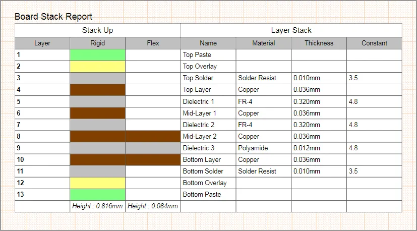
A Custom Table can be constructed to host a wide range of different PCB assembly and fabrication information.
Drill Table
A Draftsman Drill Table presents a tabular view of board drill symbols and associated data, where a Symbol row, representing a specified type of drill hole, can include a range of hole information such as its size, plated construction and population count. Holes types are grouped under symbols as specified in the Drill Symbol Configurations dialog.
To place a Drill Table for the current PCB, select Place » Drill Table or use the Drill Table icon ( ) on the table drop-down of the Active Bar.
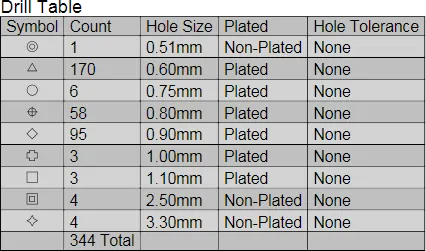
Set the visibility, order and sorting for Drill Table column data in the Properties panel.
Select the placed Drill Table to access its property settings in the Properties panel. This provides configuration options for most aspects of the Drill Table, including its visual attributes and data content (through options in the Properties and Column sections).
► See Drill Table Properties for information on the property settings available for a placed Drill Table.
The Drill Table's Symbol styles, and the grouping of drill hole types under those symbols, is determined by the settings in the Drill Symbol Configurations dialog opened from the Properties panel's  button (in the Properties section). This is the same dialog that is activated from the Properties panel when in Drill Drawing View mode, but in this case, only those columns activated (made visible) for the Drill Table will be shown. Note that the two Drill Symbol Configuration dialogs versions are from the same source and therefore interact.
Transmission Line Structure Table
The calculations applied in controlled impedance routing result in trace structures that aim to satisfy a target transmission line impedance, and therefore the board design’s high-speed and/or EMF requirements.
Board layers and their specified or calculated properties are accessed through the Layer Stack Manager, where impedance controlled routing layers are associated with definable Impedance Profiles. The board materials and dimensions in each profile are applied to its Transmission Line impedance calculations, which results in a given trace structure. The structure accommodates both single traces and differential pairs, and Stripline (internal) or Microstrip (surface) board layer formats.
► See the Defining the Layer Stack for more information.
Since the structure and associated data for each Transmission Line definition in the board Layer Stack is important information for the PCB manufacturing process, Draftsman includes a dedicated Transmission Line Table object to document this information.
The table is populated by data drawn from the Layer Stack Manager and its Transmission Line impedance calculations.
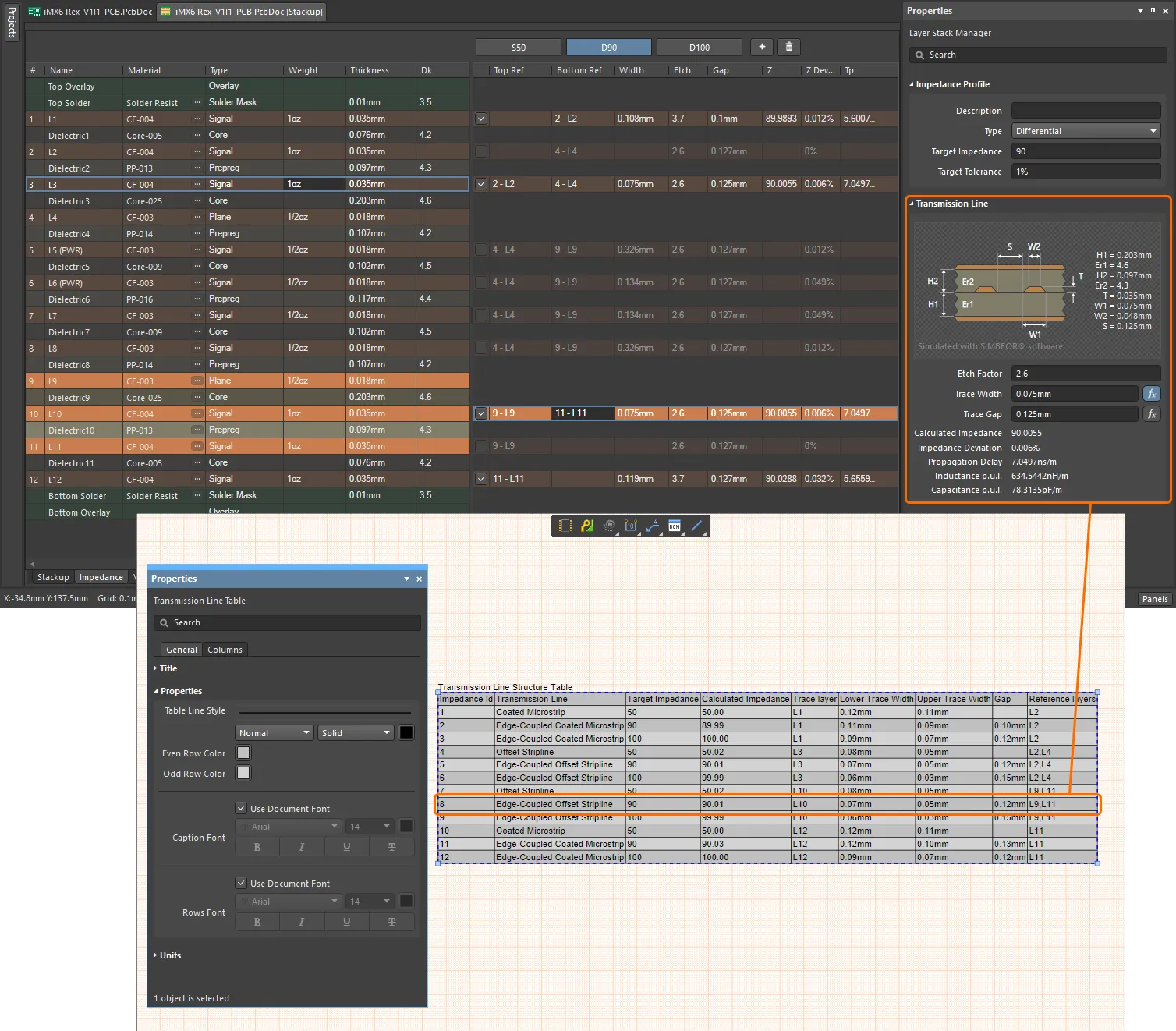
The Transmission Line Table object is available for placement from the Place » Transmission Line Table command on the main menu, or from the Table objects drop-down menu on the Active Bar. Use the Properties panel to set the table style (colors, lines, font, etc.,), and under its Columns tab, which data columns are displayed.
► See Transmission Line Table Properties for information on the property settings available for a placed table.
Graphical Tools
Draftsman provides a range of graphical element tools that can be used to place basic, free-form drawing elements in a document. The tools are accessed from the main Place menu, from the Graphical Tools drop-down menu ( ) on the Drawing Annotations toolbar or the graphic tools drop down on the Active Bar.
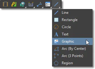
Place a graphic element by clicking to position its first node/point and then again to place following nodes, therefore determining its size – such as the length for a line, the radius for a circle, the distance between opposite vertices for a rectangle or text box, or the dimensions of a placed image graphic. The nodes will snap to the nodes or guidelines of other objects, and optionally, the document snap grid if enabled.
► See the snapping options in the General section of the Document Options for graphical primitives snap settings.
Placed graphical elements can be moved by selecting and dragging, or when multiple elements are selected (Ctrl-shift + click, or by lassoing). Individual nodes can also be selected and moved. For more options, select a placed graphical element to enable its associated mode in the Draftsman Properties panel.
► For more information on Draftsman graphical objects, and their associated settings in the Properties panel, see:
DXF Import
Draftsman provides further graphical options through the import of standard DXF files, which are loaded into the drawing space from the File » Import from DXF menu command. Use the Windows file browser to select a *.DXF or *.DWG file then configure the import options from the DXF Import Settings dialog that opens.
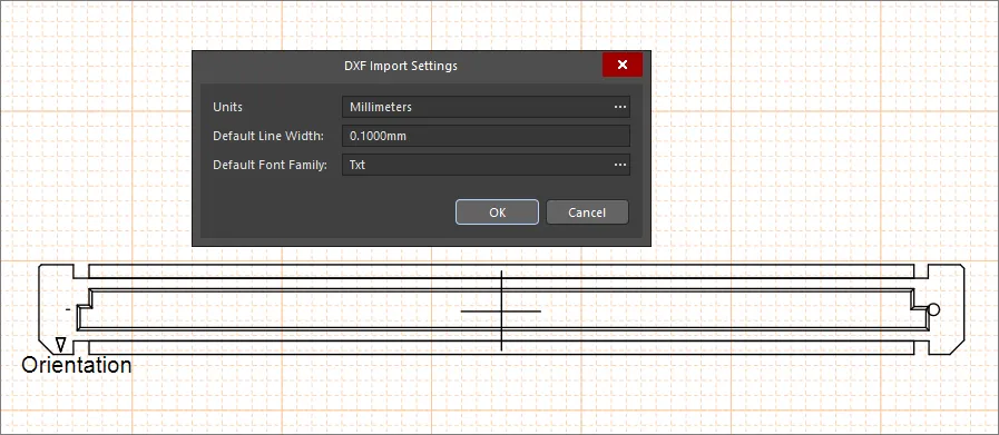
Note that the DXF source graphic is interpreted using Draftsman’s standard graphical shape objects – lines, circles, rectangles, text – and each primitive object is therefore editable.
Documentation Outputs
Draftsman documents may be printed or generated as output files in the same manner as other graphics-based documents in Altium NEXUS (Schematic, PCB, etc.). New Draftsman documents (once saved) are automatically added to the associated PCB project and are, therefore, available to all normal document generation and printing processes.
Print or Export to PDF
To print the currently active drawing document, select File » Print from the main menu (or Ctrl+P) and select the print options in the normal way. For Draftsman documents, the print dialog includes a scalable print preview with page navigation selectors.
To export a drawing document to a single or multi-page PDF file (as determined by the document structure), select File » Export to PDF from the main menu.
Add to OutJob
A Draftsman drawing document is added to an OutJob by first opening an existing Output Job file or creating a new Output document (File » New » Output Job File).
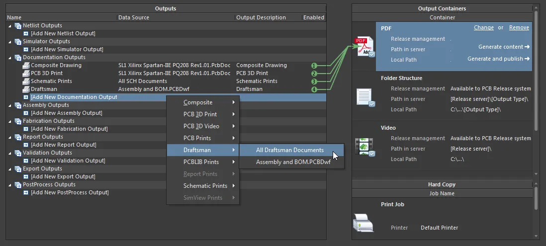
To add a Draftsman document to the output job, select the Add New Documentation option under the Documentation Outputs section, and then select Draftsman and a PCBDwF file (or all available documents). Assign the newly added Output file (*.PCBDwF) to a PDF output by selecting that container option and then checking the enable option associated with the Draftsman entry.
Variant Parameters and OutJobs
Altium NEXUS has the ability to create variations of a board design (Variants) and pass this variant information on to Draftsman, which in turn allows a design variation to be applied to a placed drawing View.
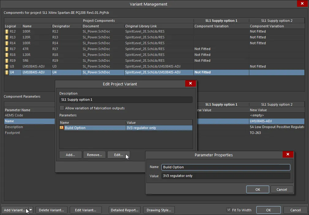
Project Variants are added in the project's Variant Management dialog, which also allows Parameters to be added to each variant. These parameters are typically applied as special (interpreted) strings in Altium NEXUS documents to indicate which Variant is currently enabled.
In Draftsman, a project’s current variant selection is made from the Variation menu in the in the Properties region of the Properties panel, which causes a placed Board Assembly View to change to reflect the variation, and apply mesh rendering where required – see the General section in the Properties panel Document Options for Variant display settings.
Special strings, such as the VariantName and Variant Parameters can be placed in the drawing as free strings, or for a more universal solution, included in the title block of Draftsman sheet templates – see the Document Parameters dialog for a list of the available parameter strings.
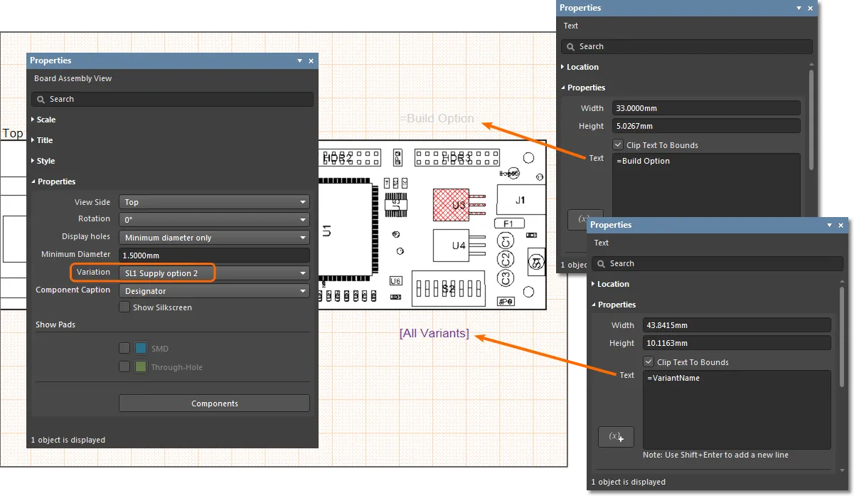
Note that a Draftsman document can have several placed Views, with each potentially set to a different Variant. Since the Variant selection is on an individual View basis, rather than at a document level, any special variant strings placed in the document are not interpreted. When the Draftsman document is printed through an Output Job, the OutJob's current Variant selection (which is at a document level) is resolved by the special strings.
When a saved Draftsman document is subsequently generated from an Altium NEXUS Output Job, the parameter special strings are interpreted in line with the Variant selected in the OutJob. Note that a Variant may be applied to all outputs or specific outputs.

