Database component libraries, which derive their component parameters from a master database, can now be synchronized with that database when the library has been migrated to an Altium 365 Workspace.
With the newly introduced Components Synchronization feature, the data from a selected table within the master database is used to create a fully configured and mapped synchronization profile that may be run on demand or as a timed process. The result is that data updates in the master database will propagate to the matching component parameters in the Altium 365 Workspace.
The feature allows companies that centrally manage component data in an enterprise system database to harness the benefits of an Altium 365 Workspace while maintaining synchronization with their enterprise system (PLM, PDM, ERP, etc) – or simply a shared database or CSV file. In auto synchronization mode, a Windows Task schedule will perform the database to Workspace data update independently of the Altium NEXUS design client.
► See Streamlined Migration of Existing Libraries to Your Managed Content Server for information on migrating database libraries to your Altium 365 Workspace.
- Components Synchronization is provided as an optional platform extension that is enabled in the Configure Platform page (under Importers\Exporters), accessed from the
 button in the Extensions & Updates view.
- The Components Synchronization feature is available to those with a suitable level of Altium Subscription.
Creating a Component Synchronization Configuration
Database to Workspace synchronization is established through the creation and setup of a Components Synchronization Configuration document (*.CmpSync) in Altium NEXUS. When connected to your Altium 365 Workspace, create the new document from the File » New » Components Synchronization Configuration menu command.
Add the desired master data source to the synchronization configuration from the  button, or by dragging and dropping suitable files onto the Data Sources area of the interface. The configuration accommodates the following component parameter data sources:
For database connectivity, the Component Synchronizer requires access to the 64-bit version of the Microsoft OLE DB Provider.
Database connectivity and problem solving
The required 64-bit version of the Microsoft OLE DB Provider is available on the host PC if:
In situations where a 32-bit version of Microsoft Access is installed however, the operating system will not accept the 64-bit Access Database Engine installation. This can be resolved using a specific installation procedure (a 'passive' install), or depending on the PC's software configuration, through other solutions.
► See Using Database Libraries with 32-bit and 64-bit Altium Design Software on the same Computer for full information on the options available.
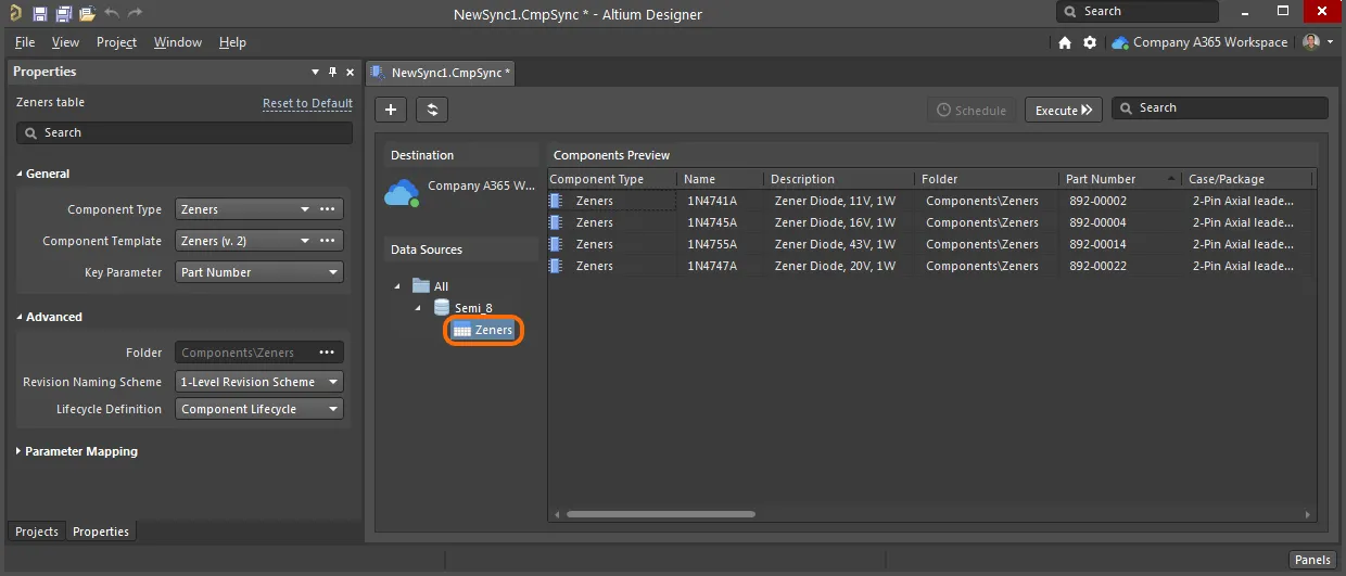
In the below example, a database library for Zener diode components has been added to the configuration – note that this dBLib has previously been migrated to the Workspace. The library's source database (Semi_8.mdb) contains DiodeGP and Zeners tables, where the latter table is enabled for synchronization.

Select the data table (or tables) to be synchronized in the Properties panel, which is then accessed as a parametric data source that populates the Components Preview listing. The system will attempt to establish the type of component (resistor, capacitor, etc) from the parameter data, and then apply that Component Type and its matching Component Template to the configuration – if required, these settings can be manually selected. Select a table entry under Data Sources to see the current configuration in the Properties panel.

In this example the component type (Zeners) has been identified and its managed Component Template applied. The template then determines the target server folder, component Naming Scheme and applied Lifecycle definition. Component entries are matched to source Database entries using a unique identifier, as specified by the Key Parameter entry in the Properties panel – in this case Part Number is used, although Name or even Description would be equally effective.
When a Database Library (*.dBLib) is used as a data source rather than a direct database type source (*.mdb, *.xlsx, etc), the following information is extracted from the dBLib file and applied to the configuration:
- The source database connection and path.
- The database Table selection.
- The Key lookup field (parameter).
These configuration settings will therefore match those used when the dBLib was generated, ensuring correct synchronization between migrated dBLib components and the source database.
Synchronization
Once satisfied with the synchronization setup, save the configuration document and perform the database to server components synchronization from the  button, or setup a scheduled synchronization (
 ).
).
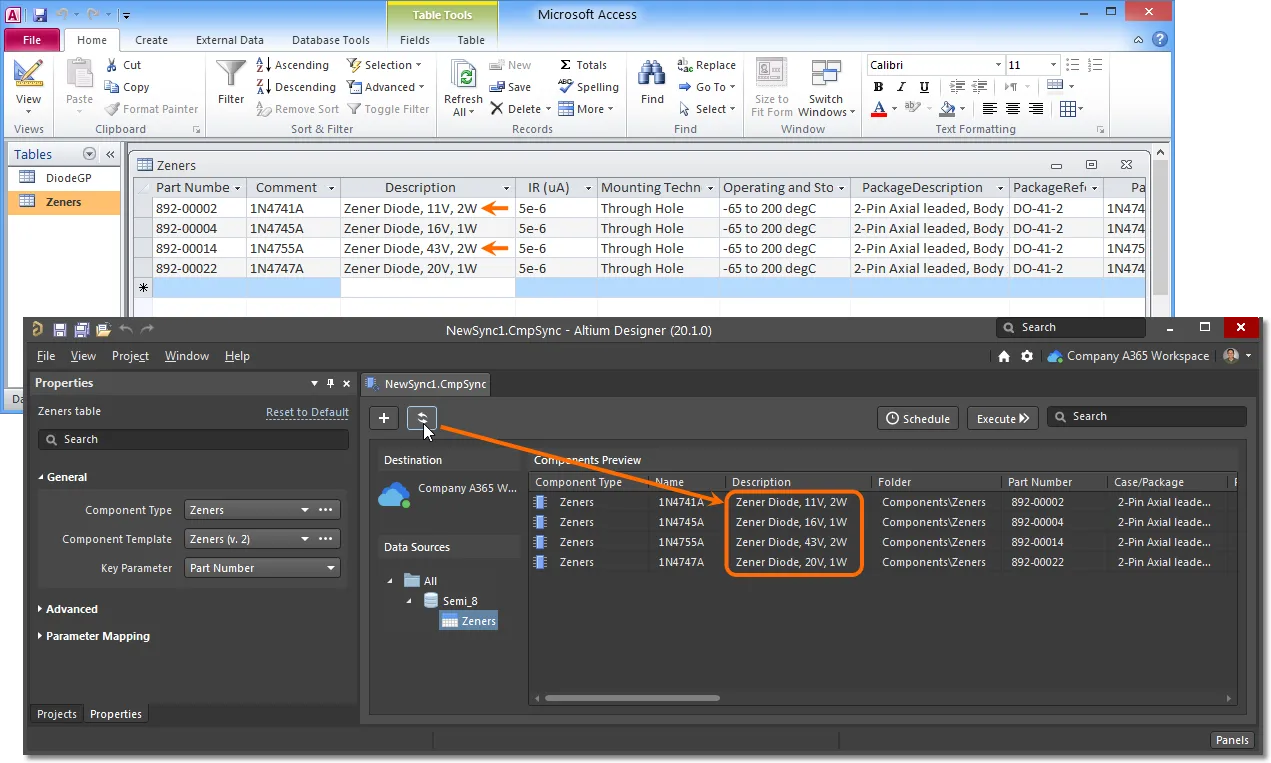
In the example case shown below, the description parameter for two component entries has been updated in the source/master database. These changes can be observed by clicking the refresh button ( ) in the configuration interface – this is optional, and does not affect the synchronization of updated data.

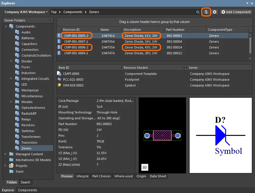
A subsequent synchronization will update the Workspace component parameters from the current database field data. This change can be observed in the Components and Explorer panels. Refresh their views using the F5 key or  button, respectively.
Detailed synchronization log files are available in the system's C:\Users\Public\Documents\Altium\Logs\ComponentSync folder.
As can be seen in the Explorer panel, new revisions have been created for the two updated components. Which parameters will create new component revisions when updated from the master database is determined by the Parameter Mapping settings in the synchronization configuration.

Parameter Mapping
Control of the synchronized parameters is available in the Parameter Mapping section of the Properties panel, which offers a grid listing of the relationship between target server parameters and source database parameters (fields). Also available are settings for the transferred parameter Type (text or unit-aware) and control of new Revision creation for updated parameters.
In terms of parameter mapping, the table columns represent the workspace target (Parameter) and the source/master database fields (Column) – as in the column data shown in the Components Review grid of the main configuration interface. Parameters can be removed from the synchronization (skipped) or remapped to another available parameter. Parameter names can be edited, and parameter sets can be added, edited and removed. The base component parameters (Name, Description) may be remapped, but are otherwise read-only.

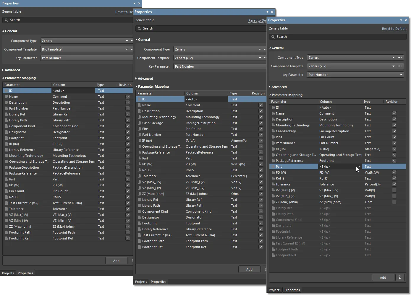
The image above shows three states of parameter mapping in the Properties panel. On the left is when no Component Template is applied, the center image is the result when a template has been specified, and the image on the right demonstrates modified parameter mapping and Revision control.
- Left image: By default, with no template applied, parameters are essentially mapped on a one-to-one basis between the master database and Workspace components. The
ID parameter represents the automatic creation (if required) of the Workspace Revision ID parameter, which relates to the current Item Revision Naming Scheme setting – under Advanced in the panel. Also note that the database Comment field is automatically mapped to the Workspace Name parameter.
- Center image: When a Component Template is applied (
Zeners here), database parameter fields are mapped to their equivalent template parameters. The system will automatically interpret common parameter mappings, such as Pin Count to Pins (a template parameter) in this case. Parameters that are not defined in the template are mapped on a one-to-one basis – the nine parameters at the bottom of the list in this example.
- Right image: A range of database parameters have been removed from the synchronization configuration by setting their column modes to
<skip>. The PackageReference parameter has been mapped to the master database Footprint field. The Revision option has been unchecked for parameters VZ(Max), VZ(Min) and ZZ(Max), which means that a change in their value in the master database will not cause a new Workspace revision to be created when synchronization occurs – the changed value, however, is propagated to the Workspace component as normal.
Scheduled Synchronization
Saved Synchronization Configurations are setup for automated database to Workspace component processing through the Auto Synchronization Schedule dialog, opened from the  button in the main interface.
Scheduled synchronization, in compliance with the current configuration profile, can be set to a specific time of each day, at a particular time on various days of the week, or when you log on to Windows. You can also disable synchronization for when you are not logged on. When your settings are confirmed with the  button, the configuration will be added as a repeating task in the Windows Task Scheduler. Set to No automatic synchronization to remove an existing sync schedule.

Database to components synchronization also can be run from the command line using the ComponentSync.Executor.exe application, found in the software installation's \System folder. The command syntax is ComponentSync.Executor.exe [configuration file name]. A typical example might be:
C:\Program Files\Altium\AD20\System\ComponentSync.Executor.exe C:\Users\Public\Documents\Altium\ MySyncConfig.CmpSync

Depending on the operating system, surrounding quote characters may be required for paths that include spaces.
