Applied Parameters: None
Summary
This command is used to interactively draw a new shape for the current board. The board shape, also referred to as the board outline, is a closed polygon that defines the boundary, or extents, of the board. As well as providing a visual guideline of the extents of the space available for the placement and routing of the design, the board shape is also used by the internal power planes as the reference for the power plane edge pullback and the edge for splitting power planes.
For detailed information about this object type, see
Board Shape.
Access
This command is accessed from the PCB Editor when configured in Board Planning Mode by choosing the Design » Redefine Board Shape command from the main menus.
Access this command quickly by using the D, R keyboard sequence.
The current viewing mode for the PCB document can be changed using the corresponding commands from the main View menu. To switch to Board Planning Mode, use the command of the same name, or use the 1 keyboard shortcut.
Use
After launching the command, the cursor will change to a cross-hair and you will enter the standard polygonal object placement mode. Board shape definition is made by performing the following sequence of actions:
- Position the cursor and click to anchor the starting vertex for the board shape.
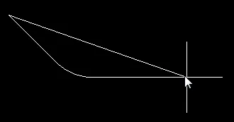
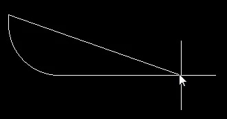
- Move the cursor ready to place the second vertex. The default behavior is to place two edges with each click, with a user-defined corner shape between them. Refer to the Placement Modes section below for more details on changing corner modes.
- Continue to move the mouse and click to place further vertices.
- After placing the final vertex, right-click or press Esc to close and complete the definition of the board shape. There is no need to manually close the board shape as the software will automatically complete the shape by connecting the start point to the final point placed.
Placement Modes
When redefining the board shape there are five available corner modes, four of which also have corner direction sub-modes. During redefinition:
- Press Shift+Spacebar to cycle through the five available corner modes: 45 degree, 45 degree with arc, 90 degree, 90 degree with arc, and Any Angle.
- Press Spacebar to toggle between the two corner direction sub-modes.
- When in either of the arc corner modes, hold the
 or
or  keys to shrink or grow the arc. Hold the Shift key as you press to accelerate arc resizing.
- For all corner modes except Any Angle, press the 1 shortcut key to toggle between placing two edges per click, or one edge per click. In this second mode the dashed edge is referred to as the look-ahead segment (as shown in the last image in the set below).
- Press the Backspace key to remove the last vertex.


 Press Shift+Spacebar to cycle through the five available corner modes, press the 1 shortcut to toggle placement between two edges or one edge
(for all modes except Any Angle).
Tips
- For a blank PCB project, or additional PCB documents added to an existing project, the default board shape is a rectangular shape (6Inch x 4Inch, or 6000mil x 4000mil, or 152.4mm x 101.6mm). For specific project templates that can be used when creating a new PCB project, the associated PCB document in each case has a specific board shape, according to the form factor of the board.
- To interactively modify the shape of the existing board - by moving vertices, or sliding the edges of the shape, rather than completely redrawing it anew - use the Edit Board Shape command. Alternatively, use the Modify Board Shape command.
