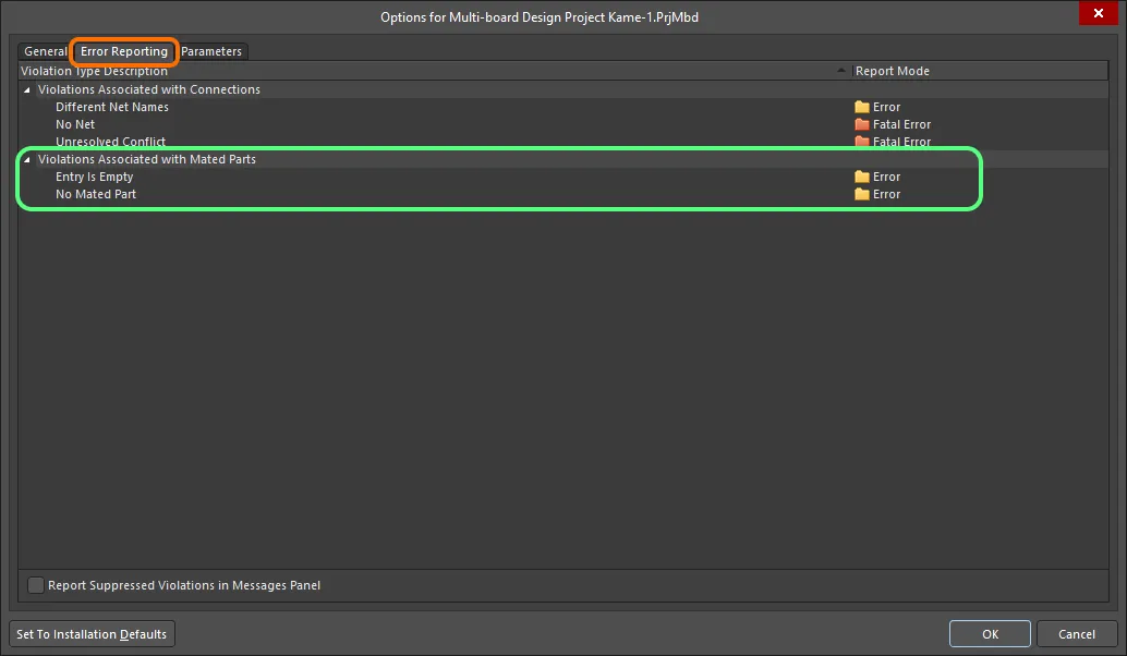
The Violations Associated with Mated Parts region on the Error Reporting tab of the Project Options dialog
Logical, electrical, and drafting awareness in the schematic diagram of your Multi-board Design project can be verified during design project verification according to rules defined as part of the options for the design project – on the Error Reporting tab of the Project Options dialog.
Violations associated with Multi-board Design projects are only presented after running an Electrical Rules Check (ERC) from the project's Multi-board Schematic document (*.MbsDoc). Do this by choosing the Design » Run ERC command from the main menu.
For more information about creating Multi-board schematics, see the Capturing the Logical System Design page.
The Violations Associated with Mated Parts region on the Error Reporting tab of the Project Options dialog allows specifying the severity level associated with check of violations related to mated parts that can exist in source documents when validating a Multi-board project. Use the following collapsible sections to access information on each violation available in this region.
Entry Is Empty
Default report mode: 
Summary
This violation occurs when a module entry does not currently reference a connector component in the child design project referenced by its parent module.
Notification
A notification is displayed in the Messages panel in the following format:
Entry "<EntryDesignator>" is empty in "Module <ModuleDesignator>(<ChildProjectName>)"
where:
EntryDesignator – is the designator of the offending module entry.ModuleDesignator – is the designator of the module on the Multi-board Schematic that is used to reference the child design project.ChildProjectName – is the name, including extension, of the child project referenced by the module.
Recommendation for Resolution
This violation can arise when:
- A connector component in the referenced child project and currently associated with an existing module entry has had its special
System:Connector parameter removed, and that change has been inadvertently imported to the Multi-board Schematic document. In this case, add the parameter back to the component then import the change back to the Multi-board Schematic document.
- A new entry has been placed manually within the parent module. In this case, import changes from the child project to synchronize the required entries with their underlying connectors then remove the redundant entry.
Typically, you would ensure that the connector(s) in the child project are placed and have been given the System:Connector parameter. Then use one of the Import from Child Project commands to have the entries automatically created in the empty/shell parent module referencing that child project. This is the quickest and safest method to have the module entries in the system-level design created in-sync with their underlying connectors in the child projects.
No Mated Part
Default report mode: 
Summary
This violation occurs when a module entry is not currently connected to another module in the design.
Notification
A notification is displayed in the Messages panel in the following format:
Part "<ConnectorDesignator>" (Entry <EntryDesignator>) doesn't have Mated Part in "Module <ModuleDesignator>(<ChildProjectName>)"
where:
ConnectorDesignator – is the designator of the connector component in the referenced child project.EntryDesignator – is the designator of the offending module entry (which is reflective of, and synchronized with, the underlying connector in the referenced child project).ModuleDesignator – is the designator of the module on the Multi-board Schematic that is used to reference the child design project.ChildProjectName – is the name, including extension, of the child project referenced by the module.
Recommendation for Resolution
Ensure that the offending module entry is connected to the required entry in a target module – making a connection between the connector on one child board with that on another. Choose the type of connection and wire it up between the two module's entries accordingly. Available connection types are:
- Direct Connection – a direct connection is used whenever the connector on one board is to plug in directly to the connector on another board without the use of a physical connection (wire, cable, or harness).
- Cable Connection – a cable is a physical connection, providing a conduit for net signals between two boards in a multi-board system, and that cable plugs into a connector on each of those boards.
- Wire Connection – a wire is a physical connection, providing a conduit for a single signal between two boards in a multi-board system, and that wire is attached directly into a connector on each of those boards. Although placing a single wire on the document, in reality, a series of wires will be used, in accordance with the number of signals/pins being connected between the connectors of the two boards.
- Harness Connection – a harness is a physical connection, providing a conduit for net signals between two boards in a multi-board system, and that harness plugs into a connector on each of those boards.
