The pages of preferences in the System category provide access to preferences relating to the system in general.
General
The System – General page of the Preferences dialog provides controls relating to the general settings of the software.
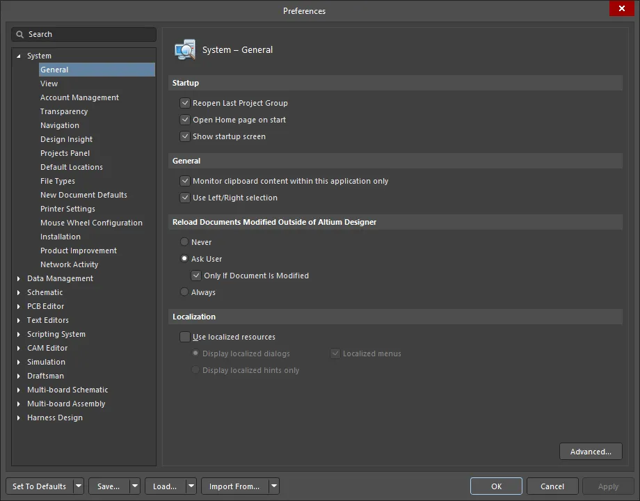
The System – General page of the Preferences dialog
Startup
-
Reopen Last Project Group - enable this option to open the last saved project group when the application is started. Disable this option to start a new project group session when the software is started up.
-
Open Home page on start - enable this option to display the Home Page when the application is started. Disable this option to not display the Home Page.
-
Show startup screen - enable this option if you want to see the startup screen when the software is being loaded into computer memory. This will provide visual confirmation that the software is loading. The startup process can take a while depending on whether previous project groups with projects are being opened or not. Disable this option to not see the startup screen.
General
-
Monitor clipboard content within this application only - enable this option to monitor the clipboard when copying and pasting data within the software. With this option enabled, non-compliant data that is copied to the clipboard will not be pasted within the software. Disable this option to not monitor the clipboard data.
-
Use Left/Right Selection - check to use right side (inside area) and left side (touching rectangle) selections in all editors. This option is enabled by default.
Reload Documents Modified Outside of Altium Designer
-
Never - select this option to never reload documents that have been modified outside of the software.
-
Ask User - select this option to ask the user for permission before reloading documents that have been modified outside of the software. Choosing this option will activate Only If Document Is Modified.
-
Only If Document Is Modified - enable this option to reload only modified documents. This checkbox is only accessible if Ask User is selected.
-
Always - select this option to always reload documents that have been modified outside of the software.
Localization
Use localized resources - localized resources are the installed local languages used for the software. The software platform supports simplified and traditional Chinese, Japanese, German, French, Korean, and Russian language installations. Click this option to enable localized resources for the software. Items will be translated according to the language that is installed on the machine on which the software is installed. A restart of the software is necessary if this option is selected.
By default, this option is disabled and standard English is the setting for all dialogs, menus, and hints.
The following options are available only if Use localized resources option is checked:
-
Display localized dialogs - choose this option to translate dialogs only.
-
Display localized hints only - choose this option to translate hints only.
-
Localized menus - enable this option to translate menus.
Additional Control
Advanced - click this button to open the Advanced Settings dialog to enable and disable internal optimization options.
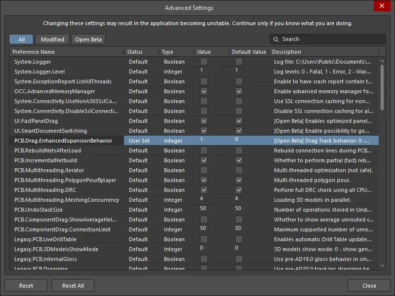
The Advanced Settings dialog
Changing settings in this dialog may result in software instability. Changes should be made with caution. In addition, if any changes have been made in the dialog, the software must be restarted in order for the changes to take effect.
Options and Controls of the Advanced Settings Dialog
View
The System – View page of the Preferences dialog provides controls relating to the look and feel of the general design space, including behavior of panels and documents.

The System – View page of the Preferences dialog
Desktop
-
Autosave desktop – enable this option to automatically save the position and size of document windows settings at shut down. The desktop includes the position and visibility of panels and toolbars.
-
Restore open documents – enable this option to open documents in the design space when the software is started according to their state in the previous session. Disable this option to start a blank design space when the software is started.
-
Layouts
-
Load - click to open a file browser to select a saved Desktop Layout (*.TLT) file.
-
Save - click to save the current layout as a Desktop Layout (*.TLT) file. Saved layouts can be loaded for re-use.
-
Reset - click to return to the default desktop layout configuration.
Popup Panels
-
Popup delay – move this slider to the right to maximize the time it takes for a panel to appear when in 'pop-out' mode. Move the slider to the left to minimize the time taken for the panel to appear.
-
Hide delay – move this slider to the right to maximize the time it takes for a panel to be hidden when in 'pop-out' mode. Move the slider to the left to minimize the time taken for the panel to disappear.
-
Use animation – enable this option if you want panels to be animated while they are being opened or closed in 'pop-out' mode. Disable this option if you want panels just to appear or disappear without any delay.
-
Animation speed – with the Use animation option enabled, move this slider to the left for slower animation or to the right for faster animation of panels in 'pop-out' mode.
General
-
Hide floating panels on focus change – enable this option to hide floating panels in the software when you are switching focus to a different software application. Disable this option to leave floating panels as they are when switching focus to another application.
-
Remember window for each document kind – enable this option to open documents in the same window or in individual windows in the specified locations according to the last placed document of the same kind. For example, when using two monitors, with this option enabled, you can open one schematic, drag it into a new window on the second monitor, and from then on all schematics opened will go to the second monitor. Disable this option to open documents of any kind in the same design space.
-
Auto show symbol and model previews – enable this option to automatically display Schematic symbol and PCB footprint graphics where they exist on the Components panel.
-
Open internet links in external Web browser – enable this option to have Internet-based content open as externally loaded content in your default Web browser.
Documents Bar
-
Group documents if need – enable this option to group documents together on tabs on the document bar. Grouped documents are indexed numerically in ascending order. Disable this option and all open documents will have their own visible tab on the documents bar. Two methods of grouping are available:
-
By document kind – enable this option to group documents of the same type on the same tab, with documents sorted alphabetically in a grouped tab.
-
By project – enable this option to group documents from the same project on the same tab, with documents sorted alphabetically within each document kind sub-group in a grouped tab.
-
Use equal-width buttons – enable this option to equally size all open document tabs, regardless how long the document filenames are. Disable this option and each document tab is resized according to the length of the document filename.
-
Multiline documents bar – enable this option if there are more document tabs that can fit on a single document bar. Disable this option and only one document bar can host document tabs.
-
Ctrl+Tab switches to the last active document – enable this option to toggle between the currently active document and the previously active document using Ctrl+Tab. Disable this option will toggle through all open documents sequentially when using Ctrl+Tab.
-
Close switches to the last active document – enable this option to make the last active document active again when closing the currently active document.
-
Middle click closes document tab – enable this option to close documents by using the mouse middle button (typically the Scrolling Wheel). You can then middle-click over a document tab to close that document.
UI Theme
-
Current - use the drop-down to select the desired user interface theme. Choices include: Altium Dark Gray and Altium Light Gray.
-
Preview - displays an example of the chosen theme in the above option.
Account Management
The System – Account Management page of the Preferences dialog provides controls to configure your Altium account. Altium Designer includes various on-demand style features, made available to you upon signing into your Altium account through the secure Altium portal. Such features include on-demand licensing, automatic software updates, retrieval of updated exchange rates for use with live links to suppliers, and streamlined activation of Standalone licensing. These features are all offered in accordance with a singular underlying vision - to enhance your productivity by delivering the information you need, when and where you need it.
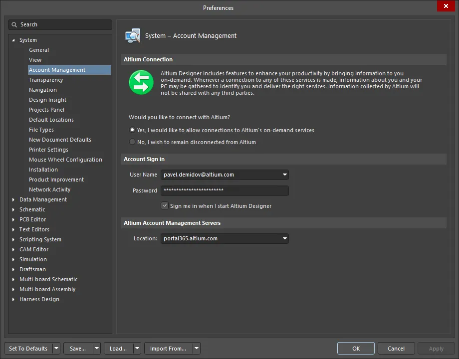
The System – Account Management page of the Preferences dialog
Altium Connection
Altium Designer includes features to enhance your productivity by bringing information to you on-demand. Whenever a connection to any of these services is made, information about you and your PC may be gathered to identify you and deliver the right services. Information collected by Altium will not be shared with any third parties.
Information Gathered
When you use a feature that connects Altium Designer to the on-demand services, Altium may collect the following information:
-
MAC Addresses: Altium uses a computer's MAC address to identify a PC. If you sign in on multiple computers, each sign in request will be recorded uniquely.
-
HDD serial numbers: Along with the MAC addresses, this information provides a robust way to identify a PC for licensing purposes.
-
Altium Designer version: Altium uses the software version to differentiate between products so that the correct services can be delivered for each product.
Altium does not, and shall not, read or gather any information about the designs or files you use within Altium Designer.
All connections to the Altium portal through Altium Designer are secure. Along with the information that is gathered, information that you enter will also be communicated in requests to Altium's portal. When data is recorded with Altium's portal, the data will include a time stamp showing when the data was recorded.
Altium's Privacy Policy
Altium is committed to ensuring that all the details you provide to us remain secure. The following privacy policy discloses the information practices for Altium services.
How we use the information
The information gathered by Altium is used to provide you with the correct services that can be delivered for your product. Altium may also use the information for internal reviews and analysis in order to improve our products and services.
We will not disclose your individual information to any third party and will not sell, trade or rent that information for marketing purposes. If we need to disclose any information to conform to any laws or legal process we will do so in a manner so as to provide the maximum amount of protection legally possible for such information.
Consent
By connecting with Altium's services through Altium Designer, you are consenting to the gathering of this information and our use of this information in accordance with the principles outlined in this Privacy Policy.
Should you not wish to receive the benefits that these services bring, Altium makes it readily possible to disconnect from its on-demand services.
If at any time we change the Privacy Policy we will post those changes on the website so that you are kept fully informed.
There may be occasions where you need to disconnect from these services altogether. For example, your company may have strict, non-negotiable policies in place for connection to the 'outside world'. In instances such as this, Altium makes it possible to disconnect from its on-demand services, placing full control in your hands. Should your circumstances change, you can reconnect with Altium at any time – on-demand!
Would you like to connect with Altium?
-
Yes, I would like to allow connections to Altium's on-demand services - by enabling this option you are allowing Altium Designer to connect with Altium over its secure portal whenever you want to access one of Altium's on-demand services. Enabling this option does not mean you are instantly and constantly connected to Altium, nor does it mean we are constantly gathering your information. Connection is only made at the time you actually use one of the on-demand-style features that require connection to Altium (through the portal). For example, to sign in to your account from within Altium Designer and manage extensions and updates, you use a feature that requires connection with Altium – which is only possible if you have enabled this option to allow such a connection. Data may be gathered at the time of using an on-demand service to ensure that you are provided with the right service for you.
-
No, I wish to remain disconnected from Altium - by enabling this option, your installation of Altium Designer will stay completely disconnected from Altium. While disconnected, you will not be able to access or use any of the on-demand services that require a connection with Altium. In essence, this option is a 'full off' switch, with the trade off of not being able to use any of Altium's on-demand services.
When the option to remain disconnected is enabled,

will be displayed and all other options on the page will be disabled.
If you are actively using a Standalone license, disconnecting from Altium will not affect the license since it is already activated and in use. Whether you are signed in or working offline with the license, simply disconnect and carry on working in true standalone fashion. If you are accessing your Standalone license for the very first time, or you have inadvertently deleted the license from your computer (and have no backup of the associated license file), you will need to activate (reactivate) the license. This can only be done while connected to Altium and signed in to your Altium Designer Account.
Use of Altium Designer Live Links to Supplier Data feature does not require you to be signed in to your Altium Designer Account since searching is conducted directly with the suppliers through web services. However, when displaying pricing information in alternate currencies, exchange rates for currency conversion are refreshed daily, provided you are signed in to your account. When you disconnect from Altium, access to these rates – which are updated every 24 hours – is lost.
While disconnected from Altium, you will not be able to utilize on-demand licensing, nor will automatic checking for updates be performed. All installation changes – and management of extensions – require that you be signed in to your Altium Designer Account.
Account Sign in
-
User Name - enter your user name in this field. This is the user name created when your Altium Designer Account Credentials were created.
-
Password - enter your Altium Designer Account password in this field.
-
Sign me in when I start Altium Designer - enable this option to automatically be signed in to your account when you start the software.
These settings are reflected in and are also affected by, changes made in the
Account Sign In dialog. The
Account Sign In dialog is accessed by clicking
Sign In on the
License Management page (Click the

button and select
License Management from the drop-down menu).
Altium Account Management Servers
When you sign in to your account, you do so through an Altium portal. On the Altium side, a portal is simply a secure connection to a specific Altium Account Management Server.
-
Location - enter the required portal. The default portal is portal365.altium.com.
Transparency
The System – Transparency page of the Preferences dialog allows you to control the transparency of floating windows and toolbars.

The System – Transparency page of the Preferences dialog
Transparency
-
Transparent floating windows - enable this option to automatically make all floating toolbars and windows that are over the design space transparent when an interactive process is invoked. If this option is enabled, the Files panel is made transparent.
-
Dynamic transparency - enable this option to dynamically set the transparency of floating toolbars and windows. The system uses the distance of each window from the cursor to calculate its transparency. If this option is enabled, whenever the cursor is moved toward a dialog, the dialog becomes transparent. Use the Distance factor slider to determine the distance at which the transparency 'kicks in'.
-
Highest transparency - move this slider to the right for maximum transparency whenever a cursor approaches the floating window.
-
Lowest transparency - move this slider to the right for minimum transparency whenever a cursor is moved away from the floating window.
Use the Highest transparency and Lowest transparency bars in conjunction with each other to control how transparent the windows and panels appear. For example, both bars to the far right means a floating window becomes completely transparent when an interactive process is in the way; both bars to the far left means the floating window is not transparent.
-
Distance factor - use this slider to determine the distance between the cursor and the floating window (dialog or panel) at which the transparency 'kicks in'. Move this slider to the left to set a smaller distance and to the right for a larger distance.
Navigation
The System – Navigation page of the Preferences dialog provides controls relating to navigating actions in the Navigator panel.

The System – Navigation page of the Preferences dialog
Highlight Methods
Select the desired methods of highlighting graphical objects during navigation, cross-probing, and when exploring differences between documents or compiler messages. Choose from the following:
-
Selecting - enable this option to select your item of interest.
-
Connective Graph - enable this option to show how your item is connected.
-
Include Power Parts - enable this option to show the connectivity through to the power parts as well in the connectivity graph. This option is only available if Connective Graph is checked.
-
Zooming - enable this option to zoom in to display your item of interest.
-
Far/Close - use this slider to control how closely the system will zoom into highlighted objects. The farther to the right (Close) you move the slider, the larger the magnification and vice versa.
-
Dimming - enable this option to dim the display of all other objects except your item of interest.
-
None/Invisible - use this slider to control the dimming. The farther to the right (Invisible) you move the slider, the more objects will be dimmed
Objects To Display
Enable the following objects you want displayed in the Navigator panel:
-
Pins
-
Ports
-
Sheet Connectors
-
Graphical Lines
-
Net Labels
-
Sheet Entries
-
Sheet Symbols
Cross Select Mode
Use the following options to cross select objects between the schematic and PCB.
-
Cross Selection - use to toggle cross selection on and off. When this is checked, each selected object in one editor will be selected in the open documents of the other editor.
-
Dimming - enable this option to dim the display of all other objects except the selected item(s).
-
Zooming - enable this option to zoom in to display your selected item(s).
-
Reposition selected component in PCB - enables you to select a component in the schematic and reposition it in the PCB.
-
Focus document containing selection if visible - enable this option to transfer focus to the schematic or PCB document that is visible when objects in them are cross selected.
-
Objects for cross selection - enable the required options you want to cross select: Components, Nets, and/or Pins. Any number of the options can be selected.
Design Insight
The System – Design Insight page of the Preferences dialog allows the user to control various aspects of design viewing, such as previews of documents, supply chain information, and hyperlinks.

The System – Design Insight page of the Preferences dialog
Design Insight
-
Enable Document Insight - check this option to display a preview of a document when you hover over the document icon in the Projects panel or document bar.
-
Enable Project Insight - check this option to display a table of document previews when you hover over the project icon in the Projects panel. Schematic, PCB and OpenBus documents are displayed. You can navigate to the document by clicking on it in the preview.
-
Enable Connectivity Insight - check this option to display the connectivity of net objects when you hover over a net object. Enabling this insight option will show previews of the child sheets for sheet symbols, net connectivity across the entire project for electrical objects, and sub-parts for components. The selected net is highlighted in the preview with all other objects masked. The previews will be displayed with respect to the project hierarchy. Use Alt+Double Click on any net object to show Connectivity Insight on demand. Compile the project to establish the connectivity information before using this feature.
-
Enable Hyperlink Insight - check this option to display a link over hyperlink objects, and annotations and parameters that have a URL or website as their text string.
-
Mouse Hover Delay - use the slider to control the delay for the Connectivity Insight information to appear, starting with 0s (seconds) on the left to a maximum of 4s on the right.
Connectivity Insight Options
Use this table to further customize Connectivity Insight.
Projects Panel
The System – Projects Panel page of the Preferences dialog provides controls relating to the behavior of the Projects panel.

The System – Projects Panel page of the Preferences dialog
General
-
Show VCS status – enable to show the status of the document in respect to the version control system (checked out or checked in).
-
Show document position in project – enable to show the document position relative to the project, indexed by a number in parentheses.
-
Show full path information in hint – enable to include full path information in the tip when the cursor hovers over a document name on the Projects panel.
-
Show Automatic Sheet Numbering – enable to display the automatic sheet numbering of documents in the Projects panel.
-
Show Components and Nets folders – enable to display the Components and Nets folders that list a PCB design project's components and nets upon validation of the project.
File View
-
Show Project Structure – enable to show the structure of intra-projects (consisting of sheets and sheet symbols) and inter-projects (connections between projects and the components that link them) if the File View option is selected on the Projects panel.
-
Show Document Structure – enable to show the structure of opened projects and sub-projects if the File View option is selected on the Projects panel.
Documents Grouping
-
Do not group – select this option if you do not want the project documents within a project listed as groups.
-
By class – select this option to list project documents in document classes: source documents, library documents and generated documents.
-
By document type – select this option if you want to group project documents according to their document type. For example, output documents will be listed under the Output Job Files folder.
Components Grouping
-
Do not group – select this option if you do not want the components within a project listed as groups.
-
By designator's first character – group components by the component designator's first character.
-
By comment – group components by their comments.
-
By owner sheet – group components by their owner sheets.
Sorting
-
Project order – select this option if you want project documents sorted according to the order they were added to the project.
-
Alphabetically – select this option if you want the project documents sorted alphabetically.
-
Open/modified status – select this option if you want the project documents sorted according to the status they are in, i.e. opened documents, edited documents, and unopened documents.
-
VCS Status – select this option if you want the project documents sorted according to whether they are logged as checked out, checked in or as standalone documents from a version control system.
-
Ascending – enable if you want the project documents to appear in ascending order.
Single Click
-
Does nothing – select this option to cause a single click on the Projects panel to do nothing.
-
Activates open documents / objects – select this option if you want a single click on a document in the Projects panel to bring to the front a currently open design document.
-
Opens and shows documents / object – select this option if you want a single click on a document in the Projects panel to open this document in the design space.
Default Expansion
Any changes made to the Default Expansion settings require a reboot of the system for the changes to take effect.
-
Fully contracted – select this option to show only project titles.
-
Expanded one level – select this option to show only projects and their top-level documents.
-
Source files expanded – select this option to show only source documents (such as schematic documents) of a project. Other document types, such as output job files and database link file folders will remain contracted.
-
Fully expanded – select this option to show all files of open projects.
Default Locations
The System – Default Locations page of the Preferences dialog allows you to specify default locations for your documents, libraries, and output job files.
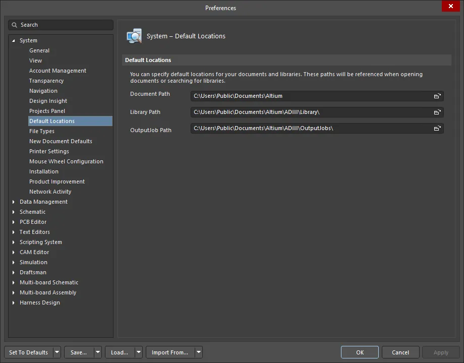
The System – Default Locations page of the Preferences dialog
Default Locations
-
Document Path - use
 to open a dialog to search for and choose the desired default document path.
-
Library Path - use
 to open a dialog to search for and choose the desired default library path.
-
OutputJob Path - this is the location for default Output Job files that can be added to a project when using the Project Releaser if that project currently has no Output Job file(s) associated with it. By default, two files are provided with the installation (Fabrication.OutJob and Assembly.OutJob). You can run with these default files as they are, edit them to suit your needs, and add additional Output Job files. Define the Outjobs as required within the default folder or specify your own custom folder location by using
 to open a dialog to search for and choose an alternative folder location. All Output Job files found in the specified location will be added to the project.
File Types
The System – File Types page of the Preferences dialog allows you to define the file types associated with the software.

The System – File Types page of the Preferences dialog
Associated File Types
-
Supported Extensions - this region is a list of all the file types supported by the software.
-
Register - associate the file type by checking the box.
-
Extension - the extension of the file.
-
Description - a description of the listed file.
-
All On - click to check all file types.
-
All Off - click to uncheck all file types.
-
Group on - click to check all file types within a group once a file type is selected.
-
Group off - click to uncheck all file types within a group once a file type is selected.
-
Selected on - click to check the box of a selected file type.
-
Selected off - click to uncheck the box of a selected file type.
New Document Defaults
The System – New Document Defaults page of the Preferences dialog leads to the Data Management - Templates page of the Preferences dialog, where you can manage templates from one place.
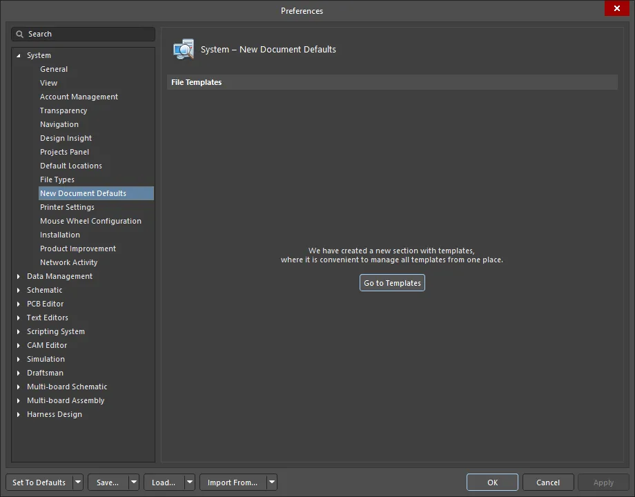
The System – New Document Defaults page of the Preferences dialog
File Templates
Go to Templates - click this button to access the Data Management - Templates page of the Preferences dialog.
Printer Settings
The System – Printer Settings page of the Preferences dialog allows you to customize page sizes for exported PDF documents.
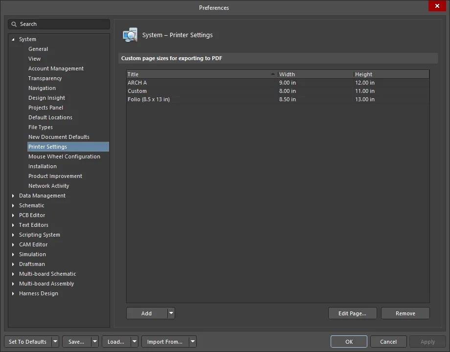
The System – Printer Settings page of the Preferences dialog
Custom page sizes for exporting to PDF
-
Grid
-
Title - the name of the page size.
-
Width - the width of the page size.
-
Height - the height of the page size.
-
Add - click to add a size to the main list. Choices include:
-
ARCH A
-
ARCH B
-
ARCH C
-
ARCH D
-
ARCH E
-
ARCH E1
-
C5 Envelope (162 x 229 mm)
-
DL Envelope (110 x 220 mm)
-
Folio (8.5 x 13 in)
-
JIS B1
-
JIS B2
-
JIS B3
-
JIS B4
-
JIS B5
-
Ledger (17 x 11 in)
-
Monarch Envelope (3.87 x 7.5 in)
-
No. 10 Envelope (4.125 x 9.5 in)
-
Note (7.5 x 10 in)
-
Statement (5.5 x 8.5 in)
-
Custom - click this choice to add a new page title and size.
-
Edit Page - click to open the Edit Page dialog in which you can customize the title and size of the selected page size.
-
Remove - click to remove the selected page size from the list.
Mouse Wheel Configuration
The System - Mouse Wheel Configuration page of the Preferences dialog is used to configure how the mouse wheel functions. You can configure the mouse wheel functioning for all editors or specifically for PCB and/or schematic documents.
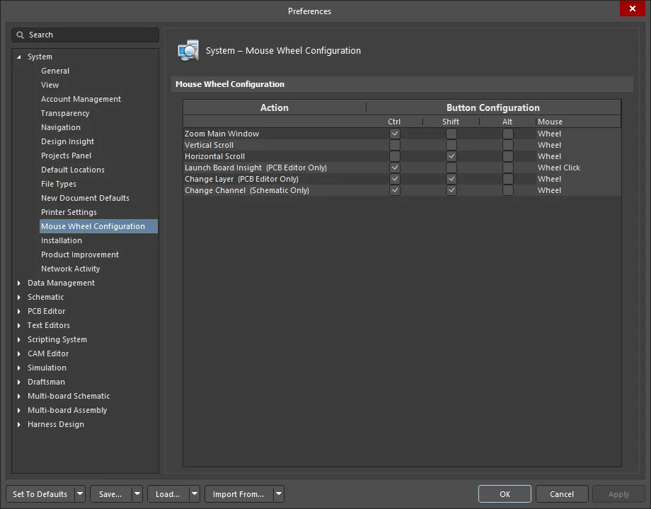
The System – Mouse Wheel Configuration page of the Preferences dialog
Mouse Wheel Configuration
-
Action - a list of actions for which the mouse wheel can be configured. These configurations are for a mouse that has a wheel between two mouse buttons. As noted in the grid, Launch Board Insight and Change Layer are configurations that affect the mouse wheel only in the PCB Editor; Change Channel affects the mouse wheel only in the schematic.
Action items that do not specify an editor will configure mouse wheel operations in all editors, with the exception of the CAMtastic editor.
-
Button Configuration - use these options to configure any keyboard button combination (Ctrl and/or Shift and/or Alt) that is required to be used along with the mouse wheel function (as listed in the grid) to perform that action.
Installation
The System – Installation page of the Preferences dialog provides controls relating to updating the installation of the software.
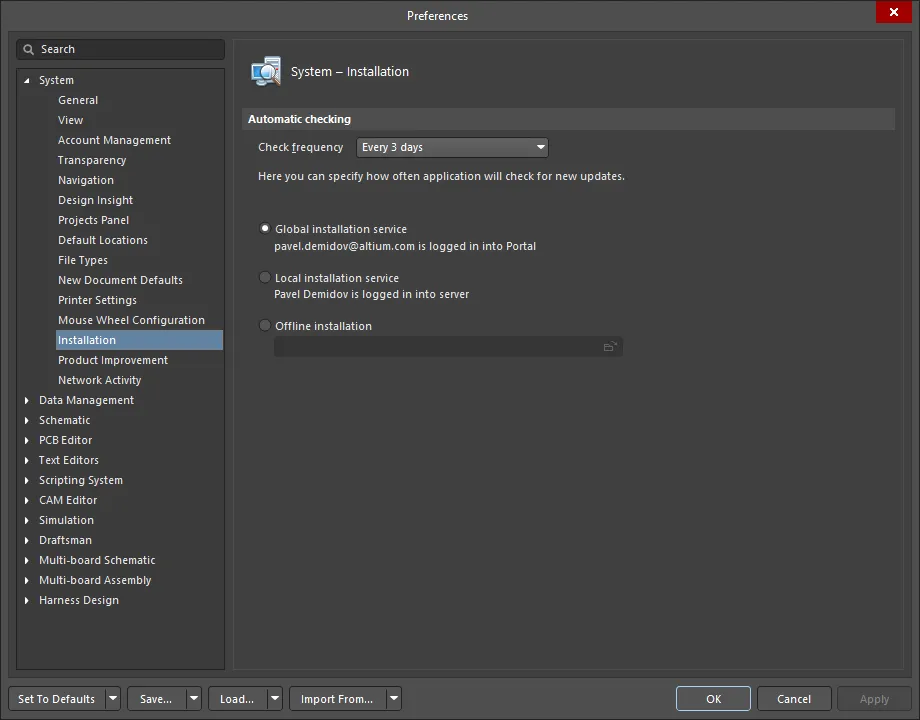
The System – Installation page of the Preferences dialog
Automatic Checking
-
Check frequency - use the drop-down to select how often you want the system to automatically check for updates. Choices include:
-
Never
-
On Start-up
-
Every day
-
Every 3 days (Default)
-
Every week
-
Every 2 weeks
-
Every month
-
Global installation service - select this option if you use global installation services.
-
Local installation service - select this option if you use local installation services.
-
Offline installation - use
 to open a dialog to search for the desired folder for offline installations.
Product Improvement
The System - Product Improvement page of the Preferences dialog allows you to opt in or out of Altium's Product Improvement Program. This program helps Altium to improve Altium Designer moving forward by better understanding user behavior and environments. You can commence (or stop) participation at any time. Rest assured that no personal data or design/IP information will be collected by participating in this program. Participation in this program is strictly voluntary and anonymous and you are free to stop participating in the program at any time. For the rules that govern the program, click the Read Altium's Privacy Policy link to see the Altium Designer Improvement Program page on the Altium site.

The System – Product Improvement page of the Preferences dialog
Why Should I Participate?
Similar programs are now standard in the software development industry by companies such as Microsoft®, Google®, Apple®, etc. It is likely that you already share your user experience with any number of companies. Your participation in this program will give Altium the ability to fine-tune our products for your specific environment, identify issues you face during your everyday work, and to improve Altium Designer to fit your needs.
What Type of Data is Collected?
Some examples of statistical information we collect include but are not limited to:
-
Number of outjob files in projects
-
Number of pins in a typical board
-
Types of installed libraries
-
Most frequently used commands
-
Duration of full project compilation
-
Load times for files.
A few examples of hardware information we collect includes, but is not limited to:
-
Number of CPUs and monitors
-
Screen resolution
-
OS platform and version
How is Information Collected?
Information about your computer hardware and how you use Altium Designer will be sent periodically to Altium's servers for analysis.
The data collection process will not affect your computer or designs in any way. A highly optimized approach to data collection is employed, which has no detrimental effect on your computer's performance.
How will the Information be Used?
The following are just some of the ways in which information obtained and assessed through user participation in the program will be used:
-
Identify the most popular features so that focus can be given to their improvement.
-
Optimize UI for more commonly used hardware.
-
Locate performance obstacles in the software.
-
Ensure productivity features are being used.
-
Retire unused features.
Network Activity
The System - Network Activity page of the Preferences dialog gives you full control over network connectivity. Altium Designer uses the Internet and third party servers to connect to Altium Cloud and suppliers, to search for updates, etc. It may be desired or necessary to work offline in some situations or environments. You can disable specific network activity or disable all network activity by selecting/deselecting the listed functions on this page.
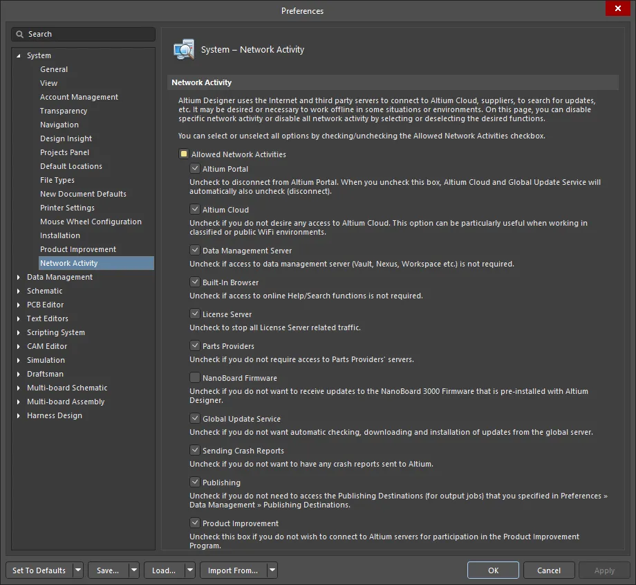
The System – Network Activity page of the Preferences dialog
Network Activity
Allowed Network Activities - click to check/uncheck each activity from which you wish to connect/disconnect:
You can also fully disable all network connectivity by clicking Allowed Network Activities (at the top of the list) to uncheck all boxes. To reconnect to all listed options, click Allowed Network Activities again to recheck all boxes.
Altium Designer must be restarted for any of the new Network Activity settings to take effect.
-
Altium Portal - check this box to connect to the Altium Portal. When you uncheck this box, Altium Cloud and Global Update Service will automatically also uncheck.
-
Altium Cloud - check this box to have access to Altium Cloud. Unchecking this option can be particularly useful when working in classified or public WiFi environments.
-
Data Management Server - check this box if access to a connected Workspace is required. If disabled, you will also be disconnected from the Infrastructure server for licensing.
-
Built-In Browser - check this box if access to online Help/Search functions is required.
-
License Server - check this box to allow all License Server related traffic.
-
Parts Providers - check this box if you desire access to Parts Providers' servers.
-
NanoBoard Firmware - check this box if you want to receive updates to the NanoBoard 3000 Firmware that is pre-installed with Altium Designer.
-
Global Update Service - check this box to allow automatic checking, downloading and installation of updates from the global server.
-
Sending Crash Reports - check this box if you want to have crash reports sent to Altium.
-
Publishing - check this box to access the Publishing Destinations (for output jobs) that you specified in the Data Management - Publishing Destinations Preferences page.
-
Product Improvement - check this box if you want to connect to Altium servers for participation in the Product Improvement Program.