In a nutshell, Project Management is focused on securely storing and tracking changes throughout the design process, and ultimately, channeling the resulting design through to the creation of a physical item – such as an assembled PCB to be used in the final product. To meet these needs, Altium Designer provides a range of project management approaches that offer increasing levels of sophistication and capabilities, yet simplify the process from a designer's perspective. These range from local file-based storage and management, to local/remote Version Control System (VCS) storage approaches, and through to its advanced and recommended form where the management of design data is centered on the capabilities of a server-based Altium Workspace.
A connected Altium Workspace and its internal VCS service hosts and manages Altium Designer projects, and also provides simplified VCS operations, inherent design collaboration capabilities, advanced design data sharing, history tracking, Lifecycle management, and much more. Projects that are integrated with a Workspace are accessed directly from Altium Designer, such as from the Projects or Explorer panels, or from the Workspace itself through its browser-based interface.
Thanks to the intelligence built into the services provided by a Workspace, tasks such as VCS operations are simplified and automated, and additional design collaboration features such as user access control (sharing), commenting and history are available directly from within Altium Designer. The end result is a robust and secure project storage format and location that can become the central point for collaborative project design.
Altium Designer can connect to a Workspace based on a choice of platform formats:
- A Workspace provided by the Altium 365 platform – this delivers the accessibility and reliability advantages of a remote server platform that is managed and updated by Altium, and also offers a tightly-controlled design data sharing system that enhances Project design collaboration.
- A Workspace provided by a local server, such as Altium Concord Pro – this Workspace offers most of the features of an Altium 365 Workspace, but is constrained to your local network and managed by your company. Projects can be shared only between the local Workspace users, but fixed snapshots of a design can be shared externally through the Altium 365 platform. See Sharing a Design Snapshot for more information.
The Altium NEXUS solution is comprised of the Altium NEXUS design client and a Workspace provided by the Altium NEXUS Server. The Altium NEXUS Server is considered as an on-site server, as opposed to the Altium 365 Platform that is accessed via the internet.
The NEXUS Server Workspace integrates with the NEXUS design client over your local network and allows projects to be shared between local Workspace Users. Also, if internet connectivity is available, fixed snapshots of a design can be shared externally through the Altium 365 platform. See Sharing a Design Snapshot for more information.
This document takes a look at working with managed projects from Altium Designer, including:
- Creating a Project – either directly or by making an existing, unmanaged project available online.
- Sharing a Project – changing the access permissions for a project so that users that need to see and work with it have the ability to do so.
- Opening a Project – to be able to work on it.
- Cloning a Project – to quickly get an identical copy without having to build the project from scratch, which is great if your next project is very similar.
- 'Soft' Deleting a Project – removing an entire project to the Workspace Trash location, which has the options to permanently delete the project or restore it to its previous location.
- Commenting a Project – placing tagged notes on a document that are stored in the Workspace and available to all uses that have access to that project document.
- Releasing a Project – sending project data as manufacturing packages to the connected Workspace, which can be shared with others such as your PCB project Fabrication and Assembly service.
- Viewing Project History – browsing a progressive timeline of major events relating to the project – its creation, commits, releases, clones and MCAD exchanges – with various actions supported where applicable.
Creating a Project
There are two ways in which a managed project can be created from within Altium Designer:
- Creation of a new project through the Create Project dialog.
- Making an existing, local project (or a local project currently under external version control) available to a Workspace.
Types of Projects that can be created
PCB Project
In a Printed Circuit Board (PCB) project, the electronic circuit is captured as a schematic, which is built up from libraries of component symbols that are placed and wired together.
The design is then transferred to the PCB editor where each component is instantiated as a footprint (pattern) and the circuit wiring becomes point-to-point connection lines. A shape for the final PCB is defined, along with the physical layers the board will include. Design rules specify the layout requirements, such as routing widths and clearance. The components are positioned within the board shape, and the connection lines are then replaced by routing, either manually or automatically.
When the design is complete, standard format output files are generated which can be used to fabricate the blank board, configure an assembly machine, and so on.
Projects that are stored and managed in a Workspace are shown with an indicative icon, such as

for a PCB project.
Multi-board Project 
In a Multi-board project, the logical design is captured using a schematic document that connects together sub-project modules, which in turn represent existing PCB projects. The Multi-board schematic data is then transferred to a Multi-board assembly document where the physical board assemblies, as defined by the sub-projects, are positioned together and within an added enclosure.
A Multi-board project (*.PrjMbd) effectively defines the electrical and physical connectivity between existing PCB design projects through the application of a logical schematic document (*.MbsDoc ) and synchronized assembly document (*.MbaDoc).
► Read more about Multi-board Projects.
Integrated Library 
An Integrated Library is created in a library package project (*.LibPkg), where schematic symbols are created in a Schematic Library (*.SchLib), and reference links defined to matching models in other domains. Referenced models can include PCB footprints, circuit simulation models, signal integrity models, and three-dimensional mechanical models.
Files that contain the models (PCBLibs, etc) are added to the Integrated Library Package (*.LibPkg), or search paths are defined to identify their location. The source schematic symbol libraries and required models are then compiled into a single file (*.IntLib), referred to as an Integrated Library.
A better and far more advanced solution to managing design component data is where Components are hosted in and sourced from an Altium Workspace. An Altium Workspace provides secure high-integrity storage for component data, with the added benefits of lifecycle management and up to date supply chain information.
► Read more about Managed Components.
Script Project 
A Script (*.pas) contains a set of instructions (automated commands) that are interpreted when it is executed in Altium Designer. The scripts are written and debugged in the same editor environment.
There are two types of Scripts – script units and script forms. A script Unit can use the X2 Application Programming Interface (API) to modify or manipulate design objects on a design document. A script Form hosts controls as a user interface and harnesses the X2 API to provide script dialogs that act on active design documents.
Script Units, Forms and Data Models are contained in a Script project (*.PrjScr).
The following sections take a closer look at creating a new project, and converting an existing local project to a Workspace-based project.
Through the Create Project Dialog
A new managed project can be created from within Altium Designer using the Create Project dialog (File » New » Project):
 Setting up the Create Project dialog to create a new managed project from within Altium Designer. Note that the Advanced options will be appropriate by default.
- In the Locations list, select the entry for your Workspace (it will appear with the name defined for it) – you must be actively connected to the Workspace to see this option in the listing. This will be the target server in which to store your new managed project.
- In the Project Type list, choose the type of project you wish to create, and choose from the applicable templates available as required. If you have project templates created and released into your Workspace, these will appear listed as the only available templates from which to choose. The <Empty> entry will create a shell project with no initial source documents.
- Enter a Project Name and optionally, a project Description.
-
The project name should start with, and can contain A-Z, a-z, or 0-9. Underscores, dashes, and spaces are allowed, but the latter can only be used within the middle of the name (leading and trailing spaces will be ignored). You can not use the following words: AUX, COM1-COM9, LPT1-LPT9, CON, NUL, and PRN. In addition, the name cannot contain the following characters: \ . / ? % * : | " < >.
The Create Project dialog includes further options:
- Check the Version Control option (the default) to impose all VCS capabilities on the project, such as history and advanced sharing capabilities. When unchecked, the project is stored in the Workspace and synchronized with the local copy – a 'mirrored' project in the Simple Sync format. ► More information.
- Click the Advanced control to specify folder paths.
- Use the Folder field to specify where the folder for the project – within the Workspace's folder structure – is to be created. The default path for new projects is specified on the Admin – Settings – Projects page of the Workspace's browser interface (by default, this will be
Projects\<ProjectName>). Click the  button to browse to and select a different server folder, if required.
- Use the Local Storage field to specify where the local version of the project will be stored on your hard drive. The default location is defined on the System – Default Locations page of the Preferences dialog. Click the
 button to browse to and select a different folder location, if required. This is the 'working' folder for the project and the local Git repository it is committed to. The project is ultimately, or at the time of committal, pushed to the centralized design repository in the Workspace (Versioned Storage), which is the remote Git repository.
- Use the Parameters list area to add or remove custom Name/Value parameter pairs that are associated with the project and saved in the Workspace. Use the
 button to add a new parameter Name-Value pairing to the list. These managed project parameters are saved in the Workspace with the new project, and can be edited within the Workspace. By contrast, Project type parameters are saved in the project file (
*.PrjPcb), and can be edited in Altium Designer. Both parameter types may be used as Special Strings in Altium Designer – access from the Properties panel with a placed Text String selected in the design workspace. Parameters defined for the project can also be viewed on the Parameters tab of the Project Options dialog (Project » Project Options).
With the project defined as required, click the  button. The new project structure will be created in the specified local and Workspace (server) folders. The project will be opened in the Projects panel, which will reflect the fully synchronized state that exists between the files in the remote design repository (in the Workspace) and the local (working copy) repository – as indicated by the associated
  icons. If created with the Version Control option unchecked (available in an Altium 365 Workspace only), the mirrored project will be shown in the Projects panel with an associated
  icon.
icon.
 The newly created project committed to the Versioned Storage design repository in the Workspace.
- The project will appear in the Projects panel under an entry for the target Workspace, reflecting the name of that Workspace.
- In addition, an entry for the project will appear on the Projects page of the Workspace's browser interface.
- The project will initially be shared for Read/Write access with the designer who created it (Owner), and all Administrators for the Workspace.
► See Sharing a Project for more information on configuring project access permissions.
- A new project also can be created directly in a Workspace through its browser interface on the designs page (select Projects), and subsequently opened for editing and addition in Altium Designer.
Project Options
An existing or newly created Project is associated with a range of Option settings that are specific to that project. These are stored in the project file (*.PrjPcb, for example) and will vary depending on the type of project. Note that Server Parameters are stored with the project in its Altium Workspace.
The option settings are configured in the Project Options dialog, which can be accessed from Project » Project Options on the main menu, or by right-clicking on the project name in the Projects panel and then selecting Project Options from the context menu.
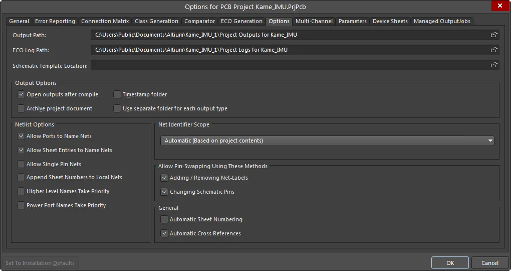
Other project settings that are defined in other dialogs and then stored in the project file include:
- Schematic annotation settings.
- Output settings such as; reports, print, Gerber, and so on. Note that these are the output settings accessed via the schematic or PCB editor menus, rather than the output settings defined in an OutJob document.
Project Groups
In Altium Designer you can open and edit multiple projects, and if desired, save the collective set of projects as a Project Group (
*.DsnWrk).
This can be of particular advantage when the set of projects are related or linked, such as a product design that is composed of multiple PCBs. Creating a Project Group that includes all the relevant projects allows you to open, manipulate, and save multiple projects as a single entity.
More on using Project Groups
- The current Project Group is listed along with open projects in the Projects panel – either the default one (
Project Group 1.DsnWrk), or one you have created or opened.
- To save the currently opened set of projects as a group select File » Save Project Group As from the main menu.
- To open an existing group, select File » Open Project Group from the main menu, or right-click in the panel and select Open Project Group from the context menu. Use the same access for the Save Project Group command.
- To close a Project Group, select Window » Close All from the main menus.
- To close all documents in a Project Group, select Window » Close Documents from the main menus.
- To create a new Project Group, select File » New » Design Project Group from the main menu – this will load the default (blank) Project Group (
Project Group 1.DsnWrk). The same method can be used to close the current Project Group file.
- Only one Project Group can be open at a time, so when opening a different Project Group the current group will close. You will be prompted to save any unsaved documents, projects or changes to the current group first.
- To add another project to a Project Group, open or create a project and then save the current Project Group. Alternatively, right-click in the panel and select the Add Existing Project option.
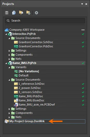
Work with a set of related projects as a Project Group.
Make an Existing UnManaged Project Available Online
You can also make an existing project (a local project, or a local project currently under external version control) available to the Workspace – either as a project mirrored (Simple Sync) in an Altium 365 Workspace, or one under a Workspace's native Git Version Control. This allows you to benefit from the project management and collaborative features available through an Altium Workspace, or when also hosted in the Workspace VCS (Version Control enabled), benefit from the platform's additional features such as History tracking and advanced project Sharing.
To do this, open the existing unmanaged project as normal in Altium Designer, then right-click on its entry in the Projects panel and select Make Project Available Online from the context menu, giving access to the Make Available Online dialog. When using a Workspace provided by an on-site server such as Altium Concord Pro, the Make Project Available on Server command opens the Make Available On Server dialog.
 Make an existing unmanaged project available to the Workspace, essentially 'registering' it with the Workspace and creating a 'mirror' of it.
Use the Make Available Online dialog to change the project Name and add a Description. By default, the name will be that of the original project.
Check the Version Control option to add the project under the Workspace's own built-in VCS (Git). When this option is unchecked (an Altium 365 Workspace option only), the project files will simply be stored in the Workspace for basic access and to enable sharing with others for viewing and commenting only – the Simple Sync arrangement. It is recommended to enable formal version control, as by doing so you will have access to the maximum functionality offered through, and by, the Workspace and the Altium 365 platform.
If the unmanaged project is already under version control (an external design repository) the Version Control option will be enabled and grayed out, with text highlighting that your project is already under version control. That is to say, it will remain under the external VCS design repository, and not be added to the Workspace's own built-in VCS (Git) design repository. Simple Sync applies, but multiple collaborators can continue to work on/edit the design, since it is under VCS.
Project Sharing in an Altium 365 Workspace:
If the Version Control option is disabled – thereby using the informal Simple Sync feature for an unmanaged project (that is not under external VCS) – the design project can be edited by a single person only (the owner of that project, who is the one that made it available online to the Workspace). The strength of Simple Sync comes when you do not want anyone else editing your design, but where you do want to take advantage of Altium 365's Global Sharing paradigm, and be able to share that design with multiple other people for viewing and commenting.
When the Version Control option is enabled – through the use of the Workspace's Versioned Storage Git-based design repository – then multiple people can be shared the project for editing, or for viewing and commenting.
Click the dialog's Advanced link to expose the Folder field. This field is used to specify where the folder for the mirrored project – within the Workspace's folder structure – is to be created. The default path for new projects is specified on the Admin – Settings – Projects page of the Workspace's browser interface (by default, this will be Projects\<ProjectName>). Click the  button to browse to and select a different server folder, if required.
Note that ability to mirror a project in a Workspace (Simple Sync) is available only when connected to an Altium 365 Workspace.
With the properties for the project transition defined as required in the Make Available Online dialog, click OK. Projects that have been made available online – in the Workspace – will be shown in the Altium Designer Projects panel as follows:
- (Altium 365 Workspace only) For a project that is not under external version control and made available online with the Version Control unchecked, the project is shown with the
 icon only. This indicates the project as being registered with the Workspace, that a mirrored project exists, and that the two are synchronized using the Simple Sync methodology. Saved local files are automatically synchronized with their mirrored project counterparts in the Workspace.
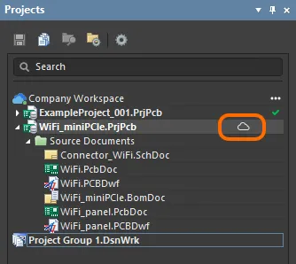
- (Altium 365 Workspace only) For a project that is under external version control, the project is shown with the
 icon to indicate the project as being registered with the Workspace, that a mirrored project exists, and that the two are synchronized using the Simple Sync methodology. Associated
  icons reflect the fully synchronized state that exists between the external design repository and the local working copy. Once local file changes are saved and committed/pushed to the external design repository, those changes are automatically synchronized with their mirrored project counterparts in the Workspace.
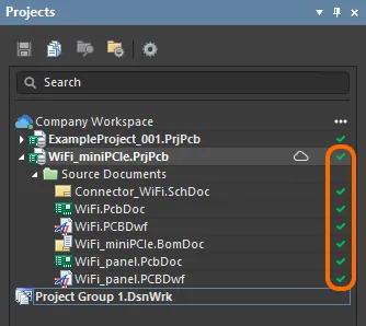
- For a project that is not under external version control and when made available online (in an Altiium 365 Workspace, the Enable Formal Version Control was checked), the project and files will be committed and pushed to the Workspace's Versioned Storage design repository. The Projects panel will then reflect the fully synchronized state that exists between the Workspace design repository and the local (working copy) repository, as indicated by the associated
 icons. The project becomes a true managed project – not just 'registered' in the Workspace, but actually committed and under the Workspace's version control. Any changes made to the design must be saved (committed/pushed) back to the repository in the Workspace.
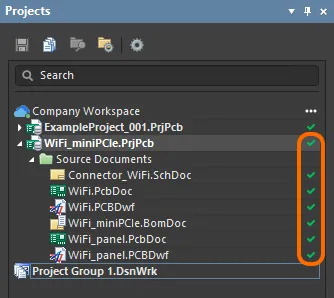
The new Workspace project will initially be shared for Read/Write access with the designer who created it (Owner), and all Administrators for the Workspace. For more information on configuring project access permissions, see
Sharing a Managed Project.
Simple Sync States
Where a local project is made available online to an Altium 365 Workspace using the Simple Sync approach (not using the Workspace's formal version control), the current state of the synchronization between local and server-side projects is presented in the Projects panel through a range of icons – note that the simple synchronization (mirroring) approach is available only when connected to an Altium 365 Workspace. The icons, and their meaning, are as follows:
 |
Synchronized |
The local project and the mirrored project in the Workspace are synchronized. |
 |
Sync-in-progress |
Changes made to the local project are being synchronized to the mirrored project in the Workspace. For a local project not under external VCS, this occurs when saving a local file. For a local project under external VCS, this occurs when saving and committing local file changes to the external design repository. |
 |
Project is Read-only |
The project has been shared with you, but you have Read-only access to it. Under the Simple Sync methodology, the design project can be edited by a single person only (the owner of that project – the one who made it available online to the Workspace). |
 |
Not Synchronized |
Changes have been made locally, but these have not been synchronized yet with the mirrored project in the Workspace. This can happen, for example, when the same project is open for editing by the owner/author on two computers (PC1 and PC2). On PC1, the Workspace is subsequently disconnected. On PC2, connection to the Workspace remains and changes are made. On saving the local file(s) the project remains unsynchronized. If you attempt to close the project on PC2, the Closing unsynchronized projects dialog will appear alerting you to this fact. If you choose to close the project, changes will not be available on PC1. To remedy the situation, disconnect from and then reconnect to, the Workspace on PC2. The project will be synchronized with the Workspace. The synchronized data will be reflected on PC1 once the Workspace is connected there too. |
 |
Conflict |
There is a conflict between the data for the local project and the data for the mirrored project in the Workspace. This can happen, for example, when the same project is opened for editing by the owner/author on two computers (PC1 and PC2). On PC1, the project is opened and the Workspace subsequently disconnected. Changes are then made and local files saved. Later, on PC2, the same project is opened and, while still connected to the Workspace, changes are made and saved. Later still, connection is made to the Workspace back on PC1. A conflict exists because there are changes locally on PC1, but the Workspace contains the updated data from changes made and synced on PC2.
To remedy the situation, on PC1 right-click on the project and choose the Resolve Conflicts command. The Resolve Conflicts dialog will appear. You have the option to Use Server files (the data from the mirrored project in the Workspace will be used and local modifications will be lost), or Use Local files (the data from the local project will be used and synced to overwrite the current data for the mirrored project in the Workspace).
|
Limitations when using an Existing External Version Control Repository
As mentioned previously, your local designs may already be tracked under an existing, external version control system (Git, SVN, EPDM, etc...). When using an Altium 365 Workspace, you can continue using this setup as before and simply make the designs available to your Workspace by registering them with that Workspace – using the Make Project Available Online feature.
In this mode, every time you make changes to a design and commit those changes to your external VCS repository, that design data will be mirrored to the Workspace in the background, and all needed processing will be performed as usual – preview, where used etc. There are some limitations to be aware of however:
- Creation of a new design project still has to follow the previous flow, that is, it is manually created in the external VCS system. The project is then registered and mirrored to the Workspace using the Make Project Available Online feature.
- If design changes are made but the commit/push is performed by external tools rather than through Altium Designer, then those changes will not appear for the mirrored project in the Workspace. This is corrected when the project is next reopened in Altium Designer, which automatically synchronizes the local project with the mirrored Workspace version. If the changes were made by another user, then the reopened project file(s) will show as
Out Of Date ( ) and can be corrected using the version control Update command.
- Opening of the project by a second person will require access to that external VCS repository.
- Rights management will have to be setup/maintained in two places – in the Workspace and in the master source (the external Git/SVN/etc VCS repository).
- Some features delivered through the Altium 365 platform work only by having a project under the Workspace's native version control system. By keeping your project under an external version control system such features, as they become available to the platform, will not be available to you. You can move from using your external VCS to the Workspace's native VCS – see this following section for the procedure to achieve this.
Working with GitHub
Using the GitHub platform as an external version control system (VCS) is a popular way to host and share design projects, and Git repositories are supported by Altium Designer. As described above for an Altium 365 Workspace, the existing external VCS arrangement can be synchronized with (mirrored to) the Workspace, which allows you to benefit from its advanced data management and collaboration features.
How you normally work with GitHub itself will vary depending on company practices or simply the Git tools you have at hand. In general however, a design project is created in a local Git repository and then Pushed to a GitHub (remote) repository, or an existing project is Cloned to a local repository from GitHub. Once in the local Git repository, the project can be opened in Altium Designer for editing – the software will recognize and use the local/remote GitHub repositories.
If the Git-based project is mirrored to an Altium 365 Workspace (Make Project Available Online), the project can be managed and worked within Altium Designer like any other project stored in the Workspace. In this arrangement the Workspace still provides all the advantages of its project management system and also transparently communicates with GitHub to perform the major VCS actions – commit, push, pull, etc. Altium Designer will request your GitHub login credentials and retain these for subsequent GitHub interaction.
Note that Altium Designer is not able to connect with GitHub automatically if the GitHub account has been configured for
two-factor authentication.
GitHub Protocols
While there is a range of data transfer protocols offered by the Git VCS, Altium Designer currently supports the HTTP/HTTPS protocol only for connections between a local Git repository and its remote master repository. In practice, the applied protocol is set by the URL prefix specified for the remote repository connection – https://<remote repository>, ssh://<remote repository>, git://<remote repository>, and so on.
GitHub supports both the SSH and HTTPS protocols, and recommends using HTTPS URLs for connections.
► See Which remote URL should I use? on GitHub for more information.
The HTTPS protocol offers the advantage of a secure connection that is simple to use and implement, whereas SSH is more complex to deal with – due to the need for public keys, firewall/proxy port requirements – is arguably less secure, and does not provide the convenience of SSO (single sign-on) authentication.
Similarly, the GIT connection protocol is not recommended (or supported here) due to its lack of authentication and setup complexity.
If your external VCS system is bound to a protocol other than HTTPS, such as a GitHub SSH connection, this will be preset in a repository that has been cloned from the remote. As this protocol is incompatible with Altium Designer, an error will be thrown when attempting to integrate the project with an Altium Workspace. If you are unsure of the remote URL protocol that is used for a local Git repository, this can be checked using the git remote – v command.
 Use the Git Bash command line interface to check a repository's remote URL setting.
The repository can be reconfigured for a different URL, such as the HTTPS protocol to enable compatibility with Altium Designer, by using the git remote set-url <name> <URL> command, where the URL's prefix specifies the protocol type.
 Changing the remote repository connection URL protocol and then confirming with the remote command.
Moving from External VCS to Altium 365 Workspace Native VCS
When connected to an Altium 365 Workspace, Altium Designer also offers the ability to faithfully migrate projects that use an external VCS system to a fully-managed Workspace project that hosts the design files in its own Git repository. The converted design project, which will retain the previous history of VCS commits, can then benefit from the Workspace's native VCS-enabled features, such advanced project sharing, single authentication, and the event-based History timeline.
The project VCS migration feature supports both Git and SVN external version control systems, and is available when making a local file-based project available online, or when promoting a mirrored (synchronized only) project to one under the Workspace's own Git VCS.
VCS migration is available only when Altium Designer is connected to an Altium 365 Workspace.
To simply migrate a project that is stored under external version control, right-click on the project name in the Projects panel and choose the Make Project Available Online option from the context menu, or select Project » Make Available Online from the main menu. In the following Make Available Online dialog, check the Migrate to Altium 365 Versioned Storage option and confirm the operation (OK).
The enabled Migrate to Altium 365 Versioned Storage option effectively causes the external VCS repository to be replaced with the Workspace Git repository, converts the project to one stored and managed in the Altium 365 Workspace, and where possible, brings across the version commit history from the external VCS. Note that If the migrate option is left unchecked, the project is mirrored to the Workspace (the Simple Sync arrangement) while maintaining the external repository as its VCS storage.
 To port a local VCS project to a fully managed VCS project in your Altium 365 Workspace check the VCS migrate option when making it available online.
After following the prompts, which includes making a final VCS commit, the project is now under version control in the Workspace Git repository. The external VCS commit history and its comment/messages are ported to the new Workspace VCS project, which can be accessed in the Altium Designer History view – right click on the project name in the Projects panel and select the History & Version Control » Show Project History command.
 When migrated, the project's external VCS commit history (shown on the left) is transferred to the Altium Designer Hitsory view (right).
Note that the first time you open Project History after the migration process you may see that data is being calculated for all included commits. The Workspace needs some time to process these commits and also the differences between them.
If the external VCS project is already managed in the Altium 365 Workspace as a mirrored project (synchronized local-server files), its VCS files can be migrated to the server's native Git repository using the Migrate to Altium Versioned Storage command, which is available from the Project History view, the Project Options dialog, or the Projects panel's History & Version Control right-click context menu.
 A VCS project that has been synchronized with (mirrored to) your Workspace is migrated using the Migrate Project to Altium Version Control option.
The migration performance is fastest when the source external VCS is Git-based – the process is simpler because the Altium 365 Workspace VCS is also Git-based. For SVN however, the migration can take some time depending on the size of the repository and the number of commits it contains.
VCS Migration limitations
- Git
- Git repositories that contain multiple PCB projects are not supported.
- The project file (
*.PrjPcb) should be located in the Git repository's root folder.
- SVN
- The basic SVN
File protocol is not supported.
- If your SVN repository contains multiple projects, the migration process will create new local folders in addition to the existing SVN working copy. This is because the Altium 365 Workspace storage is Git-based, and a Git repository cannot be stored inside the SVN working copy.
- Commits that include an external file relative to the project folder may not be shown, since the migration process recognizes commits to the project folder only.
Collaboration after migration
- When a Workspace team member has migrated a project to Altium Versioned Storage, they need to ensure that other project collaborators connect to the team Workspace and then update their local (working) project copies. The latter is indicated in the Projects panel by the
 icon (Out of Date) associated with the project file, and actioned by the Project » History & Version Control » Update Whole Project command.
- Once the migrated project has been updated, Altium Designer will offer to update the links to the new repository by rebuilding the project's local working folder. Choose the recommended option in the Fix version control link dialog finish the local project update.
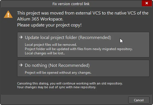
- Note that if a project collaborator does not connected to the team Workspace and then commits VCS design changes, these will continue to be registered with the external repository and therefore out of sync with the migrated Workspace VCS project.
- During migration, Altium Designer executes a commit to the original repository to set a notification mark so it can be recognized as having been migrated by other team members' instances of Altium Designer.
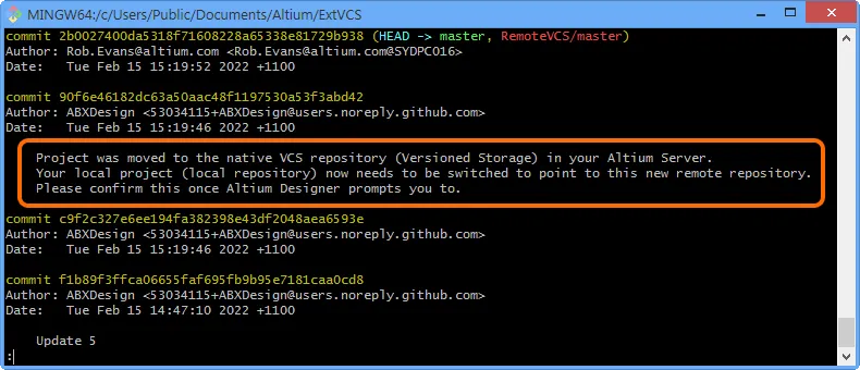
Manually migrating a project from External VCS to Workspace VCS
In some cases it may be desirable to manually migrate a project that uses an external VCS repository to one that is fully managed on an Altium Workspace and its native Git VCS repository. This can be done by creating a snapshot of your project, which disconnects it from external VCS and from the Workspace (if already made available there), and then making it available to the Workspace again, but under the Workspace's VCS – starting afresh as it were. To do so, follow the procedure below:
- Disconnect (remove) your project from the external version control system. This can be performed from your external interface tool to your current VCS, or through Altium Designer. In the case of the latter, while there are commands to remove the project from version control in both the Projects panel and the Storage Manager panel, the cleanest way is to use the Project Packager. Using the Project Packager will create a snapshot of your project, without the baggage of version control and, if you have previously made the project available to the Workspace, it will strip the links to the project in the Workspace.
If you have already made the project available to the Workspace, you'll want to unlink it as part of the packaging process. To do so, in the Managed Projects region on the Zip File Options page of the Project Packager wizard, make sure to enable the option to Unlink project from the server during packaging. This will ensure the link information to the mirrored project in the Workspace – which resides within the project file (*.PrjPcb) – is removed as part of the packaging process.
- Unpack your 'cleaned' project from the Zip archive created by the Project Packager.
- Open the project in Altium Designer – notice that it is neither managed (if it was previously) nor under version control. It is therefore a clean, unmanaged project.
- This next step is only if you had previously made the project available to the Workspace. The packaging process unlinked the project, but the mirrored project in the Workspace still remains untouched. You should delete the server-side project first. Access the Workspace's browser interface (through the Altium 365 Platform Interface). From the Projects page, click to select the project to be deleted, then click the
 control and choose the Delete command from the context menu.
Should you wish to keep the older version of the project in the Workspace, you should either rename it, or rename the fresh instance of the project when making it available online – whichever best suits your requirements.
- Now make the project available online again to the Workspace. To do this, right-click on its entry in the Projects panel and select Make Project Available Online from the context menu, giving access to the Make Available Online dialog. Make sure you enable the Enable Formal Version Control option, as this is what adds the project under the Workspace's own built-in VCS (Git). For more information, refer back to the section Make an Existing UnManaged Project Available Online.
As an alternative to the above step, the unpacked project snapshot (see step 2, above) can be directly uploaded to the Workspace using the
New – Upload Project option available in the
Projects view of the
Workspace browser interface. The resulting created project, available for opening in Altium Designer, is fully managed by the Workspace and its native VCS repository.
Note that the project essentially starts its history afresh – no previous version history is kept. By using the Project Packager, and taking a snapshot of your design at that point rather than removing the project from version control, you will retain the history for the previous VCS-linked project up to that point in time.
Controlling Project Synchronization
Once an unmanaged project has been made available to an Altium 365 Workspace, controls over its online availability and synchronization are provided through the General tab of the Project Options dialog.
Note that the Online Availability and Synchronization options are presented only when Altium Designer is connected to an Altium 365 Workspace, rather than a Workspace provided by an on-site server such as Altium Concord Pro.
 Options and controls relating to having made the project available online are presented on the General tab of the Project Options dialog.
Use the option available in the General region of the tab to make changes to the project description. This affects the mirrored project within the Workspace only.
In the Online Availability and Synchronization region of the tab, the Version Control option reflects the current style of online availability:
- Option Enabled – the project (and its source files) are stored under the Workspace's own native VCS (Git). This is the recommended approach, as by doing so you will have access to the maximum functionality offered through, and by, the Workspace and the Altium 365 platform.
- Option Disabled – the project files are stored in the Workspace for basic access and to enable sharing with others for viewing and commenting only – the Simple Sync arrangement.
Use the option to change between these two as desired.
This option is not available if the project is stored under an external VCS repository.
Should you wish to stop the synchronization between your local project, and the managed incarnation of it that was made available in the Workspace, click the  button. The Turn off project synchronization window will appear. Click on the Unlink option, then click OK back in the Project Options dialog. The local project will no longer be associated with the project in the Workspace.
This is reflected in the Projects panel after saving the local project, by the project being presented under the active Project Group (*.DsnWrk), rather than as an entry under the active Workspace. A save is required since the links to the project in the Workspace are removed from the project file.
The project in the Workspace remains untouched – it is not removed by this action.
 You can sever the connection between your local project and the incarnation of it made available in the Workspace.
You can always make the unmanaged project available online again, as a mirrored or full VCS project (Version Control). The General tab of the Project Options dialog will present the  button, with which to access the Make Available Online dialog. Refer back to the section Make an Existing UnManaged Project Available Online for more information.
If you are making a local project available online again after having turned off synchronization, you may need to change the project name. Since turning off synchronization does not remove the project in the Workspace, this project, with the same name and folder location, may still exist. If you need to have the same project name, then the previous project instance in the Workspace can always be removed.
 A local, unmanaged project can also be made available online – in the Workspace – from the General tab of the Project Options dialog.
Sharing a Project
Related page: Sharing a Design from within Altium Designer
Once a project is managed (available in the Workspace), you'll want to determine which users can actually access that project. This is done by sharing the project, or rather by configuring its access permissions. Note that a newly created project, or one made available in the Workspace, is shared with the following by default:
- The Owner of the project, which is usually the designer who created it (or made it available in the Workspace): with full (Read/Write) access permissions.
- The Administrators role: with full (Read/Write) access permissions.
Controls for sharing a design from within Altium Designer can be found in the Share dialog – accessed in the following ways:
- For the active project – by clicking the
 button at the top-right of the main application window, or by choosing the Project » Share command from the main menus.
- For the focused project in the Projects panel – by right-clicking on the entry for the project and then choosing the Share command from the context menu.
If there is no active project – i.e. no project document currently open – then the

button will act on the currently focused project in the
Projects panel.
 Accessing the Share dialog – command central for sharing a design from within Altium Designer.
The following levels of sharing are supported from within Altium Designer:
- Share Project – share the actual WIP design itself with other members (Users) of your Workspace team, as required. Use the available control to determine access rights (Can View by default). View and comment from within Altium Designer, or in the Workspace interface. Use the
 menu to set the project sharing permissions for the added user(s). Editing can only be performed through Altium Designer.
-
When connected to a Workspace on the Altium 365 Platform, you can also share an active WIP design with those outside your team, such as external contractors, without them gaining access to your full Workspace or design data. The invited person must be registered with AltiumLive, and can access the shared design from their Altium 365 Personal Space (or their organization's Workspace, if available), or open it in their Altium design client for editing.
-
- Snapshot on the Web – a static snapshot of the design at a particular point in time that can be shared with others, perhaps for a design review, or maybe with the manufacturer for a cost estimate. Two levels of sharing are supported:
- By link – available to anyone through a Web browser. Using the Share dialog to share at this level requires neither active subscription for your Altium Designer licensing, nor registration with AltiumLive. A recipient of the shared link uses the Standalone Altium 365 Viewer to view (but not comment) on the design through their browser. Viewing requires no registration with AltiumLive and the link is available for 48 hours.
- With specific people – available to specified people through email invite. Using the Share dialog to share at this level requires registration with AltiumLive, but does not require active subscription for your Altium Designer licensing. A recipient accesses the design snapshot through the Altium 365 Platform Interface Web Viewer from an email invitation. Viewing requires registration with AltiumLive, but the snapshot is available permanently. Commenting of the design is also available.
For more information on:
For information on:
Opening a Project
To work on a managed project, you effectively check it out as a local working copy. This is performed directly from within Altium Designer using the File » Open Project command. What happens next depends on whether you are a member of the Workspace team, or have been shared a project outside of the Workspace team:
- Workspace Team Member – the Open Project dialog will appear, from where you can choose which managed project to open from your connected Workspace (when connected to a Workspace, that Workspace will appear in the Locations region of the dialog, distinguished by the
 icon, and appearing with the name given to the Workspace). Only those managed projects that have been shared with you (you have permission to access) will be listed.
- Once opened, the project will appear under an entry for the Workspace, in the Projects panel.
-
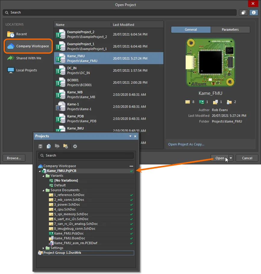
- Choose which managed to open from your connected Workspace, from within Altium Designer, from those currently shared with you.
- You have the option to open the project to the default checkout path, or use the
 drop-down menu to specify a custom path. The default checkout path is defined as a property of the design repository in which the project resides. For a Git repository (e.g. the Versioned Storage repository that is native to the Workspace), this is the Local Path field found in the Git Repository dialog. For an SVN repository, this is the Default Checkout Path field found in the SVN Design Repository dialog. Access the properties dialog by selecting the entry for the repository – on the Data Management – Design Repositories page of the Preferences dialog – and clicking the
  button.
- Choose the Open Project As Copy option to create a cloned version of the project under a different name.
- When browsing the project through Altium Designer's Explorer panel, click the
 button, at the top-right of the panel, to open the project in Altium Designer (adding it to the Projects panel).
- Invited Stakeholder Outside of the Workspace Team – the Open Project dialog will appear, from where you can access any managed project that has been shared with you from the Shared With Me location.
You have the option to open the project to the default checkout path, or use the

drop-down menu to specify a custom path. The default checkout path is taken from the
Document Path field on the
System – Default Locations page of the
Preferences dialog.
Cloning a Project
To clone a managed project from within Altium Designer, right-click on the entry for the project in the Projects panel and choose the Clone command from the context menu. Use the Clone Project dialog to determine the Project Name, Description (which is not pre-populated), the Folder path (within the Workspace), and the Local Storage path (to the working copy).
 Clone a managed project from within Altium Designer.
 Clone a managed project from within Altium NEXUS.
When browsing the project through Altium Designer's
Explorer panel – configured in its default
Project View rather than
Classic View – the project can be cloned by clicking the

button, at the top-right of the panel.
Working with Project Documents
Once a project is established design documents can be added, edited or removed from the active project. These operations can be performed within the Projects panel, which provides an organized view of the project structure and its constituent design documents. The panel's right-click context menus offer the majority of commands required for working with design documents.
► See the Projects panel page for more information.
Note that the presentation of documents in the Projects panel does not reflect how they are stored on the hard drive or elsewhere. The panel's contents can be considered as a logical representation of the project, whereas the physical location and organization of the document file storage (and its type) are up to you – the documents might be stored in a folder on your local machine or a LAN, and of course, hosted in a version-controlled repository provided by a basic Git/SVN VCS system or a fully managed system such an Altium Worskpace.
► See the Storage Manager panel for information on the management of project documents from a traditional file storage perspective.
More on Working With Project Documents
As you work with project documents in Altium Designer, the Projects panel provides a visual summary of which document files are modified, saved or hidden through status icons that are associated with each design document, and the main project file. The basic document icons and their status meaning are listed below:
| [blank] |
Closed – The document is not open. |
 |
Open – The document is open as a tabbed document in the design editor window. |
 |
Hidden – The document is hidden (open, but not displayed in the Workspace). |
 |
Modified – The document is open and has been modified (yet to be saved). |
 |
Modified (project) – This icon appears next to the main project document to show that its structure has been modified (yet to be saved). |
► See the Document Display Icons section in the Projects panel page for more information about document status icons.
A modified document or project that has yet to be saved is also distinguished by an asterisk next to its entry in the panel. Modified documents are also indicated by an asterisk inside their tab in the design editor window.
Add or Remove a Design Document
The simplest way to add new or existing design documents to a project is to right-click on the project name in the Projects panel and select Add New to Project or Add Existing to Project from the context menu options.
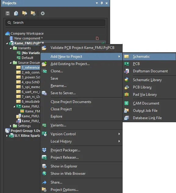
Add a specific or another type of document to a project.
Other types of project-relevant documents can also be added to a project, such as text files, PDFs, spreadsheets, etc. To do so, use the Add Existing to Project option and set the File Type drop-down list in the Choose Document to Add browser dialog to All Files (*.*) so all file types can be accessed.
To remove a document from the project structure, right-click on its name in the Projects panel and select the Remove from Project menu option. Note that this process removes the project's link to that document, and does not delete the source document file itself.
Change Project Document Order
Documents in the Projects panel are automatically arranged in logical groups or 'folders', such as Source documents (Schematic, PCB, etc.), Settings documents (Harness, Outjob, etc.,) and in the case of a hierarchical design, top-level schematic documents. The documents within each folder group are displayed, by default, in the order they were added, but can be dragged and dropped to a new order position within the group.
In the case of a new hierarchical design, the parent-child relationship between documents will be displayed in the Projects panel. Note that the connectivity relationships cannot be defined by dragging and dropping schematic documents since the inter-sheet connections and design hierarchy are in fact defined by Sheet Symbols and Port definitions.
► For more information about project hierarchy, see Creating Connectivity and the Net Identifier Scope section in the Options tab of the Project Options dialog.
Share Documents Between Projects
Because an Altium Designer project defines and saves links to stored document files, any number of projects can be created that link to those same documents files.
While this may be a convenient way to re-use established design documents – say, including a standard power supply schematic in several projects – it is not recommended practice because a change in the document will affect all projects it is linked to. A far better approach for design reuse is to establish and apply Managed Sheets.
► For more information about design document reuse and Managed Sheets, see the Managed Sheets page.
Save a Copy of a Document
An open project document can be saved under a new name using the File » Save As command, which creates a copy of the document file under the nominated new name. This process automatically adds (links) the new document copy to the active project in place of the existing (source) document, which remains intact in the source folder. If the open document is not part of a project – a free document – the new copy is simply opened in the editor in place of the original document.
If the intention is to just make a back-up copy of a document, use the Save Copy As option. This creates a named copy of the document file without affecting its host project.
If the intention is to rename a document, see the following section.
Project and Design File Renaming
You can directly change the name of a PCB project (*.PrjPcb) or any of its constituent design files (*.PcbDoc, *.SchDoc, etc) by using the Rename command – available from the right-click context menu for a project in the Projects panel.
 Examples of renaming a project and one of its design files, locally from within Altium Designer. Those changes will be synchronized with the Workspace when you save and send the changes to that Workspace.
With renaming performed, save the changes to the Workspace using the Save to Server command (available from the same context menu for the project). File rename synchronization is maintained between the local working copy of the project and its counterpart in the Workspace. Additionally, when the project file name has been renamed and the project saved to the server, the Workspace automatically changes the managed project's Name parameter to match.
Conversely, when the name of a managed project is updated through the Workspace's browser interface, the change is propagated to Altium Designer when the project is next opened.
To edit the properties of an existing managed project in the Workspace, select its entry on the
Projects page, click the

control above the listing of projects, and choose the
Edit entry on the associated menu. Change the name for the project in the subsequent
Edit Project window that appears.
When the updated project is opened in Altium Designer (File » Open Project), an initial dialog provides the option to align the local project file name with the new project Name, or force the server project Name to match the existing project file name.
 Options available if you have renamed the project on the Workspace side.
Working Copy to Workspace Project Sync Resolution
The application of fully managed, version-controlled PCB projects relies on the tight synchronization between the project's local working folder contents and the Workspace's versioned storage. If this relationship is disrupted by changes made outside of the normal processes, the managed project structure can become corrupted.
Possible changes that break the local-remote storage synchronization include manual actions such as renaming, moving, or copying/cloning a working project folder. These issues are detected and addressed through a choice dialog that highlights a recommended action based on the situation. In general, its options are to resynchronize the folder project as the current managed project or to remove the project's relationship with the server (make the project unmanaged).
 Options to get you back into sync if you have manually changed the location of your local working copy of a project.
Other more complex synchronization disruptions may be caused by changes in the server identity, such as when the server itself has been renamed or moved, when a local project file has been overwritten with one that contains different server identity parameters, or the project's target repository has changed. Such issues create a disparity between the server and the local project repositories, and are reported by warning dialogs or dialogs that provide a resolution choice.
 Options to get you back on track if the repository targeted by the local working copy of your design project has changed.
Soft Delete
Flexible functionality is available for removing managed design items such as Projects, Components and Released data directly from within Altium Designer, from the Explorer panel. Operating as a 'soft delete', the removal process provides increased options and information as you proceed, including relevant links to source items for review purposes. In the Workspace, deleted items are moved to a dedicated Trash location, where they can be retrieved (Restore) or completely removed (Permanently Delete) from the Trash page of the Workspace's browser interface.
For a Project, only the owner or an administrator can permanently delete or restore from the Trash.
 Soft delete in action. Here, a project is being deleted, along with its related release (if manufacturing packages had been created from any releases, those would also be deleted).
Where a managed item has been soft deleted, this will be flagged in relevant areas of Altium Designer, wherever that item was being used or referenced. For example, for a soft deleted component item, this is indicated during project Validation and also in component access locations such as the Properties panel and the project's ActiveBOM document.
 Example of a soft-deleted component being flagged as such elsewhere in the software.
Project Commenting
Altium Designer projects, when integrated with an Altium Workspace, enable a dispersed design team to collaboratively work on projects that are centrally stored and managed through that Workspace. To enhance the design collaboration process, the design interface supports the commenting of design documents. Comments – user-added notes – can be applied to a point, object, or area on a schematic or PCB document and may be replied to by other users.
Altium Designer also includes logic and visual indicators the help to prevent design editing conflicts that can occur between design collaborators. Based on central communication through the common Workspace, the system graphically shows who else is viewing or editing a currently open design document, and also provides alert messages when there is potential for save/commit file conflicts.
► See Collaborators Visualization & Conflict Prevention for more information.
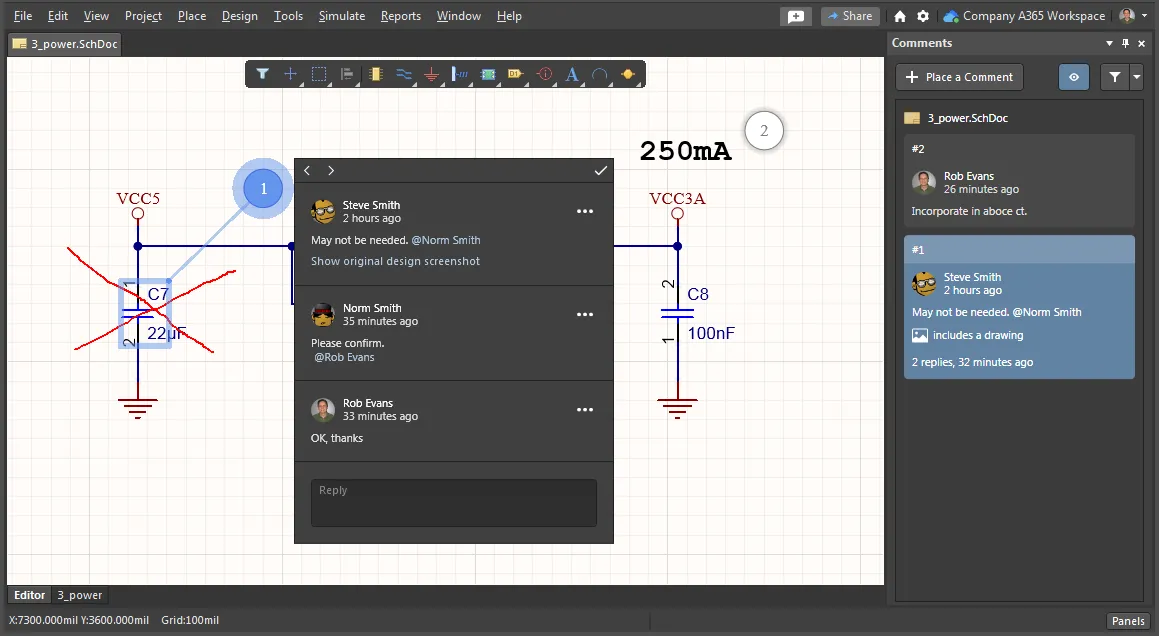
Placed comments are available in real-time to collaborating users – those that have shared access to the document – and are saved to the server independently of the project, without altering its constituent documents in any way. The commenting feature is managed through the Comments panel (View » Panels » Comments), which provides the means to place, select, edit, resolve and remove comments. Within the document editor, the comments are effectively 'pinned' to document locations, and are accessed via an associated pop-up window.
For information on Projects from an Altium 365 Workspace perspective, see
Workspace Projects.
For more information on Projects from an Altium NRXUS Workspace perspective, see
Managed Projects.
Note that Comments can be added and managed in both Altium Designer and in the related Workspace, via its web interface design view. The functionality of the two commenting systems is essentially the same, and since both the project and commenting data are stored in the Workspace, the systems work together in real time.
Prerequisites
Before using the commenting feature, ensure that you are signed in to your Workspace, and have opened a Project and one of its schematic or PCB documents. Use the File » Open Project command to choose a Workspace project from those that have been shared with you. The Comments panel will provide textual hints for these prerequisites:
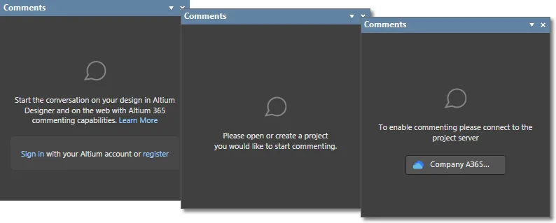
Placement
Comments are placed in the editor space from the  command button available in the Comments panel or by clicking
  near the top right of the design space and may be assigned to an object, a specific point, or an area on the active document. The command invokes the comment placement mode, where the cursor changes to a crosshair that detects and highlights objects for selection:
- Click a highlighted object to attach (pin) a comment to that object.
- Click in an un-highlighted area to attach a comment to that specific point on the document.
- Click away from an object and drag the cursor to create a rectangular highlighted area, and then click again to confirm its final shape to attach a comment to the specified area. ► See example
 .
.
The placement action then opens a comment entry dialog that offers a field for entering the comment text, and also additional options for adding a freehand drawing to the comment ( ) and including a 'mention' reference to a specific user or group (
 ). Click
  to confirm the comment creation, which will associate the comment with a numbered pin marker on the document and also add a comment summary entry to the Comments panel.
Placing a comment on an object, mentioning another registered user in the comment, moving the comment's pin indicator, and adding a freehand drawing to the comment.
A placed comment is immediately available to all users that have access to the project, and also will be available in the browser-based project view of the connected Workspace.
Mentions and Assignments
Along with text in the comment entry dialog, a 'mention' reference can be added for any other user or role registered with the connected Workspace by entering the @ character or clicking the dialog's  button. Select a name/email from the dropdown list to add the user (team member) reference to the comment, and also as an Assign To entry. Uncheck the latter option if you do not wish the comment to be regarded as specifically assigned to that user or group. A Role group (say, 'Engineers'), and therefore its constituent users, may also be added as a mention and/or assignment.

If a mentioned user does not have access to the current project you will be invited to share it with that user – this option is available if you are the project owner or a Workspace administrator. User Access Rights are granted through the Share dialog, and the user will receive an email notifying them of the shared access. The project will not be shared if you cancel the Share dialog, but the comment will be placed as usual.
► See more information about sharing a design.
Positioning
A comment's location in the editor space is moved by dragging its associated 'pin' to a new position – during or after its placement. When selected, the comment pin includes a connecting line to its associated object or area.
While you can move (drag) a comment pin around in the document editor, the initial defined point or area cannot be modified.
Note that a comment also may be positioned during its initial placement by clicking and dragging when in placement mode. ► See example .
.
Drawing
When placing or editing a comment, select the  option to add freehand drawing with the resulting pen cursor. Click and drag to create lines, and then right-click to finish and associate the drawing with the currently selected comment.
Press Tab during placement to open the Freehand Drawing mode of the Properties panel in which you can configure the width and color of the freehand drawing.
PCB Comments
Comments also can be placed on a board layout in the PCB editor space using the same placement approach to that in the schematic editor. When a comment entry is selected in the Comments panel, the system will open (and load if necessary) the associated design document. ► See example .
.
Working with Comments
Comments placed in a design document are registered in both the Comments panel (as a sequence of numbered entries) and in the corresponding document editor (as numbered pin graphics). Each panel entry represents a comment thread and provides summary information that includes who placed the comment and when, the initial comment text, any applied mentions/assignments, and the number of thread replies.
A comment thread is opened by selecting its entry in the Comments panel, or by clicking on its associated pin in the editor space. This highlights the comment in the document editor and opens the comment entry dialog, which includes the initiating comment and any user replies. If a selected comment is associated with another design document, the system will open (and load if necessary) that document.
Navigating comments by selecting pin markers in the editor space, and by selecting entries in the Comments panel.
Comments Dialog
Interaction with a placed comment is through the pop-up comment dialog, which shows all entries in the selected comment thread and includes options to preview, reply, edit, resolve and delete an entry. The dialog is opened when initially placing a comment, or when a placed comment is selected in the Comments panel or in the document editor. Press Esc or click in the editor space to close the comment dialog.
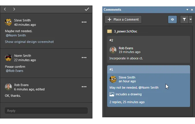
You can sequentially step through all available comments using the previous/next buttons (

) in the dialog's header.
Preview
Select the Show original design screenshot option in the initial comment to see a graphical capture of the editor area when the comment was placed.
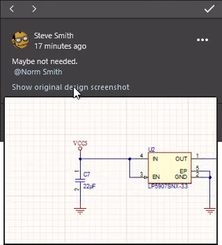
Reply
Enter text and optionally a user mention (@), in the reply field to add a new entry to the comment thread. Click  to confirm the entry.
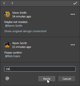
Edit and Delete
An existing comment may be edited by the author of that comment using the Edit option available from the comment's  menu. Click the
  button to confirm the comment edit.
Use the Delete option to remove the currently selected comment. Note that the entire thread will be removed if the initial comment (as opposed to a Reply) is deleted.
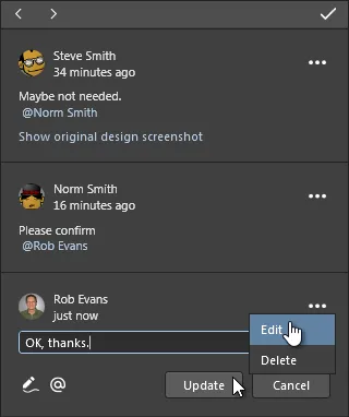
Resolve
Click the dialog's  button to toggle the comment state between Resolved and Unresolved (the default). A resolved comment (closed as complete) is inactive and non-editable, and both its entry in the Comments panel and its pin marker on the document are grayed out.

Comments panel options
Use the buttons at the top of the Comments panel to set the availability of comments in the panel and editor space, and to specify if mentioned users are notified.
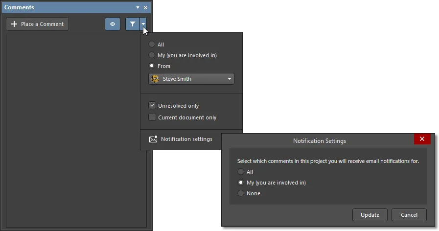
The panel's  button toggles the visibility of comment marker pins on the document. Comment entries still may be selected as usual in the Comments panel listing.
Use the options drop-down menu ( ) to configure comment visibility filtering and notifications, and the associated
  button to toggle between the filtered and unfiltered view:
- All – all comments placed on the design will be listed in the panel.
- My – show only those comments that mention my user name and/or are assigned to my user name.
- From – show comments placed by the selected user only.
- Unresolved – comments that have been resolved are not included in the panel (or document editor).
- Current Document – list only comments that have been placed on the currently active document, as opposed to all project documents.
- Notifications – receive email alerts for all comment activity in this design (All), for only those comments where you are mentioned or assigned to (My), or do not receive email alerts at all (None). ► Email content example
 .
.
Releasing a Project
In conjunction with an Altium Workspace, Altium Designer provides an advanced approach to organizing, tracking and storing the design output files required for manufacturing a PCB design project. This employs an automated process that ‘releases’ a specific set of design output files to the server as read-only revisions, which collectively corresponds to a physical entity that may be manufactured. The revisions created by this Project Release process are stored in the Workspace's VCS repository, are lifecycle managed, and represent a manufacturable snapshot of the PCB design at the time the release was created.
The Project Releases that follow, as the design progresses, are automatically committed as new release revisions, allowing a sequence of releases to be created as the design changes and evolves. Previous revisions are read-only and may be viewed or downloaded from the Workspace at any time.
A board design that is released or 'committed' to the Workspace (as a set of lifecycle-managed Revisions) generally includes:
- Source Data – a time-stamped copy (snapshot) of the core project design files (schematic, PCB and Project file, etc.).
- Fabrication Data – the data required by a Fabrication House to create the bare board (Gerber files, NC Drill files, etc.)
- Assembly Data – the data required by an Assembly House to fully populate the bare board according to a Bill of Materials, both with and without any design Variations (Pick and Place files, Assembly Drawings, BOMs, etc.).
The Project Release can also be used in an
offline mode, where the generated release files are created in a specified folder or ZIP archive file on the local machine. If the current project is saved to a Workspace or you are not signed in to a Workspace, the Project Releaser will automatically offer the offline release mode. Read about the
Project Releaser's Offline mode.
The prerequisites for releasing a PCB design to a Workspace are:
- Altium Designer is signed in to the Workspace, which hosts the target repository for the release.
- The Altium Designer PCB project includes suitable Output Jobs – design data output generators (for outputs such as print, file or PDF). If no OutJobs are available, the Project Releaser will offer to create suitable Fabrication and Assembly Outjobs to drive the process.
- The project sourced by the Release process has all required elements in place – the source data is valid and up to date, the user has sufficient rights to release that project to the server, etc.
The essentials of these requirements are outlined below.
Output Jobs and Files
The fundamental method of generating design output from Altium Designer is through a range of available design Output Generators that produced the data files and artwork needed to create the real-world version of the design – in other words, the Schematic and PCB Prints, Gerber and NC Drill fabrication files, Bill of Materials (BOM), Pick and Place Assembly files, etc., that are required to fabricate and assemble the PCB design.
The selected Output Generators and the specific Output files they will create for a design are collectively defined using the Output Job Editor, which saves the generator to output mapping configurations in an Output Job file (*.OutJob) – created via the File » New » Output Job File command.
Within the editor, the available Output types are arranged in functional sections (Documentation Outputs, Fabrication Outputs, etc.,) and are enabled by selecting a sub-type and the design document source. The selected Output is then linked to a target Output Container (such as a PDF, file, or a printer) – as shown below.
 The Output Job Editor allows a wide range of design output generators to be targeted at output containers (files, printers, location paths, etc.,), and the configuration saved as an OutJob project file.
As the core mechanism for collectively generating manufacturing and assembly files for a board design, Altium Designer Output Jobs offer the following additional capabilities:
- Any number of OutJobs can be added to a given design, so that configurations will be available for specific tasks such as generating outputs for fabrication, assembly, archiving, procurement and documentation.
- OutJob files are in fact portable and can be applied to any design project where a standardized set of design outputs are required. Choose 'PCB Document' as the document source option, rather than a specific design file, to create a generic (and therefore portable) Output Job.
- OutJobs can include files for design Validation checks, such as electrical (ERC), Rule (DRC) and Footprint to source comparisons. As such, Validation output jobs are a specialized 'active' case where the design is checked and the actual output (such as a PDF document) represents the results of the validation process.
- OutJobs cater for variations in an assembled board design, where different sets of output files are required to manufacture alternative versions of the design – such as standard or uprated versions of the product that uses additional components or different types. See Design Variants for more information on board design variations.
Note that a
Variant Choice nominated by an Output Job does not apply when the OutJob is used in the
Project Release process. In that case, Variant choices are automatically detected and/or specifically nominated in the Releaser itself.
► See Preparing Multiple Outputs in an OutputJob for more information on Output Jobs.
When releasing a design to a Workspace through the Project Release process (see below), the available OutJobs (such as those for Assembly and Fabrication) can be nominated for use by the Releaser. Additional Output Jobs that are included in the design project may also be added to the release setup through its Options dialog. The Release process uses the selected OutJobs to map specific sets of files and project production data to target Items (data containers) in the server's repository.
The Project Releaser
With a PCB project’s required Output Jobs created, the design is ready to be released by the Project Releaser as a manufacturable set of design data release packages in the Altium Workspace. Using a sequence of checks and file generation processes creates a specific collection of board design data that represents a particular physical item (such as a fully assembled PCB) or set of physical items.
► See Working with the Project Releaser for more detailed information.
To access and set up the Project Releaser, open its Release view from the Altium Designer main menu (Project » Project Releaser) or right-click on the project name in the Projects panel and select Project Releaser.
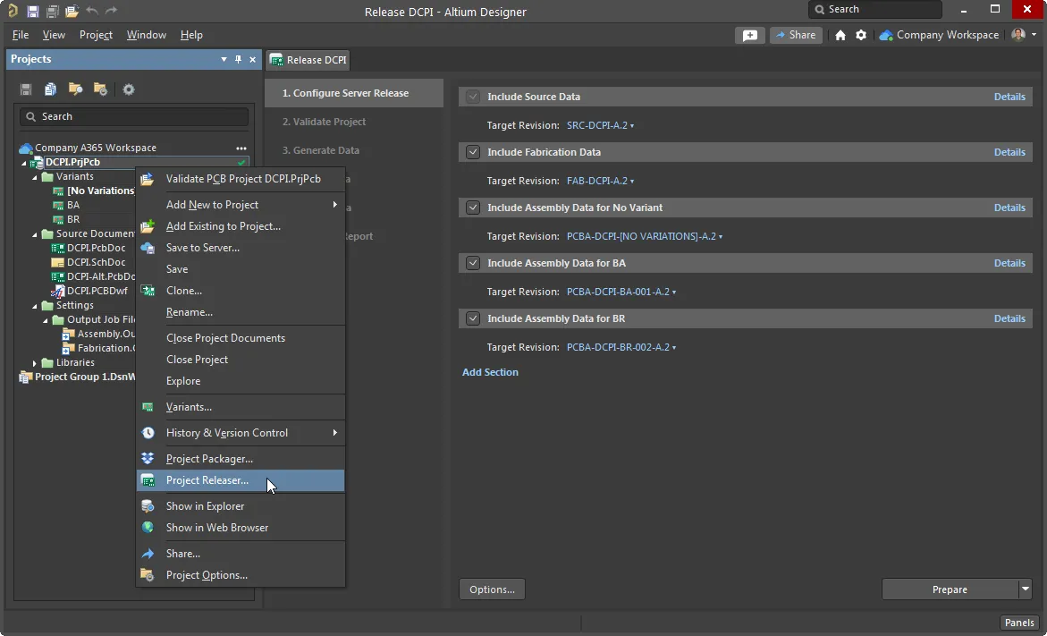
The Project Releaser is an automated process that works through a sequence of checks and output file generation stages targeted at an Altium server or a local folder/zip.
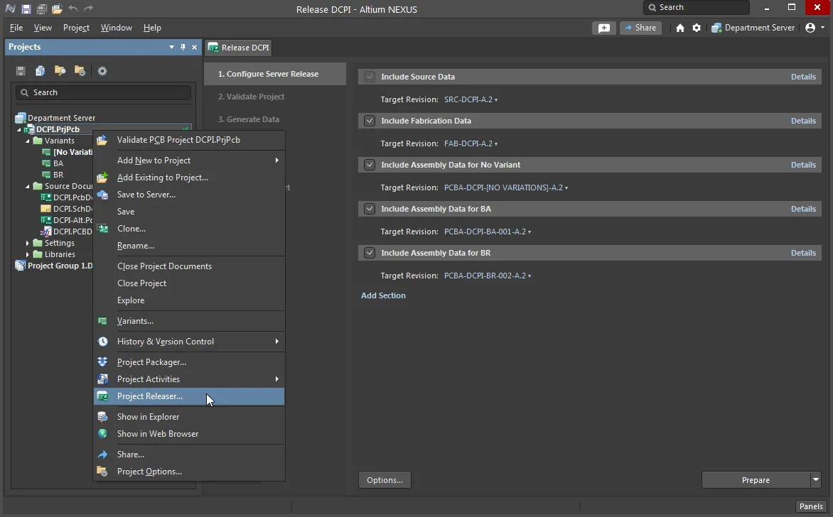
The Project Releaser is an automated process that works through a sequence of checks and output file generation stages targeted at an Altium server or a local folder/zip.
If the Workspace targeted for the release has an activated Project Releaser with Publish process, then this will appear as an additional, final stage in the Project Releaser – typically named Publish to PLM.
This step will push the released project data to the registered PLM instance, which then generates PLM part numbers for each created PLM item and sends the data back to the NEXUS as accessible PlmPartNumber parameters.
► See Working with the Project Releaser for more information on its Publish to PLM stage.
► See Publishing to a PLM for information on using PLM processes in the design environment.
► See PLM Integration for information on configuring a PLM instance in the NEXUS server.
The Project Releaser's Release View offers an initial setup page that corresponds to the first stage of the release process sequence – Configure Server Release. This includes a range of release data sections that represent the type of outputs that will be generated and released to the server, such as the Source data (a snapshot of the project files), Fabrication data and Assembly data.
The automated Releaser will:
- attempt to apply suitable OutJob collections to the data assembly groups, based on the name prefix (
ass, fab) of the available project OutJobs.
- create suitable default Assembly and Fabrication OutJobs if there are no existing OutJobs in the project.
- detect any Variants that have been defined in the active project and create suitable Assembly data sets for generating output files that relate to those variations.
- detect the correct release mode – offline or online – based on the current conditions (Workspace connection status, Managed or Local project type). In this instance, the Project data will be released using online mode.
Additional 'custom' sections can be added (Add Section) to create a separate, nominated collection of output data. The initial configuration for the core data sections (or any added custom sections) can be edited, added to or reconfigured through the Project Release Options dialog, opened from the  button.
 The output jobs defined by a nominated OutJob document will be run (eg: Assembly), and their data collected in that target section (eg: Assembly Data).
The main Release Options include:
- Release Target – select, or browse to and select, either an online Altium Workspace or local folder (offline mode) target for the release.
- Output Jobs – within each listed section (Source Data, Fabrication Data, etc.,), select which of the available OutJobs (and their constituent output generators) will be used in the release. Note that the release Sections are simply predefined data division names that can include the data generated by any selected OutJob.
- Item Naming tab – set the name of the Items that will be created in the server, or browse to and choose (or create) an existing server Item that will be targeted by the release.
- Settings – view or edit the base naming templates for the data Revisions that will be released to the server.
► See the Project Release Options dialog for more information.
A number of
Project Release preference options (such as the temporary file storage location) are available in the
Data Management – Servers page of the Altium Designer
Preferences.
Prepare the Release
When the project release has been set up as needed, invoke the Releaser's preparation process with the  button. This will trigger a series of pre-release checks such as whether the project files have been saved (and committed to VCS), and ensuring that the target locations will be accessible. During this part of the process, the Releaser will also create the release target Revisions in the Altium Workspace. The following processing stage will Validate the project (ERC, DRC, etc.) if a Validation report is included in the project OutJobs.
The final step of the preparation process will generate the data for all outputs defined by the nominated project OutJobs – this targets a local temporary location prior to uploading that data to the Workspace.
 All data and files generated for the release can be reviewed prior to being released to the Altium server.
At this stage, the generated data can be reviewed in the Release view. For the data collection of interest, select the Details link option to expand a full report of the files generated for that section, and use the Explore link to open the (temporary) folder that contains the generated files. Alternatively, use the View link to open the listed entry in its native editor/viewer.
Release to the Connected Workspace
Assuming all is well with the prepared release, the generated data can be uploaded to the Workspace release target that was initialized as part of the previous step. Use the  button to trigger that process, and confirm the action in the Confirm Release dialog.
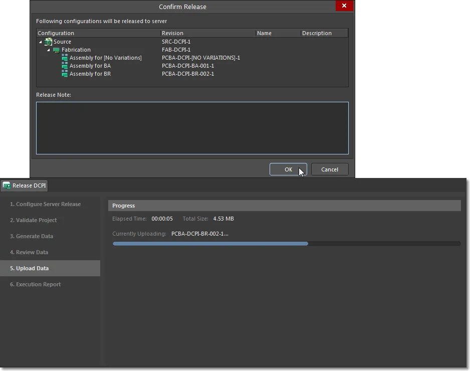
The completed release process will be followed by an Execution Report, which provides a release summary tree and navigation links (top) to the data collection revisions in the Workspace.
 Select a generation section link to open that released revision in the server.
An additional Publish to PLM stage may be available if its corresponding process has been activated in the NEXUS Server Workspace. See Project Releaser – Publishing to PLM for more information.
View a Released Project
Project Release entries are listed in the Altium Designer Explorer panel view of the project (View » Panels » Explorer), with subsequent project releases creating a new set of release revisions (where the revision numbering is incremented). Further access to project Release information is available in the targeted Workspace's Web Viewer, opened via the Explorer panel's  button.
 In the Explorer panel use the Open in Web button to access the releases in the connected Workspace.
Within a Workspace's Web Viewer, all releases associated with the project can be accessed in the Releases view – or in the Manufacture view for Workspace provided by an on-site server such as Altium Concord Pro. The page lists all project releases, with the newest entry at the top, where an individual release can be opened in the Workspace's Manufacturing Portal from its open button ( ).
).
The Manufacturing Portal view provides more detailed information on the selected Release, which includes its constituent release package files (under Files), the full set of design documents (under Design Snapshot), and component Manufacturer and Supplier details (under Supply). Note that the Send to Manufacturer feature is available in an Altium 365 Workspace only. ► See the Altium 365 Workspace Releases View page for more information.
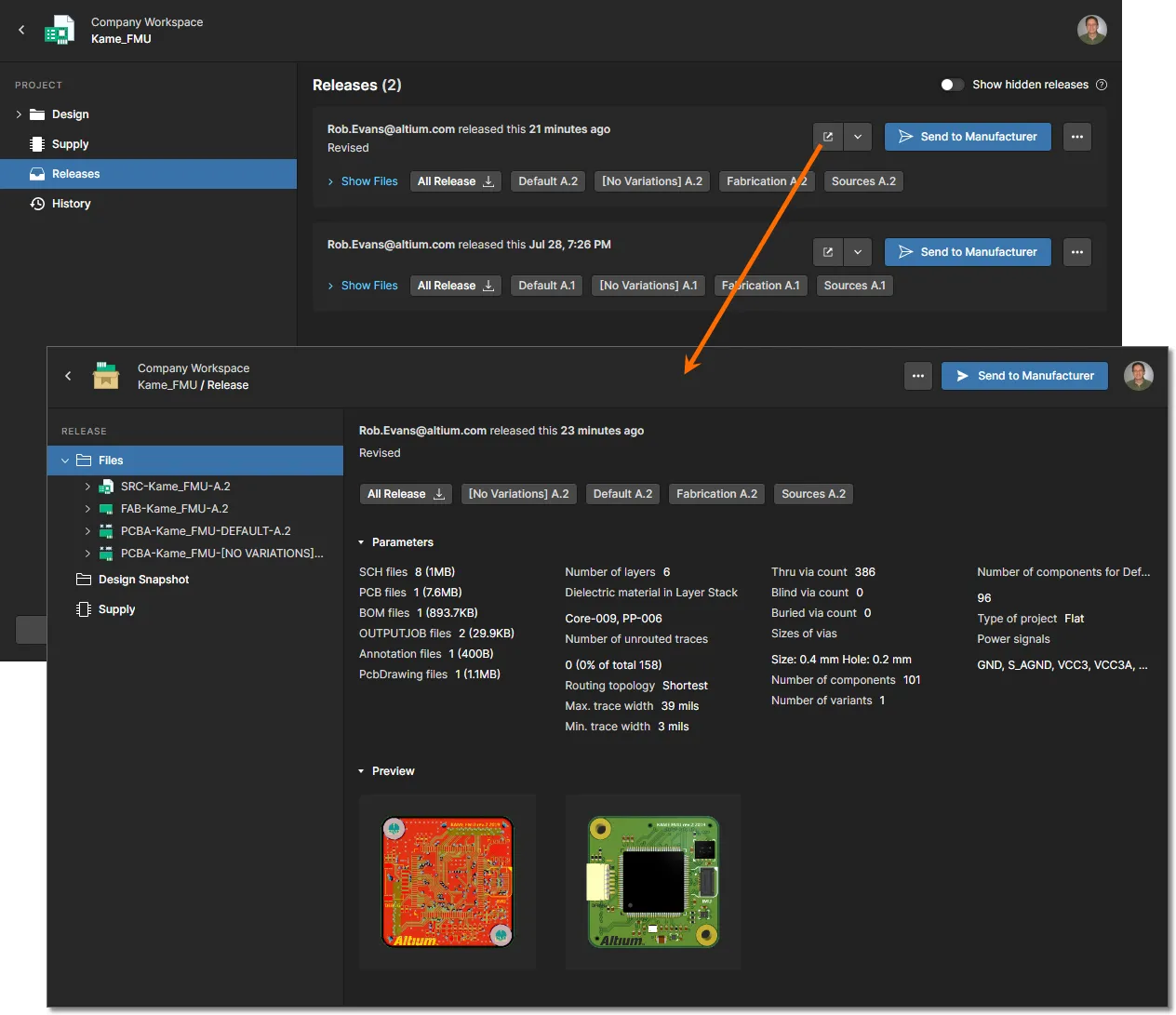
The above Project View and information is also available through the Workspace browser interface – select a project entry under the Projects tab. For more information on accessing and managing project data released to a managed content server see:
► Browsing Server Content
► Browser-based Lifecycle Management
Project History
Altium Designer, in conjunction with a connected Altium Workspace, allows you to view and interact with an advanced graphically orientated Project History timeline. The dedicated History view provides a progressive timeline of major events relating to the project – its creation, commits, releases, clones and MCAD exchanges – with various actions supported where applicable.
To get the most out of this feature requires your project to be fully managed, by ensuring the project is under the Workspace's own built-in VCS (Git).
If your project is under external version control, you can convert it to a fully managed project hosted in the Altium 365 platform by migrating the project to the Workspace's native VCS. For detailed information on how to do this, see Moving from External VCS to Workspace Native VCS.
For information on working with the
History view for a project through the Workspace's browser interface, see
Project History.
Enabling Project History
The Project History functionality is delivered through a purpose-made extension – the Project History extension.
 The Project History extension.
This feature is only made available, provided the
Project History extension is installed as part of your Altium Designer installation. This extension is installed by default when installing the software, but in case of inadvertent uninstall can be found back on the
Purchased tab of the
Extensions & Updates page (click on the current user control (e.g.

) at the top-right of the main application window, then choose
Extensions and Updates from the associated menu).
Accessing the Project History
To access the History view for a project from within Altium Designer, right-click on its entry in the Projects panel and choose the History & Version Contol » Show Project History command from the context menu. The History view presents as a distinct tabbed document (<ProjectName>.PrjPcb History).
 Access the history for a project from within Altium Designer.
 Access the history for a project from within Altium Designer.
For a project in your Workspace that already existed prior to the arrival of the Project History feature, its history will initially not be complete. Reindexing of the event data for that project will be performed automatically when the
History view is first accessed for that project. Notification will appear at the bottom of the view once the reindexing has completed – click the

control to update the timeline with the full historical event data.
History Timeline – Overview
The History view presents a timeline of basic events that have occurred during the project's evolution. It can essentially be broken down into three key sections, as shown in the following image and detailed thereafter.
 Identifying the three key components of the History view.
- Main trunk of the timeline. Direction of event chronology is from the bottom up. The first event – the creation of the project – will appear at the bottom of the timeline. Subsequent events appear above, with the latest (the most current event) appearing at the top of the timeline.
- Events. Each time a supported event (see below) happens in association with the project, that event is added to the timeline as a dedicated tile. Each type of event will have a different colored tile and will either be linked directly to the main trunk of the timeline, or have some additional icon next to it (as is the case for MCAD Exchange events).
- Search. Click the
 control at the top-right of the view to access a search field that facilitates basic searching of the project history. As you type your search string, filtering will be applied to the timeline to present only the events relevant to that search. For more information, see Filtered Searching.
Supported Events
The timeline shows a progression of events that happen during the life of a project. Each of these events appears along the timeline as a dedicated 'event tile'. The following expandable sections take a look at the range of events currently supported and presentable as part of a project's historical timeline.
Project Creation
Refer to: Creating a Project, Making an Existing Project Available Online, Cloning a Project
When a project is created, the Project Created event tile will be added to the timeline. This event marks the beginning of the historical timeline for the project. As such, it can always be found as the entry at the bottom of the timeline. The tile for this event can appear in two distinct variations:
- When the project is newly created within the Workspace. The creator of the project is presented by name (and picture), along with the date and time of the project's creation. The description for the project is also displayed within the tile, if one was entered at the time of creation.
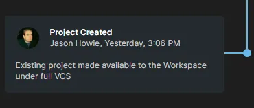
- When the project is a clone of an existing project. The person who created the cloned project is presented by name (and picture), along with the date and time of the project's creation. The description for the project is also displayed within the tile, if one was entered at the time of cloning. A link is provided to the original project – clicking this will access the detailed management page for that project through the Workspace's browser interface.
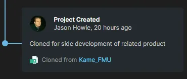
The
Project Created event tile is physically connected to the main trunk of the timeline with a solid blue connection line and node:

.
Project Commit
This type of event is only supported for a project that is fully managed and stored under the Workspace's native VCS (within its
Versioned Storage Git repository). For an unmanaged project that has been made available to the Altium 365 Workspace but is not under formal version control – thereby using the Simple Sync methodology – you will not see any VCS-related commit events on the history timeline. To get this information, you can switch the style of online availability by enabling the
Version Control option, on the
General tab of the
Project Options dialog. This brings the project under the Workspace's native VCS.
For a project that has been made available to an Altium 365 Workspace but is already under external version control, you will also not see any VCS-related commit events on the history timeline. Use your external version control client to examine the project's version control history. Alternatively, you can effectively switch to Workspace's native VCS. What you can do is create a snapshot of your project – performed most efficiently and cleanly using Altium Designer's
Project Packager. This disconnects it from external VCS and from the Workspace (if already made available there), after which you can then make it available to the Workspace again, but under the Workspace's VCS – starting afresh as it were. For detailed information on how to do this, see
Moving from External VCS to Workspace Native VCS.
Each time you Commit a project to the Workspace (where the project is managed under the Workspace's internal Versioned Storage Git repository), a Project Committed event tile will be added to the timeline. The person who performed the commit (Save to Server) is presented by name (and picture), along with the date and time. If a comment was added at the time of the commit and push – through the Commit to Version Control dialog – then that will also be displayed within the tile.
If the project was a local, unmanaged project that was subsequently made available online, then the description that was entered in the
Make Available Online dialog will be used in both the
Project Created event tile and the initial
Project Committed event tile, since the project commit is performed as part of making the project available online – provided of course that the
Version Control option was enabled.
 Example initial Project Committed event tile.
The tile also supports and presents design diffing information, showing more detailed information on what has changed between the current and previous commits. Elements supported include files, components, nets, variants, and PCB structure. The diffing section of the tile summarizes the various elements affected by the commit event, grouped by the following states:
 – element added.
 – element removed.
 – element modified.
Clicking on the  control in the tile will expand this diffing section to present the affected elements by name.
Use the available
Show More and
Show Less controls to interrogate the full listing for each element type. Click on the

control in the tile to return to the summary display.
Click the  control at the tile's top-right corner to access a menu with the following commands:
- Open Snapshot – use this command to download and then open that specific revision of the project (in the Projects panel). The project name will include the date and time at which that revision of the project was committed. Note that this revision is Read-only; you can view, but not edit it in any way.
 You can open (for viewing only) any specific revision of the project – directly from the corresponding Project Committed event tile for that revision.
- Schematic to – allows you to compare the Schematic data in this commit against that of another commit or release event. Use the sub-menu to compare against the previous commit, or select from all possible releases and commits. Once the comparison release/commit has been chosen, the results of the schamtic comparison are presented in the Compare view, which opens as a new tab in your default web browser. For more information, see Schematic Comparison.
- Revert to – use this command to revert to using the data from that specific revision of the project. The data from the project source documents in that specific revision overwrites the data in your local working copy of the project. Effectively, the project is momentarily closed and then reopened with that reverted data. Should you then wish to complete the reversion, and make that data the Head Revision (current version), you will need to commit and push the project back to the Workspace.
 You can revert to any specific revision of the project – directly from the corresponding Project Committed event tile for that revision.
After reverting to a specific revision, and before committing, you can get your local working copy back to the latest revision again by using the Revert to command associated with the latest Project Committed event tile on the timeline.
A
Project Committed event tile is physically connected to the main trunk of the timeline with a solid blue connection line and node:

. The latest revision of the project (i.e. the last commit) is distinguished by having a white fill for its node:

.
Project Release
Related page: Working with the Project Releaser
Each time you perform a release of the project – using Altium Designer's Project Releaser – a Project Released event tile will be added to the timeline. The person who performed the release is presented by name (and picture), along with the date and time. If a release note was added at the time of releasing the generated data to the Workspace – through the Confirm Release dialog – then that will also be displayed within the tile. Each of the data sets included in the release will also be listed.
 Example Project Released event tile.
Click the  control at the tile's top-right corner to access a menu with the following commands:
- Open Snapshot – use this command to download and then open (in the Projects panel) the specific revision of the project from which this release package was generated. The project name will include the release version. Note that this revision is Read-only; you can view, but not edit it in any way.
- Schematic to – allows you to compare the Schematic data in this release against that of another release or commit event. You also can compare schematics between a commit and a release or another commit. Use the sub-menu to compare against the previous release's source data, or select from all possible releases and commits. Once the comparison release/commit has been chosen, the results of the comparison are presented in the Compare view, which opens as a new tab in your default web browser. For more information, see Schematic Comparison.
- Gerber to – allows you to compare the generated Gerber data for this release against that of another release. Use the associated sub-menu to compare against the previous release's fabrication data, or select from all possible releases (the timeline will be filtered to just show Project Released event tiles). Once the comparison release has been chosen, the results of the comparison are presented in the Compare view, which opens as a new tab in your default web browser. For more information, see Gerber Comparison.
As a release of a project is a very significant event, the Project Released event tile is made more prominent – rather than just a 'connected' event, it straddles the timeline as a 'major' event.
Project Cloning
Refer to: Cloning a Project
Each time you clone the project – either through the Workspace's browser interface, or from within Altium Designer – a Project Cloned event tile will be added to the timeline. The person who performed the clone is presented by name (and picture), along with the date and time. If a description was added at the time of cloning – through the Clone Project window (browser-based) or Clone Project dialog (Altium Designer) – then that will also be displayed within the tile. A link is provided to the cloned project – clicking this will access the detailed management page for that project through the Workspace's browser interface.
 Example Project Cloned event tile.
The main
Clone commands available from within Altium Designer (right-click on the entry for the project in the
Projects panel, or click the

button, at the top-right of the
Explorer panel when browsing the project), or from the
Projects page of the Workspace's browser interface, act on the latest (or Head) revision of the project. When accessing the
History view for the project through the Workspace's browser interface, you also have the ability to clone a specific revision of that project. To do so, locate the
Project Committed event tile for the required revision of the project, then click the

control at the tile's top-right corner. From the subsequent menu, choose the
Clone command.
The
Project Cloned event tile is physically connected to the main trunk of the timeline with a dotted green connection line and unfilled node:

.
MCAD Exchanges
Related page: More about ECAD-MCAD CoDesign
When working between the electronic and mechanical design domains, the Workspace acts as the bridge between the two – facilitating direct ECAD-MCAD codesign. Whenever changes are made to the project's PCB design and those changes are pushed to the Workspace through the relevant CoDesigner panel, an MCAD Changes Suggested event tile will be added to the timeline. The person who performed the push is presented by name (and picture), along with the date and time. If a message was posted at the time of pushing – through the MCAD CoDesigner panel (Altium Designer), or Altium CoDesigner panel (in the supported MCAD software) – then that will also be displayed within the tile.
Only Push events are currently supported.
 Example MCAD Changes Suggested event tile.
When the MCAD engineer makes changes to the PCB in their supported MCAD software and pushes them back to the Workspace, the corresponding push event will be available on the project's history timeline only after pulling the changes from the Workspace into Altium Designer.
 Example showing two MCAD-related events. On the left of the timeline's trunk, the push event from the ECAD side, while on the right, the push event from the MCAD side.
The
MCAD Changes Suggested event tile is not physically connected to the main trunk of the timeline. Instead, a directional arrow symbol is used, which points towards the trunk:

.
Filtered Search
Click the  control at the top-right of the view to access a search field with which to quickly find events of interest along the timeline. The search facility supports basic searching of the project history, with dynamic filtering applied as you type your search string – leaving only the events relevant to that search displayed on the page. The matching text within an event tile is highlighted.
The search facility is not case-sensitive.
 Example search of a project's history. The timeline is dynamically filtered as you type your (case insensitive) search term, with matching entries highlighted within each relevant event tile.
A box is provided above the filtered selection that summarizes how many events are currently being shown, along with controls to quickly remove the filter/search string.
The search facility works with the following information:
- Event tile title.
- Person's name who performed the event.
- Descriptive text (the text sourced from a comment/note/description when the relevant event occurred).
- Diffing data text – in a Project Committed event tile.
- Data set name – in a Project Released event tile.
- Project name – in a Project Cloned event tile and Project Created event tile (when created through cloning).
To clear the current filtering and return to the full timeline, clear the search field – either by selecting the current text and pressing the
Backspace key, or by clicking the

control at the far right of the field. Alternatively, click on either the
Clear Filter control in the box summarizing how many events are being shown (at the top of the view).
Updating with New Events
Whenever a supported event happens in relation to the project, that event will be detected and made available to the History view automatically. Notification will appear at the bottom of the view shortly after the event takes place – click the  control to update the timeline with the new event.
A manual refresh is also provided, performed by clicking the

control at the top-right of the view.
The Project Packager
The Project Packager is provided for situations where an entire project needs to be backed up or transferred to another location.
The wizard-based packager archives a complete Altium Designer project, tree of projects or Design Grup(and its constituent projects) to a nominated location as a single time-stamped zip file. The wizard is accessed from the main menu (Project » Project Packager) or by right-clicking on a project name and then selecting Project Packager from the context menu.
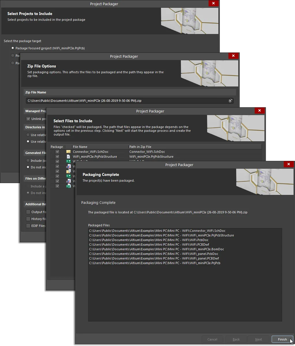
Use the Project Packager to transfer an entire project (or tree of projects) and its linked documents to a timestamped zip file.
The wizard provides options for determining:
- Where the archive is to be stored.
- How file directory paths are handled.
- Whether any generated, system or external files are included.
- If the project history is included.
- Which of a project's linked documents are included in the final archive.
- and more...