The area that the component occupies on the fabricated board is defined by the component footprint. A typical footprint includes pads and a component overlay, and can also include any other mechanical details required. In the example footprint below, most of the component outline is defined on a mechanical layer (the green lines) rather than the (yellow) overlay, because this component will be mounted so that it hangs over a cutout in the board.

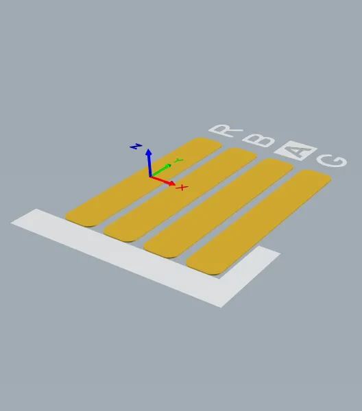
The footprint defines the space the component occupies and provides the points of connection from the component pins/pads to the routing on the board.
The component that is mounted on that footprint can be modeled using 3D Body objects. The 3D Body object is used as a container into which a generic MCAD format model can be imported, as shown in the image below.

A suitable MCAD model can be imported into a 3D Body object.
Even with a rich set of resources providing ready-made PCB components (such as the Manufacturer Part Search panel), it is likely that at some point in your career you will need to create a custom PCB component. PCB component footprints are created in the PCB footprint editor using the same set of primitive objects available in the PCB editor. In addition to footprints, company logos, fabrication definitions, and other objects required during board design can also be saved as PCB components.
Creating a New PCB Footprint
Copy Link
Copied
Footprints can be created directly in your connected Workspace.
-
Select File » New » Library from the main menus, then in the New Library dialog that opens, select Create Library Content » Footprint from the Workspace region of the dialog.

Create a new Workspace Footprint using the New Library dialog
-
In the Create New Item dialog that opens, enter the required information, make sure that the Open for editing after creation option is enabled and click OK. The Workspace Footprint will be created and the temporary PCB footprint editor will open, presenting a .PcbLib document as the active document. This document will be named according to the Item-Revision, in the format: <Item><Revision>.PcbLib (e.g., PCC-001-0001-1.PcbLib). Use the document to define the footprint as described below.
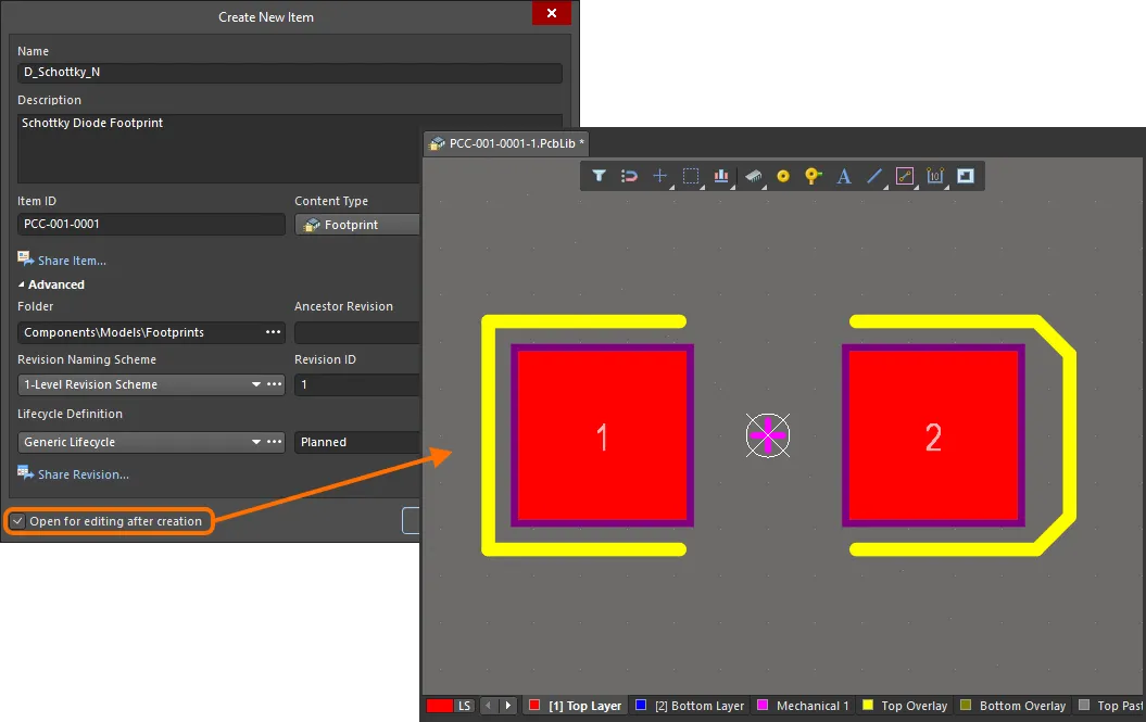
Example of editing the initial revision of a Workspace Footprint – the temporary PCB footprint editor provides the document with which to define your footprint.
- When the footprint is defined as required, save it to the Workspace using the Save to Server control to the right of the footprint's entry within the Projects panel. The Edit Revision dialog will appear, in which you can change Name, Description, and add release notes as required. The document and editor will close after saving.
A saved Workspace Footprint can be used when defining a component using the Component Editor in its Single Component Editing mode or Batch Component Editing mode.
Workspace Footprints can be browsed using the Components panel. Enable visibility of models by clicking the  button at the top of the panel and selecting Models, then select the Footprints category.
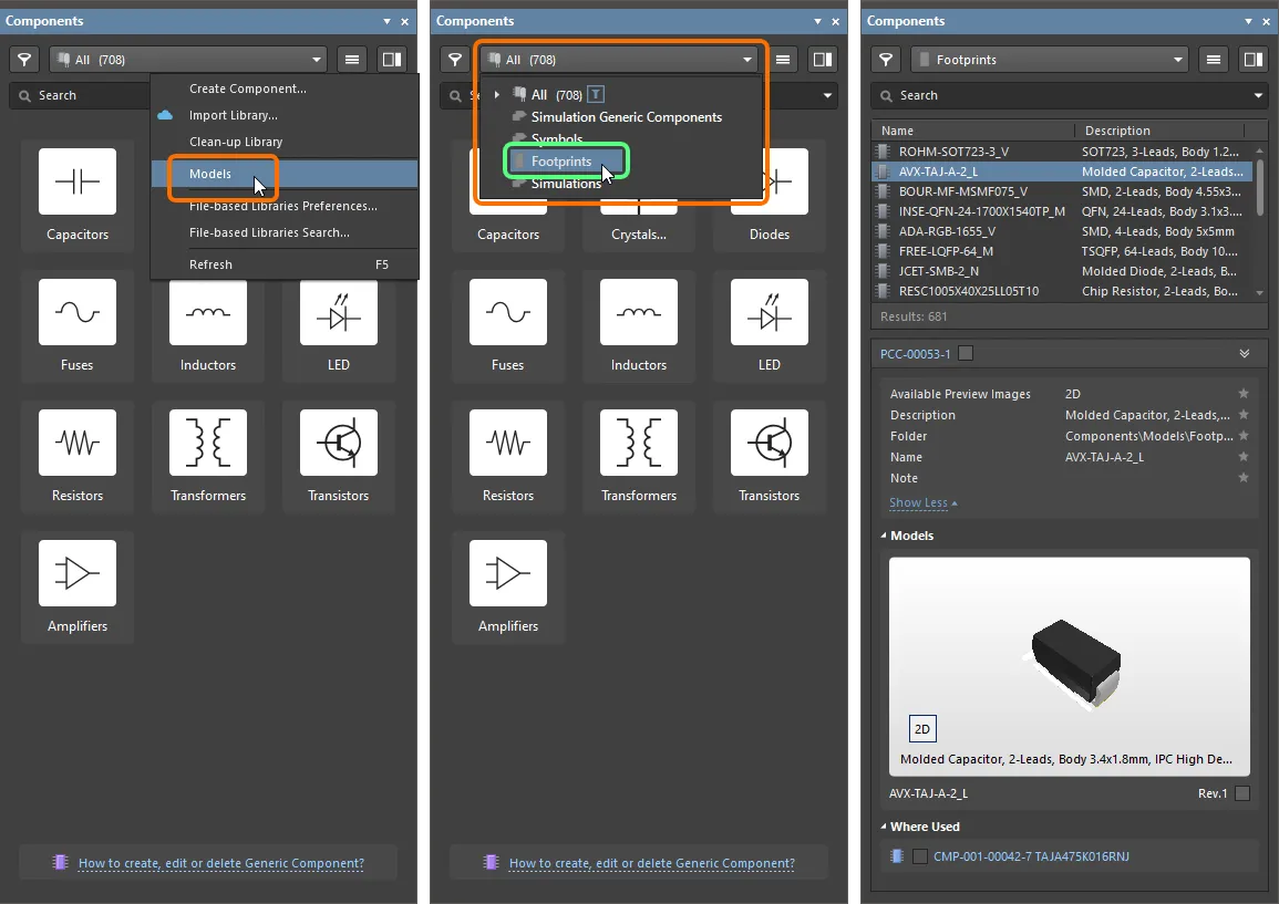
To edit a Workspace Footprint, right-click its entry in the Components panel and select the Edit command. Once again, the temporary editor will open, with the footprint opened for editing. Make changes as required, then save the document into the next revision of the Workspace Footprint.
Updating Related Component
Copy Link
Copied
When you make a change to a Workspace domain model – be it a symbol, footprint model, or simulation model – the moment you save that change into a new revision of the model, any Workspace Components that use that model will become effectively out of date, still using the previous revision. In most cases, you will no doubt want to re-save those Workspace Components, with the respective model links updated to use the latest revisions available. To streamline this process, a Workspace, in conjunction with Altium Designer, facilitates the ability to update related components – at the point of re-saving a Workspace model – after having made any modifications to that model through the direct editing feature.
The option to perform this update to the parent components can be found in the Create Revision dialog that appears when saving the modified Workspace Footprint back to the target Workspace. This option – Update items related to <ModelItemRevision> – is enabled by default.
<ModelItemRevision> is the current revision of the model, that is, the revision currently being used by any related Workspace Components. Once the Workspace model itself is saved, this would naturally be the previous (earlier) revision, and no longer the latest.
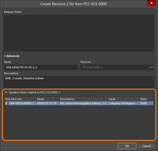
Accessing the option to update related Workspace Components, that are referencing the Workspace Footprint being re-saved.
If you want to keep all related components using the current revision of the Workspace Footprint, disable this option. Only the Workspace model itself will then be saved.
Once you click OK in the Create Revision dialog, the modified footprint is saved back to the Workspace, and its associated temporary editor is closed. All Workspace Components referencing that Workspace Footprint will be re-saved to use its new revision automatically (the next revision of each component is automatically created and the save performed).
- From a designer's perspective, a Workspace Component gathers together all information needed to represent that component across all design domains, within a single entity. It could therefore be thought of as a container in this respect – a 'bucket' into which all domain models and parametric information is stored. In terms of its representation in the various domains, a Workspace Component doesn't contain the Workspace domain models themselves, but rather links to these models. These links are specified when defining the component.
- PCB footprints can also be created in the Workspace as part of importing existing, older generation (SchLib, PcbLib, IntLib, DbLib, SVNDbLib) libraries of components. The interface to this process – the Library Importer – presents an intuitive flow that takes initial selected libraries, and imports them to your Workspace. Learn more about the Library Importer.
- A new Workspace Footprint can also be created when defining a Workspace Component in the Component Editor in its Single Component Editing mode.
- A footprint can also be created as part of a file-based PCB footprint library.
Defining a PCB Footprint
Copy Link
Copied
Footprints are always built on the top side, regardless of which final side of the board they are placed, using the same set of tools and design objects available in the PCB editor. Layer-specific attributes, such as surface mount pads and solder mask definitions, are automatically transferred to appropriate bottom-side layers when you flip the footprint to the other side of the board during component placement.
Design objects can be placed on any layer, however, the outline is normally created on the Top Overlay (silkscreen) layer and the pads on the multi-layer (for thru-hole component pins) or the top signal layer (for surface mount component pins). When you place the footprint on a PCB, all objects that make up the footprint will be assigned to their defined layers.
The footprints shown on this page are only to illustrate the procedures required; they are not dimensionally accurate. Always check the specifications of a new footprint against the manufacturer's datasheet.
Manually Creating a Footprint
Copy Link
Copied
 2D and 3D views of a footprint for a joystick component. The 3D image shows the imported STEP model for the component. Note that the pads and component overlay can be seen below the STEP model.
The typical sequence for manually creating a component footprint is:
- Prepare the design space: define snap options, configure grids and guides - learn more.
- Footprints should be built around the design space reference point at the center of the PCB footprint editor. This reference point is actually the relative origin for the design space and is the point by which the component footprint is picked-up by the cursor in Place and Move operations. Use the J, R shortcut keys to jump directly to the reference point. If you have forgotten to move to the reference point before beginning to build your footprint, you can bring the reference pad to your footprint using the Edit » Set Reference sub-menu commands:
- Pin 1 - set the component reference point to be pin 1 of the component footprint.
- Center - set the component reference point to be the center of the component footprint.
- Location - set the component reference point to a user-defined location.
The chosen point will be set to 0,0 - it becomes the new relative origin and all primitives will have their locations updated relative to this point.
-
Place the pads (Place » Pad) according to the component requirements. After running the Place Pad command but prior to placing the first pad, press the Tab key to open the Properties panel to define all the pad properties, including the pad Designator, Size and Shape, Layer, and Hole Size (for a thru-hole pad). The Designator automatically increments for subsequent pad placements. For a surface mount pad, set the Layer to Top Layer. For a thru-hole pad, set the Layer to Multi-Layer.
Some footprints require pads that have an irregular shape. This can be done using pad objects of Custom Shape. To learn more, refer to the
Customizing a Pad Stack page.
- One of the most important procedures in creating a new component footprint is placing the pads that will be used to solder the component to the PCB. These must be placed in exactly the right positions to correspond to the pins on the physical device.
- Some care should also be exercised when designating pads since it is this property that Altium Designer uses when mapping from pin numbers on the schematic symbol.
- To ensure accurate placement of the pads, consider setting up a grid specifically for the task. Use the Ctrl+G shortcut keys to open the Cartesian Grid Editor dialog and the Q key to toggle the grid from Imperial to Metric.
- To accurately place a pad while moving it with the mouse, use the keyboard arrow keys to move the cursor in current grid increments. Additionally, holding Shift will move in steps of 10 times the grid. The current X, Y location is displayed on the Status bar and also in the Heads Up display. The Heads Up Display contains both the location and the delta from the last click location to the current cursor location. Use the Shift+H shortcut to toggle the Heads Up display on and off. Alternatively, double-click to edit a placed pad and enter the required X and Y locations in the Properties panel.
- To check a distance between two points in the design space, use the Reports » Measure Distance (shortcut Ctrl+M). Follow the prompts on the Status bar.
- Pad-specific attributes, such as solder mask and paste mask, are automatically calculated based on the pad dimensions and applicable mask design rules. While mask settings can be defined manually for each pad, doing so makes it difficult to modify these settings later during the board design process. Typically this is done only when it is not possible to target the pads by design rules. Note that rules are defined in the PCB editor during board design.
- Use tracks, arcs and other primitive objects to define the component outline that appears on the PCB silkscreen on the Top Overlay layer. If the component is flipped to the bottom of the board during placement, the overlay is automatically transferred to the Bottom Overlay layer.
- Place tracks and other primitive objects on a mechanical layer to define extra mechanical detail, such as a placement courtyard. Mechanical layers are general-purpose layers. You should allocate the function of these layers and use them consistently across their footprints.
-
Place 3D Body objects to define the three-dimensional shape of the physical component to be mounted on the PCB.
-
The Designator and Comment strings are automatically added to the footprint’s Overlay layer during placement into the PCB design space. Additional Designator and Comment strings can be included by placing the .Designator and .Comment special strings on a mechanical layer.
When placing Designator and Comment strings, a Layer Pair needs to be defined in the PCB editor. This ensures that the strings will be tied to the side of the board on which the component is mounted and must flip to the other side of the board when the component is flipped. For more information, see the
Handling Special Layer-specific Requirements section below.
-
Define the properties of the footprint (e.g., its name and description) on the Footprint tab of the Properties panel in its Library Options mode (active when no object is selected in the design space, can be accessed using the Tools » Footprint Properties command from the main menus). Refer to the section below to learn more about the options and controls available under the panel's Footprint tab.
For a standardized pad/via definition across all footprints, the Pad/Via library (*.PvLib) can be used for Pad/Via placement.
Preparing the Design Space
The default is to display the grids using dots. If you prefer, grids can be displayed using lines. This is configured in the Grid Editor dialog, accessed by clicking the Properties button in the Properties panel as shown in the image below. Alternatively, press the Ctrl+G shortcut to open the dialog.

In the image, the fine grid is displayed as dots, and the coarse grid is displayed as lines.
Properties Panel
When editing a footprint in the PCB footprint editor and when no design object is currently selected in the design space, the Properties panel presents the Library Options.
The following collapsible sections contain information about the options and controls available under the panel's General tab:
Selection Filter
Copy Link
Copied
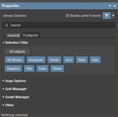
The options in this section of the panel determine which PCB library objects may be selected in the design space.
- All Objects button – select remove object filtering so that all types of objects may be selected.
- Object buttons – toggle each object button to enable/disable the ability to select that object type.
Snap Options
Copy Link
Copied
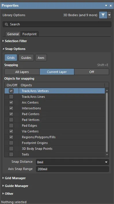
- Grids – used to toggle whether the cursor will snap to the active design space grid. When this option is enabled the cursor will pull, or snap, to the nearest snap grid location. The active snap grid is displayed on the Status bar, and in the PCB editor Heads Up display (Shift+H shortcut to toggle on/off).
- Guides – used to toggle whether the cursor will snap to manually placed linear or point Snap Guides. A Snap Guide will override the Snap Grid.
- Axes – used to toggle whether the cursor will axially align (in either the X or Y direction) to the enabled Objects for snapping. The Axis Snap Range defines the distance within which X or Y axial alignment will occur. A dynamic alignment guideline is displayed when alignment is achieved from the current cursor location to the axially-aligned object snap point (hotspot).
- Snapping – select directly or use the Shift+E shortcut to select whether you want to snap to objects on:
- All Layers – enable this option to allow the cursor to snap to any electrical object on any visible layer.
- Current Layer – enable this option to allow the cursor to only recognize and snap to objects placed on the currently selected layer.
- Off – enable this option to turn off snapping to hotspots.
- Objects for snapping
- On/Off – check to enable snapping for the desired objects.
- Objects – a list of the available objects.
- Snap Distance – when the cursor is within this distance from an enabled object snap point (and snapping is enabled for the active layer), the cursor will snap to that point.
- Axis Snap Range – when the cursor is axially aligned and within this distance from an enabled object snap point (and the Axes button is enabled), a dynamic guideline will display to indicate that alignment has been achieved.
Grid Manager
Copy Link
Copied
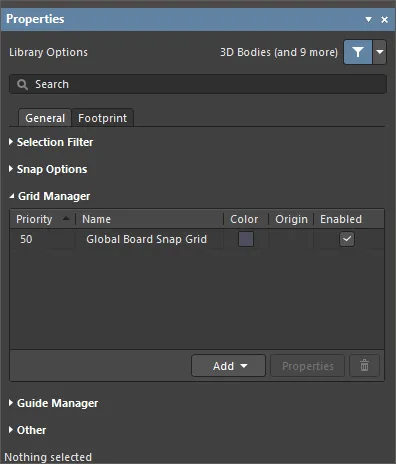
- Grid Manager – where local customized grids can be defined and managed, as well as the default Snap Grid for the board.
- Priority – in the design space, priority is distinguished by drawing order. The highest priority grid (priority
1) will be drawn in front of all other grids, then the grid with priority level 2, etc., down to the default Global Board Snap Grid, which is drawn behind all other custom grids.
- Name – displays the name of the grid.
- Color – click to open a drop-down to set/change the color of the associated grid.
- Enabled – check to enable the associated grid.
- Add
- Add Cartesian Grid – click to add a Cartesian grid.
- Add Polar Grid – click to add a Polar grid. Polar grids enable you to more easily design non-rectangular features and boards.
- Properties – click to open the respective grid editor dialog (Cartesian Grid Editor or Polar Grid Editor) to modify properties for the selected grid.
-
 – click to delete the currently selected grid.
Guide Manager
Copy Link
Copied
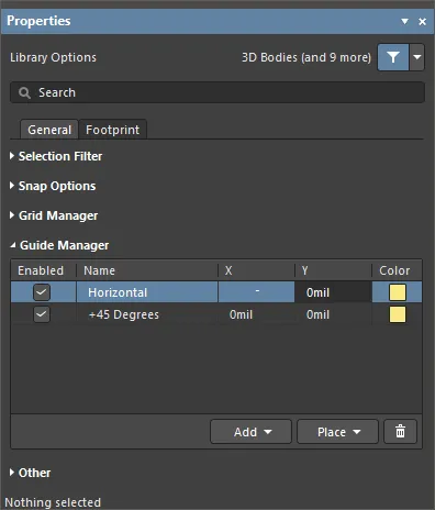
- Guide Manager – where a range of manual Snap Guides and Snap Points for the board can be defined and managed.
- Add – click to add a new snap guide or snap point. Choose the corresponding command for the required guide type from the associated menu; an entry for the new guide/point will be added to the grid. The following guide types are available:
Add Horizontal Guide – use this command to add a horizontal guideline at the desired Y-coordinate location in the design space.Add Vertical Guide – use this command to add a vertical guideline at the desired X-coordinate location in the design space.Add +45 Guide – use this command to add a 45 degree (y=x) guideline that passes through the desired X,Y coordinate location in the design space.Add -45 Guide – use this command to add a -45 degree (y=-x) guideline that passes through the desired X,Y coordinate location in the design space.Add Snap Point – use this command to add a point snap guide. This is a hotspot that you manually mark within the confines of the default snap grid. During an interactive process such as placing or moving an object, that objects' hotspot will 'snap' to a point snap guide when it passes into close proximity with it.
- Place – click to place a guide. Select the guide type from the drop-down:
Place Horizontal Guide – use this command to place a horizontal guideline at the desired Y-coordinate location in the design space.Place Vertical Guide – use this command to place a vertical guideline at the desired X-coordinate location in the design space.Place +45 Guide – use this command to place a 45 degree (y=x) guideline that passes through the desired X,Y coordinate location in the design space.Place -45 Guide – use this command to place a -45 degree (y=-x) guideline that passes through the desired X,Y coordinate location in the design space.Place Snap Point – use this command to place a point snap guide. This is a hotspot that you manually mark within the confines of the default snap grid. During an interactive process such as placing or moving an object, that objects' hotspot will 'snap' to a point snap guide when it passes into close proximity with it.
-
 – click to delete the currently selected guide.
Other
Copy Link
Copied
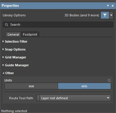
- Units – use to select the default measurement units for the current PCB Library document. Default units are used to display any distance-related information on screen or in reports. The default units are always used if a unit's suffix (mm or mil) is not entered when specifying any distance-related information.
- Route Tool Path – use the drop-down to choose the mechanical layer (from all those currently enabled for use in the design) on which to define the route tool path for the board.
The following collapsible sections contain information about the options and controls available under the panel's Footprint tab:
When a design object is selected, the panel will present options specific to that object type. The following table lists the object types available for placement within the library design space – click a link to access the properties page for that object.
Creating a Footprint Using the IPC Compliant Footprint Wizard
Copy Link
Copied
The IPC Compliant Footprint Wizard generates a PCB footprint that is truly compliant with Revision B of the IPC standard 7351 - Generic Requirements for Surface Mount Design and Land Pattern Standard. Rather than working directly from footprint dimensions (as the Footprint Wizard does), the IPC Compliant Footprint Wizard uses dimensional information from the component itself, and then calculates suitable pad and other footprint properties in accordance with the algorithms released by the IPC.
Instead of requiring you to enter the properties of the pads and tracks that are used to define the footprint, the Wizard takes the actual component dimensions as its inputs. Based on the formulas developed for the IPC-7351 standard, the Wizard then generates the footprint using standard Altium Designer objects, such as pads and tracks.
This dialog is compliant with Revision B of the IPC standard 7351 - Generic Requirements for Surface Mount Design and Land Pattern Standard. IPC-7351B was released in 2010 and supersedes IPC-7351A (which was released in 2007).
Functionality is provided courtesy of the IPC Footprint Generator extension (a Software Extension).

The IPC Footprint Generator extension
The IPC Footprint Generator functionality can only be accessed provided the IPC Footprint Generator extension is installed as part of your Altium Designer installation. This extension is installed by default when installing the software, but in case of inadvertent uninstall can be found on the Purchased tab of the Extensions and Updates page (click on the  control at the top right of the design space then choose Extensions and Updates from the menu). If reinstalling, remember to restart Altium Designer once the extension has been successfully downloaded and installed.
 One of the supported packages in the IPC Compliant Footprint Wizard is the DPAK (Transistor Outline).
Some of the IPC Compliant Footprint Wizard features include:
- Overall packaging dimensions, pin information, heel spacing, solder fillets, and tolerances can be entered and immediately viewed.
- Mechanical dimensions, such as Courtyard, Assembly, and Component (3D) Body Information, can be entered.
- The Wizard is re-entrant and allows reviewing and making adjustments easy. Previews of the footprint are shown at every stage.
- The name and description for the footprint are automatically suggested, but can be changed to suit organizational requirements.
- In accordance with the IPC standard, the Wizard supports three footprint variants (_L, _N, _M), each tailored to suit a different board density.
- The Finish button can be pressed at any stage to generate the currently previewed footprint. If you click Finish before completing the entire Wizard, the footprint will be created using the system defaults for the component type you selected.
Selecting the Component Type

Choose the family of components for which you want to create a footprint on the Select Component Type page.
Click on the component type desired. The preview region on the right-hand side of the Wizard dynamically changes to show the currently selected component and also states the type of packages that are allowed to be generated.
The following table lists the component types and packages that are supported in the Wizard.
|
Name
|
Description
|
Included Packages
|
| BGA |
Ball Grid Array |
BGA, CGA |
| BQFP |
Bumpered Quad Flat Pack |
BQFP |
| CAPAE |
Electrolytic Aluminum Capacitor |
CAPAE |
| CFP |
Ceramic Dual Flat Pack - Trimmed and formed Gullwing Leads |
CFP |
| Chip Array |
Chip Array |
Chip Array |
| DFN |
Dual Flat No-lead |
DFN |
| CHIP |
Chip Components, 2-Pins |
Capacitor, Inductor, Resistor |
| CQFP |
Ceramic Quad Flat Pack - Trimmed and formed Gullwing Leads |
CQFP |
| DPAK |
Transistor Outline |
DPAK |
| LCC |
Leadless Chip Carrier |
LCC |
| LGA |
Land Grid Array |
LGA |
| MELF |
MELF Components, 2-Pins |
Diode, Resistor |
| MOLDED |
Molded Components, 2-Pins |
Capacitor, Inductor, Diode |
| PLCC |
Plastic Leaded Chip Carrier, Square - J Leads |
PLCC |
| PQFN |
Pullback Quad Flat No-Lead |
PQFN |
| PQFP |
Plastic Quad Flat Pack |
PQFP, PQFP Exposed Pad |
| PSON |
Pullback Small Outline No-Lead |
PSON |
| QFN |
Quad Flat No-Lead |
QFN, LLP |
| QFN-2ROW |
Quad Flat No-Lead, 2 Rows, Square |
Double Row QFN |
| SODFL |
Small Outline Diode, Flat Lead |
SODFL |
| SOIC |
Small Outline Integrated Package, 1.27mm Pitch - Gullwing Leads |
SOIC, SOIC Exposed Pad |
| SOJ |
Small Outline Package - J Leads |
SOJ |
| SON |
Small Outline Non-Lead |
SON, SON Exposed Pad |
| SOP, TSOP |
Small Outline Package - Gullwing Leads |
SOP, TSOP, TSSOP |
| SOT143/343 |
Small Outline Transistor |
SOT143, SOT343 |
| SOT223 |
Small Outline Transistor |
SOT223 |
| SOT23 |
Small Outline Transistor |
3-Leads, 5-Leads, 6-Leads |
| SOT89 |
Small Outline Transistor |
SOT89 |
| SOTFL |
Small Outline Transistor, Flat Lead |
3-Leads, 5-Leads, 6-Leads |
| WIRE WOUND |
Precision Wire Wound Inductor, 2-Pins |
Inductor |
Preview Region
On the following pages for each component type, the
Preview region dynamically updates to show new location, size, etc., for several settings. In the
Preview region, you can click

or

to toggle between 2D and 3D preview images.
3D STEP Models
Previewing 3D STEP Models
If desired, you can see a preview of the 3D STEP model before generating the model. Click Generate STEP Model Preview on any page in the Wizard after selecting the component type to see a preview of the 3D STEP model in the Preview region.
The default setting for the files that are created when 3D STEP models are generated is Embedded STEP files. If these default settings are correct for your needs, you can click Finish to exit the IPC® Compliant Footprint Wizard and generate the 3D STEP model.
The subsequent pages of the Wizard change depending upon the component type you selected. Find your component type in the following list then click on the link to access the information regarding that component type.
BGA
Copy Link
Copied
BGA
BGA Package Dimensions
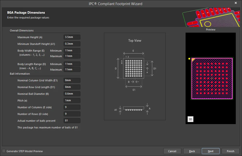
Use the BGA Package Dimensions page to enter the required package values for Overall Dimensions and Ball Information.
BGA Package Layout Options

Use the BGA Package Layout Options page to define the basic ball layout by adding or removing balls and changing the grid type.
The Add Balls to Cavity Border selections are only accessible if Selectively Depopulated is selected from the drop-down.
Select the grid type from the drop-down. Selections include Plain Grid or Staggered Grid.
Select the matrix type from the drop-down. Selections include Full Matrix, Perimeter, Thermally Enhanced, and Selectively Depopulated.
- If Full Matrix is selected, none of the other options of the region are available.
- If Perimeter is selected, only Cavity Size is accessible for updating.
- If Thermally Enhanced is selected, only Cavity Size and Size of Thermal Array are accessible for updating.
- If Selectively Depopulated is selected, all areas, including Add Balls to Cavity Border are accessible for updating.
BGA Pads Diameter

The BGA Pads Diameter page is used to specify the pad diameter of the footprint. The pad diameter is determined using the following methods:
- Select Use Maximum Material Condition (MMC) to use the largest pad size (IPC recommended) for the given ball diameter.
- Select Use Least Material Condition (LMC) to use the smallest pad size (IPC recommended) for the given ball diameter.
- Select Reduce from nominal ball diameter (B) in percent by to define a percentage reduction of the ball diameter then enter the desired percentage value in the textbox.
The pad diameter will be - this statement is dynamically updated to show the current value based on the above selections.
BGA Silkscreen Dimensions

The BGA Silkscreen Dimensions page displays the inferred silkscreen dimensions using the package dimensions previously defined. You can further define the silkscreen dimensions by entering a new value for the Silkscreen Line Width.
Enable the Use calculated silkscreen dimensions to use the displayed values or disable the checkbox and enter the desired new values in the textboxes.
BGA Courtyard, Assembly and Component Body Information
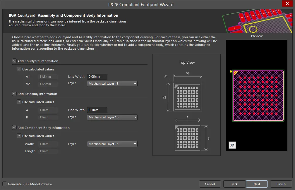
The BGA Courtyard, Assembly and Component Body Information page displays the inferred mechanical dimensions using the package dimensions previously defined.
Enable the Add Courtyard Information and Add Assembly Information to add courtyard and assembly information to the component drawing. For each, you can use the IPC calculated dimensions or enter new values directly in the textboxes. If desired, enter a new Line Width directly in the textbox. You can also select the mechanical layer for courtyard and assembly by using the drop-down next to Layer and selecting the desired mechanical layer.
A component body contains the volumetric information corresponding to the package dimensions. Enable Add Component Body Information to include this information. You can also select the mechanical layer for the component body by using the drop-down next to Layer and selecting the desired mechanical layer.
BQFP
Copy Link
Copied
BQFP
BQFP Package Overall Dimensions
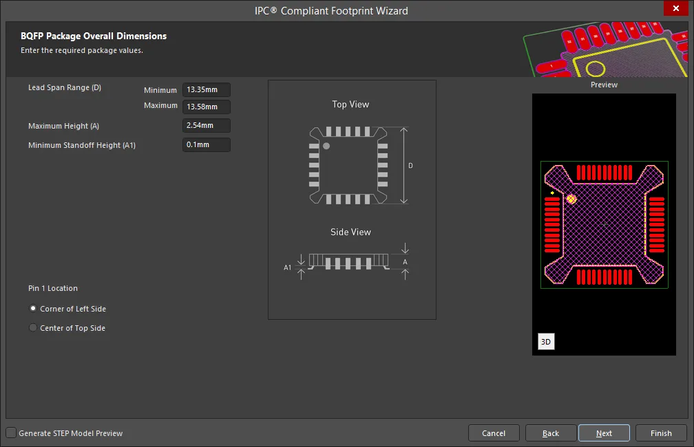
Use the BQFP Package Overall Dimensions page to set the package values.
Enter the Lead Span Range (Minimum and Maximum), Maximum Height, and Minimum Standoff Height using the textboxes to the right of each option. Use the diagram to the right as a guide for each measurement.
Set the Pin 1 Location by selecting either Corner of Left Side or Center of Top Side. The Preview region is dynamically updated to show the Pin location.
BQFP Package Pin Dimensions

Enter the required values for the package pin dimensions on the BQFP Package Pin Dimensions page.
Enter the Lead Width Range, Lead Length Range, Pitch, Body Length Range, and Number of pins.
BQFP Package Heel Spacing

Set the desired heel spacing values on the BQFP Package Heel Spacing page. The minimum heel spacing is calculated by subtracting twice the Maximum Lead Length Range from the Minimum Body Width that were set on the previous page. The maximum heel spacing is calculated by adding the tolerance on the inner distance between the heels of the opposing rows of leads to the minimum heel spacing.
Enable the Use calculated values checkbox to use the values currently displayed or enter values directly in the textboxes for S Minimum and S Maximum.
BQFP Solder Fillets
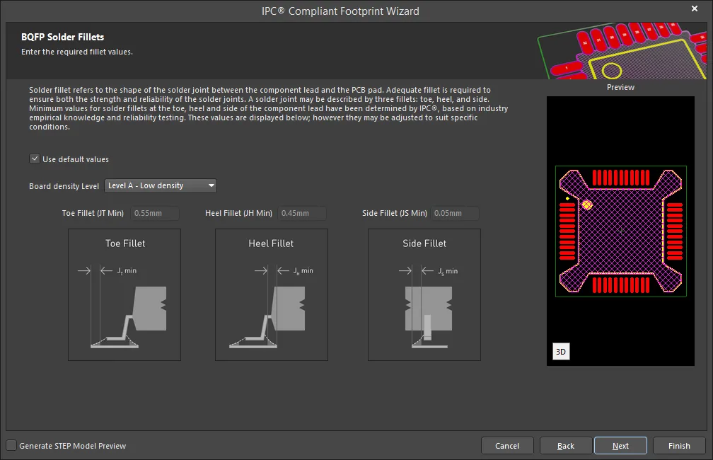
Set the required solder fillet values on the BQFP Solder Fillets page. Solder fillet refers to the shape of the solder joint between the component lead and the PCB pad. Adequate fillet is required to ensure both the strength and reliability of the solder joints. A solder joint may be described by three fillets: toe, heel, and side.
Minimum values for solder fillets at the toe, heel and side of the component lead have been determined by IPC based on industry empirical knowledge and reliability testing. Enable Use default values to use the values displayed or you can adjust them to suit your specific needs.
Use the Board density Level drop-down to select the desired board density. Choose from Level A - Low density, Level B - Medium density, and Level C - High density. The Preview region is dynamically updated to show your changes.
To update the values for Toe Fillet (JT Min), Heel Fillet (JH Min), and Side Fillet (JS Min), the Use default values option must be disabled. Enter the new values directly in the textboxes.
BQFP Component Tolerances
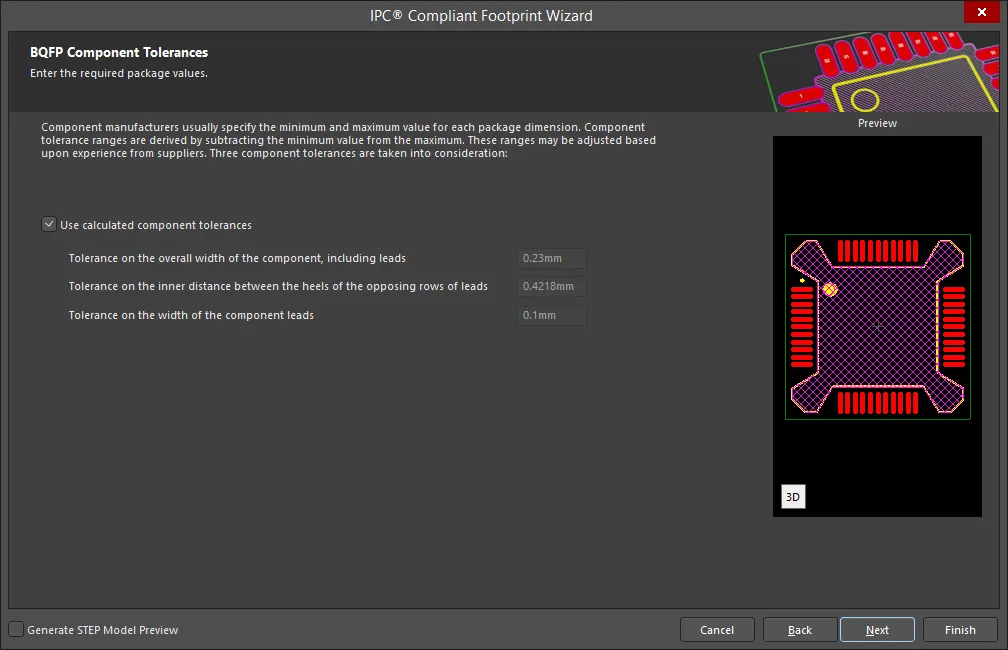
Enter the required values for component tolerances on the BQFP Component Tolerances page.
Component manufacturers usually specify the minimum and maximum value for each package dimension. Component tolerance ranges are derived by subtracting the minimum value from the maximum value. You can adjust three of these ranges based upon experience.
If the displayed values are correct for your current situation, enable the Use calculated component tolerances textbox. If the tolerance values need to be adjusted, ensure Use calculated component tolerances is disabled then enter the new values directly in the textboxes next to Tolerance on the overall width of the component, including leads, Tolerance on the inner distance between the heels of the opposing rows of leads, and/or Tolerance on the width of the component leads.
BQFP IPC Tolerances
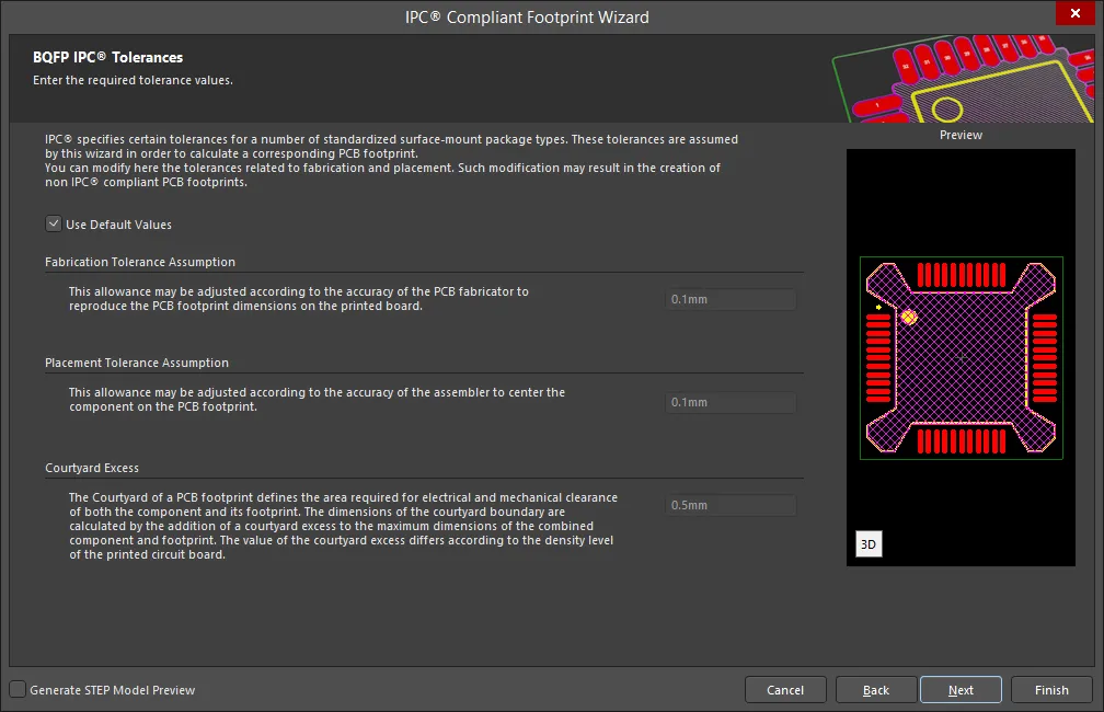
IPC specifies certain tolerances for a number of standardized surface-mount package types. These tolerances are assumed by the Wizard in order to calculate a corresponding PCB footprint. You can modify the tolerances related to fabrication and placement on the BQFP IPC Tolerances page. Enable Use Default Values to accept the displayed values. You can change the values for Fabrication Tolerance Assumption, Placement Tolerance Assumption, and Courtyard Excess by entering the new values directly in the textboxes.
Modifying the IPC Tolerances may result in PCB footprints that are not IPC compliant.
BQFP Footprint Dimensions

The BQFP Footprint Dimensions page displays the inferred footprint dimensions using the package dimensions previously defined. To use the displayed values, enable Use calculated footprint values or enter new values for Pad Dimensions (X and Y), and Pad Spacing. Select the correct Pad Shape, either Rounded or Rectangular.
BQFP Silkscreen Dimensions
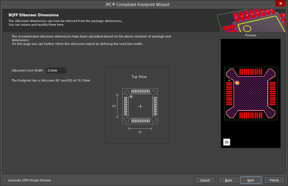
The BQFP Silkscreen Dimensions page displays the inferred silkscreen dimensions using the package dimensions previously defined. You can further define the silkscreen dimensions by entering a new value for the Silkscreen Line Width.
BQFP Courtyard, Assembly and Component Body Information

The BQFP Courtyard, Assembly and Component Body Information page displays the inferred mechanical dimensions using the package dimensions previously defined.
Enable the Add Courtyard Information and Add Assembly Information to add courtyard and assembly information to the component drawing. For each, you can use the IPC calculated dimensions or enter new values directly in the textboxes. If desired, enter a new Line Width directly in the textbox. You can also select the mechanical layer for Courtyard, Assembly, and Component Body by using the drop-down next to Layer and selecting the desired mechanical layer.
A component body contains the volumetric information corresponding to the package dimensions. Enable Add Component Body Information to include this information.
CAPAE
Copy Link
Copied
CAPAE
CAPAE Component Package Dimensions
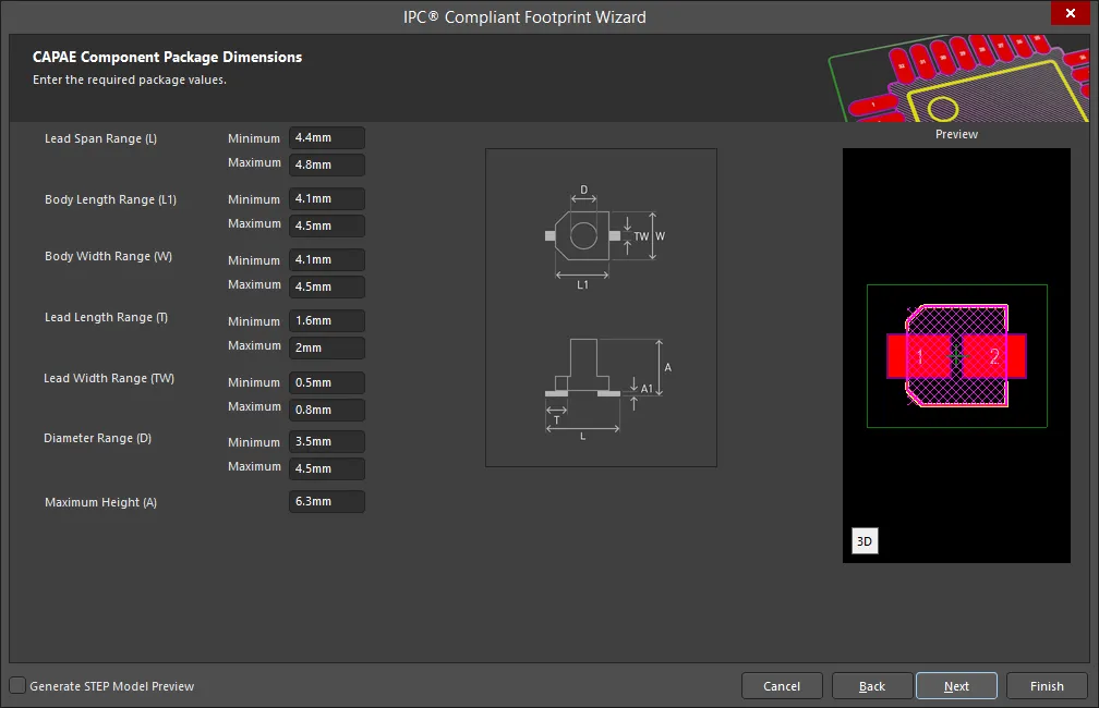
Enter the required values for the package dimensions on the CAPAE Component Package Dimensions page.
Enter the Lead Span Range, Body Length Range, Body Width Range, Lead Length Range, Lead Width Range, Diameter Range, and Maximum Height.
CAPAE Component Package Heel Spacing

Set the desired heel spacing values on the CAPAE Component Package Heel Spacing page. The maximum heel spacing is calculated by adding the tolerance on the inner distance between the heels of the opposing rows of leads to the minimum heel spacing.
Enable the Use calculated values checkbox to use the values currently displayed or enter values directly in the textboxes for S Minimum and S Maximum.
CAPAE Component Solder Fillets
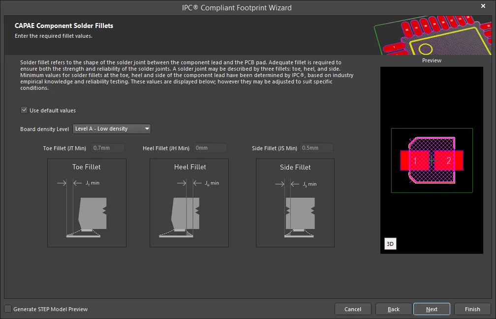
Set the required solder fillet values on the CAPAE Component Solder Fillets page. Solder fillet refers to the shape of the solder joint between the component lead and the PCB pad. Adequate fillet is required to ensure both the strength and reliability of the solder joints. A solder joint may be described by three fillets: toe, heel, and side.
Minimum values for solder fillets at the toe, heel and side of the component lead have been determined by IPC based on industry empirical knowledge and reliability testing. Enable Use default values to use the values displayed or you can adjust them to suit your specific needs.
Use the Board density Level drop-down to select the desired board density. Choose from Level A - Low density, Level B - Medium density, and Level C - High density. The Preview region is dynamically updated to show your changes.
To update the values for Toe Fillet (JT Min), Heel Fillet (JH Min), and Side Fillet (JS Min), the Use default values option must be disabled. Enter the new values directly in the textboxes.
CAPAE Component Component Tolerances

Enter the required values for component tolerances on the CAPAE Component Component Tolerances page.
Component manufacturers usually specify the minimum and maximum value for each package dimension. Component tolerance ranges are derived by subtracting the minimum value from the maximum value. You can adjust three of these ranges based upon experience.
If the displayed values are correct for your current situation, enable the Use calculated component tolerances textbox. If the tolerance values need to be adjusted, ensure Use calculated component tolerances is disabled then enter the new values directly in the textboxes next to Tolerance on the overall width of the component, including leads, Tolerance on the inner distance between the heels of the opposing rows of leads, and/or Tolerance on the width of the component leads.
CAPAE Component IPC Tolerances

IPC specifies certain tolerances for a number of standardized surface-mount package types. These tolerances are assumed by the Wizard in order to calculate a corresponding PCB footprint. You can modify the tolerances related to fabrication and placement on the CAPAE Component IPC Tolerances page. Enable Use Default Values to accept the displayed values. You can change the values for Fabrication Tolerance Assumption, Placement Tolerance Assumption, and Courtyard Excess by entering the new values directly in the textboxes.
Modifying the IPC Tolerances may result in PCB footprints that are not IPC compliant.
CAPAE Component Footprint Dimensions

The CAPAE Component Footprint Dimensions page displays the inferred footprint dimensions using the package dimensions previously defined. To use the displayed values, enable Use calculated footprint values or enter new values for Pad Dimensions (X and Y), and Pad Spacing.
CAPAE Component Silkscreen Dimensions
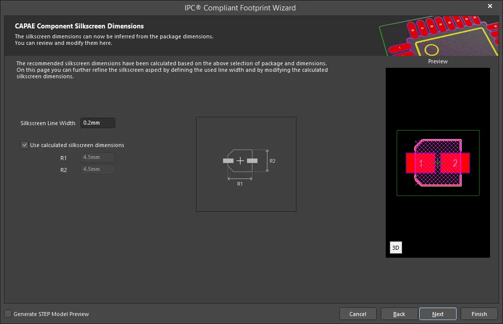
The CAPAE Component Silkscreen Dimensions page displays the inferred silkscreen dimensions using the package dimensions previously defined. You can further define the silkscreen dimensions by entering a new value for the Silkscreen Line Width. Enable Use calculated silkscreen dimensions to use the values displayed or disable the option and enter new desired values.
CAPAE Component Courtyard, Assembly and Component Body Information

The CAPAE Component Courtyard, Assembly and Component Body Information page displays the inferred mechanical dimensions using the package dimensions previously defined.
Enable Add Courtyard Information and Add Assembly Information to add courtyard and assembly information to the component drawing. For each, you can use the IPC calculated dimensions or enter new values directly in the textboxes. If desired, enter a new Line Width directly in the textbox. You can also select the mechanical layer for courtyard and assembly by using the drop-down next to Layer and selecting the desired mechanical layer.
A component body contains the volumetric information corresponding to the package dimensions. Enable Add Component Body Information to include this information. Enable Use calculated values to use the values displayed or disable the option and enter new desired values. You can also select the mechanical layer for the component body by using the drop-down next to Layer and selecting the desired mechanical layer.
CFP
Copy Link
Copied
CFP
CFP Package Overall Dimensions

Use the CFP Package Overall Dimensions page to set the package values.
Enter the Maximum Body Width, Maximum Body Length, Maximum Height, Minimum Standoff Height, and Absent Pins using the textboxes to the right of each option. Use the diagram to the right as a guide for each measurement.
CFP Package Pin Dimensions
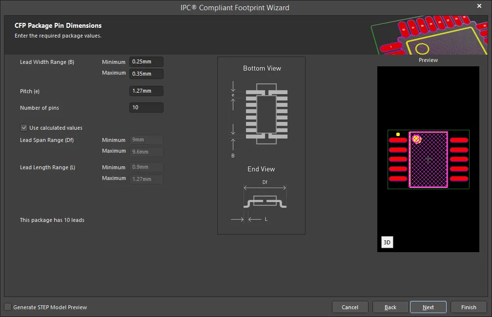
Enter the required values for the package pin dimensions on the CFP Package Pin Dimensions page.
Enter the Lead Width Range, Pitch, and Number of pins. Enable Use calculated values to accept the displayed values or disable the checkbox and enter new values for Lead Span Range and Lead Length Range.
CFP Package Heel Spacing

Set the desired heel spacing values on the CFP Package Heel Spacing page.
Enable the Use calculated values checkbox to use the values currently displayed or enter values directly in the textboxes for S Minimum and S Maximum.
CFP Solder Fillets
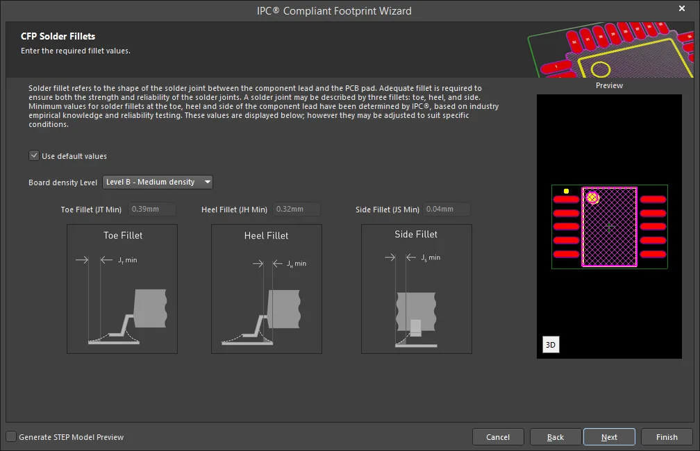
Set the required solder fillet values on the CFP Solder Fillets page. Solder fillet refers to the shape of the solder joint between the component lead and the PCB pad. Adequate fillet is required to ensure both the strength and reliability of the solder joints. A solder joint may be described by three fillets: toe, heel, and side.
Minimum values for solder fillets at the toe, heel and side of the component lead have been determined by IPC based on industry empirical knowledge and reliability testing. Enable Use default values to use the values displayed or you can adjust them to suit your specific needs.
Use the Board density Level drop-down to select the desired board density. Choose from Level A - Low density, Level B - Medium density, and Level C - High density. The Preview region is dynamically updated to show your changes.
To update the values for Toe Fillet (JT Min), Heel Fillet (JH Min), and Side Fillet (JS Min), the Use default values option must be disabled. Enter the new values directly in the textboxes.
CFP Component Tolerances
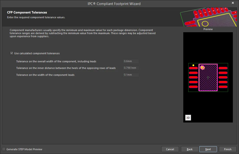
Enter the required values for component tolerances on the CFP Component Tolerances page.
Component manufacturers usually specify the minimum and maximum value for each package dimension. Component tolerance ranges are derived by subtracting the minimum value from the maximum value. You can adjust three of these ranges.
If the displayed values are correct for your current situation, enable the Use calculated component tolerances textbox. If the tolerance values need to be adjusted, ensure Use calculated component tolerances is disabled then enter the new values directly in the textboxes next to Tolerance on the overall width of the component, including leads, Tolerance on the inner distance between the heels of the opposing rows of leads, and Tolerance on the width of the component leads.
CFP IPC Tolerances
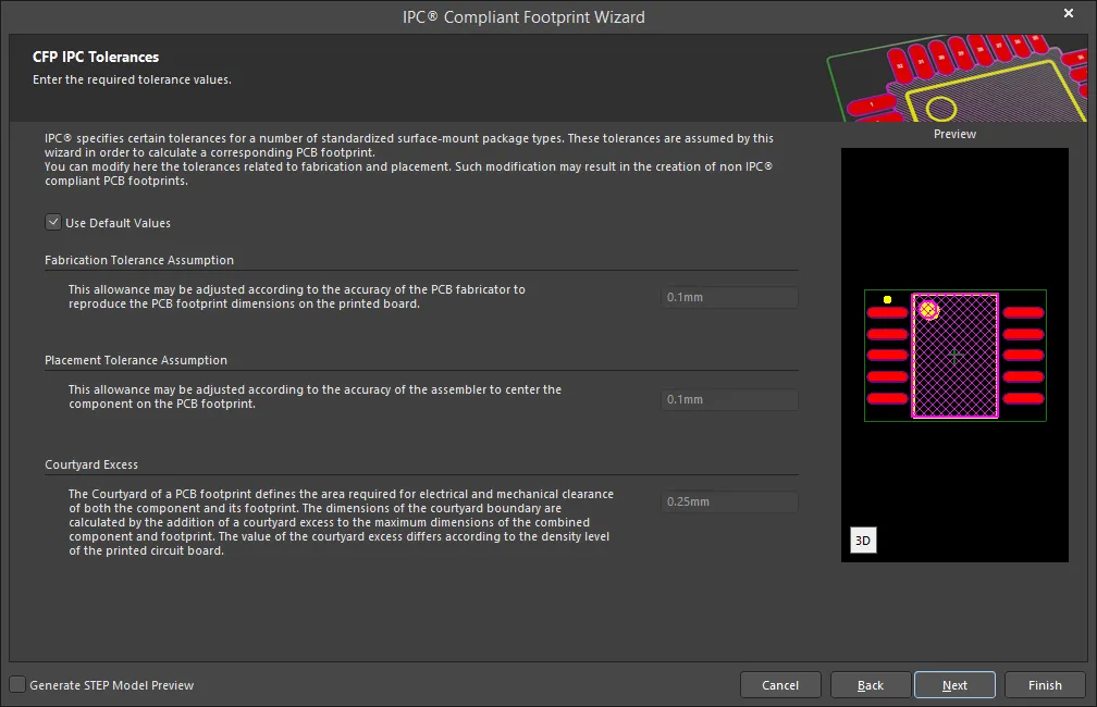
IPC specifies certain tolerances for a number of standardized surface-mount package types. These tolerances are assumed by the Wizard in order to calculate a corresponding PCB footprint. You can modify the tolerances related to fabrication and placement on the CFP IPC Tolerances page. Enable Use Default Values to accept the displayed values. You can change the values for Fabrication Tolerance Assumption, Placement Tolerance Assumption, and Courtyard Excess by entering the new values directly in the textboxes.
Modifying the IPC Tolerances may result in PCB footprints that are not IPC compliant.
CFP Footprint Dimensions
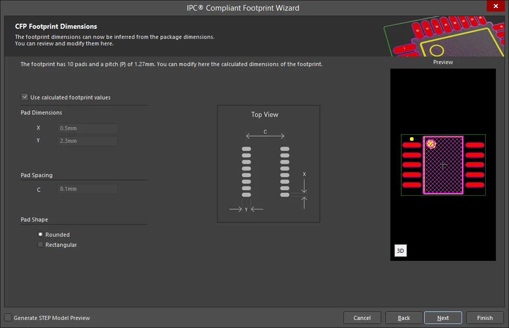
The CFP Footprint Dimensions page displays the inferred footprint dimensions using the package dimensions previously defined. To use the displayed values, enable Use calculated footprint values or enter new values for Pad Dimensions (X and Y), Pad Spacing. Select either Rounded or Rectangular for the Pad Shape.
CFP Silkscreen Dimensions

The CFP Silkscreen Dimensions page displays the inferred silkscreen dimensions using the package dimensions previously defined. You can further define the silkscreen dimensions by entering a new value for the Silkscreen Line Width. Enable Use calculated silkscreen dimensions to use the values displayed or disable the option and enter the desired values.
CFP Courtyard, Assembly and Component Body Information
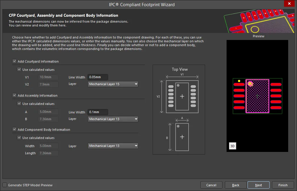
The CFP Courtyard, Assembly and Component Body Information page displays the inferred mechanical dimensions using the package dimensions previously defined.
Enable Add Courtyard Information and Add Assembly Information to add courtyard and assembly information to the component drawing. For each, you can use the IPC calculated dimensions or enter new values directly in the textboxes. If desired, enter a new Line Width directly in the textbox. You can also select the mechanical layer for courtyard and assembly by using the drop-down next to Layer and selecting the desired mechanical layer.
A component body contains the volumetric information corresponding to the package dimensions. Enable Add Component Body Information to include this information. Enable Use calculated values to use the values displayed or disable the option and enter new desired values. You can also select the mechanical layer for the component body by using the drop-down next to Layer and selecting the desired mechanical layer.
Chip Array
Copy Link
Copied
Chip Array
Chip Array Package Dimensions
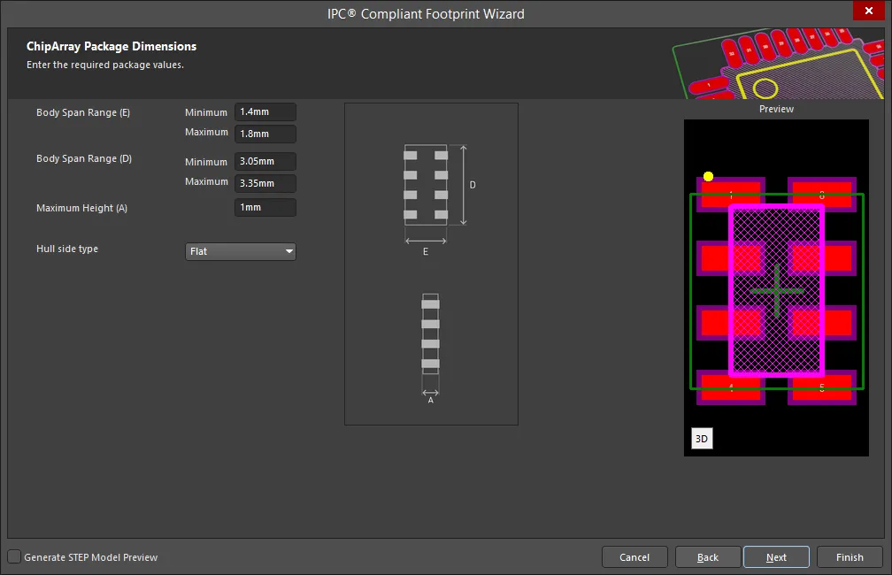
Use the ChipArray Package Dimensions page to set the package values.
Enter the Body Span Range(s) and Maximum Height. Use the drop-down to select the Hull side type: Flat, Concave, ConvexE, or ConvexS.
Chip Array Package Pin Dimensions

Enter the required values for the package pin dimensions on the ChipArray Package Pin Dimensions page.
Enter the Lead Width Range, Lead Length Range, Pitch, and Number of pins.
Chip Array Package Heel Spacing

Set the desired heel spacing values on the ChipArray Package Heel Spacing page.
Enable the Use calculated values checkbox to use the value currently displayed or enter a new value directly in the textboxes for Smax.
Chip Array Solder Fillets
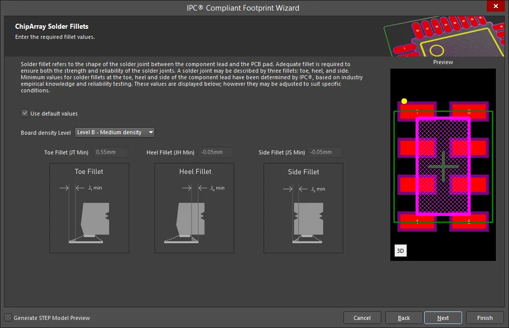
Set the required solder fillet values on the ChipArray Solder Fillets page. Solder fillet refers to the shape of the solder joint between the component lead and the PCB pad. Adequate fillet is required to ensure both the strength and reliability of the solder joints. A solder joint may be described by three fillets: toe, heel, and side.
Minimum values for solder fillets at the toe, heel and side of the component lead have been determined by IPC based on industry empirical knowledge and reliability testing. Enable Use default values to use the values displayed or you can adjust them to suit your specific needs.
Use the Board density Level drop-down to select the desired board density. Choose from Level A - Low density, Level B - Medium density, and Level C - High density. The Preview region is dynamically updated to show your changes.
To update the values for Toe Fillet (JT Min), Heel Fillet (JH Min), and Side Fillet (JS Min), the Use default values option must be disabled. Enter the new values directly in the textboxes.
Chip Array IPC Tolerances

IPC specifies certain tolerances for a number of standardized surface-mount package types. These tolerances are assumed by the Wizard in order to calculate a corresponding PCB footprint. You can modify the tolerances related to fabrication and placement on the ChipArray IPC Tolerances page. Enable Use Default Values to accept the displayed values. You can change the values for Fabrication Tolerance Assumption, Placement Tolerance Assumption, and Courtyard Excess by entering the new values directly in the textboxes.
Modifying the IPC Tolerances may result in PCB footprints that are not IPC compliant.
Chip Array Footprint Dimensions
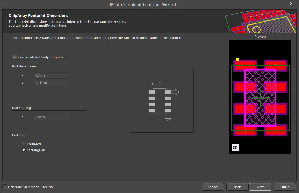
The ChipArray Footprint Dimensions page displays the inferred footprint dimensions using the package dimensions previously defined. To use the displayed values, enable Use calculated footprint values or enter new values for Pad Dimensions (X and Y), Pad Spacing. Select either Rounded or Rectangular for the Pad Shape.
Chip Array Courtyard, Assembly and Component Body Information
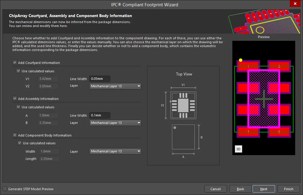
The ChipArray Courtyard, Assembly and Component Body Information page displays the inferred mechanical dimensions using the package dimensions previously defined.
Enable Add Courtyard Information and Add Assembly Information to add courtyard and assembly information to the component drawing. For each, you can use the IPC calculated dimensions or enter new values directly in the textboxes. If desired, enter a new Line Width directly in the textbox. You can also select the mechanical layer for courtyard and assembly by using the drop-down next to Layer and selecting the desired mechanical layer.
A component body contains the volumetric information corresponding to the package dimensions. Enable Add Component Body Information to include this information. Enable Use calculated values to use the values displayed or disable the option and enter new desired values. You can also select the mechanical layer for the component body by using the drop-down next to Layer and selecting the desired mechanical layer.
Chip Array Silkscreen Dimensions
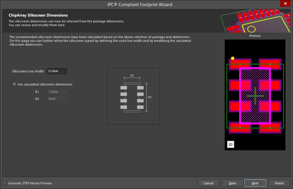
The ChipArray Silkscreen Dimensions page displays the inferred silkscreen dimensions using the package dimensions previously defined. You can further define the silkscreen dimensions by entering a new value for the Silkscreen Line Width. Enable Use calculated silkscreen dimensions to use the values displayed or disable the option and enter the desired values.
DFN
Copy Link
Copied
DFN
DFN Package Overall Dimensions

Use the DFN Package Overall Dimensions page to set the package values.
Enter the Body Width Range, Body Length Range, Maximum Height, and Minimum Standoff Height. Use the drop-down to select the Package Type: DFN 2-Lead, DFN 3-Lead, or DFN 4-Lead.
DFN Package Pin Dimensions
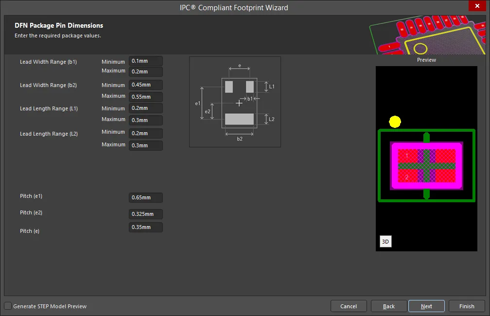
Enter the required values for the package pin dimensions on the DFN Package Pin Dimensions page.
Enter the Lead Width Range(s), Lead Length Range(s), and Pitch(es).
DFN Solder Fillets Dimensions
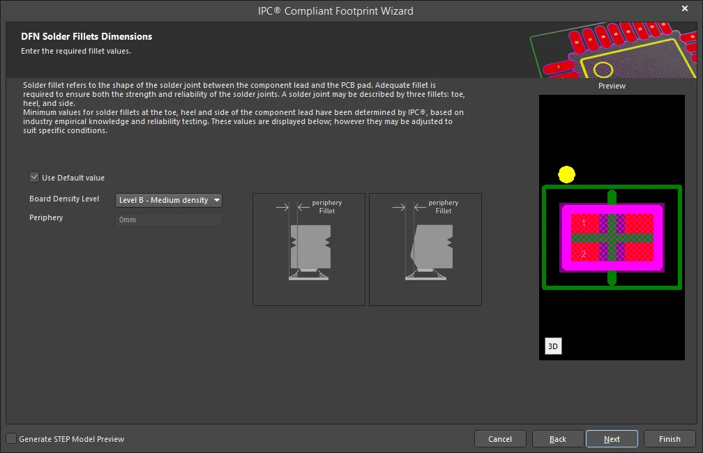
Set the required solder fillet values on the DFN Solder Fillets Dimensions page. Solder fillet refers to the shape of the solder joint between the component lead and the PCB pad. Adequate fillet is required to ensure both the strength and reliability of the solder joints. A solder joint may be described by three fillets: toe, heel, and side.
Minimum values for solder fillets at the toe, heel and side of the component lead have been determined by IPC based on industry empirical knowledge and reliability testing. Enable Use Default value to use the values displayed or you can adjust it to suit your specific needs.
Use the Board Density Level drop-down to select the desired board density. Choose from Level A - Low density, Level B - Medium density, and Level C - High density. Enter the Periphery value in the textbox.
DFN Tolerance Dimensions
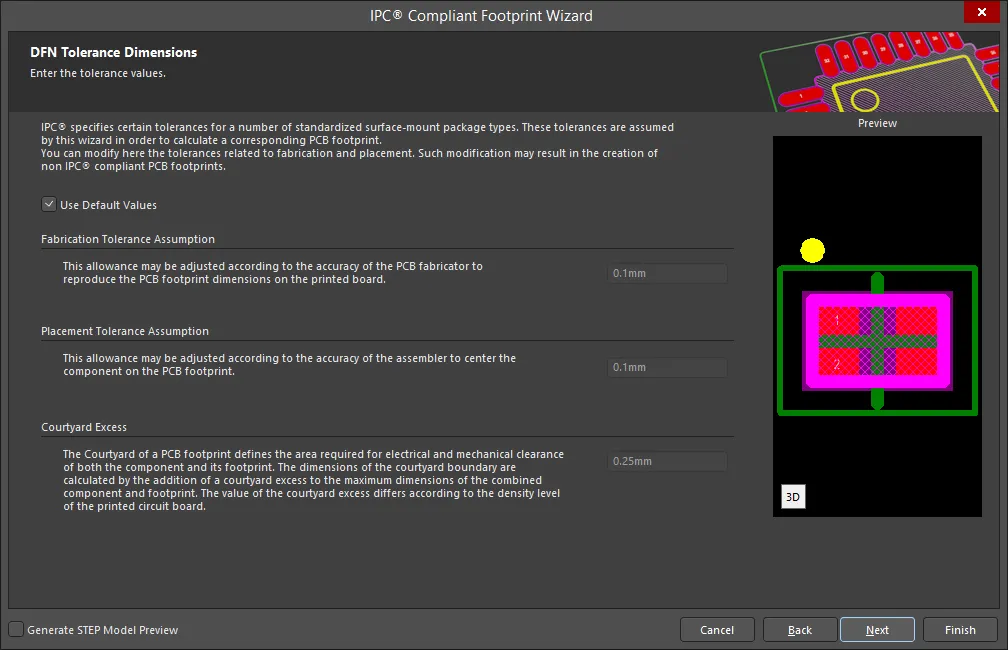
IPC specifies certain tolerances for a number of standardized surface-mount package types. These tolerances are assumed by the Wizard in order to calculate a corresponding PCB footprint. You can modify the tolerances related to fabrication and placement on the DFN Tolerance Dimensions page. Enable Use Default Values to accept the displayed values. You can change the values for Fabrication Tolerance Assumption, Placement Tolerance Assumption, and Courtyard Excess by entering the new values directly in the textboxes.
Modifying the IPC Tolerances may result in PCB footprints that are not IPC compliant.
DFN Footprint Dimensions
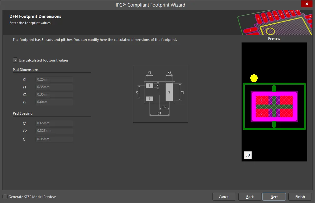
The DFN Footprint Dimensions page displays the inferred footprint dimensions using the package dimensions previously defined. To use the displayed values, enable Use calculated footprint values or enter new values for Pad Dimensions and Pad Spacing.
DFN Silkscreen Dimensions
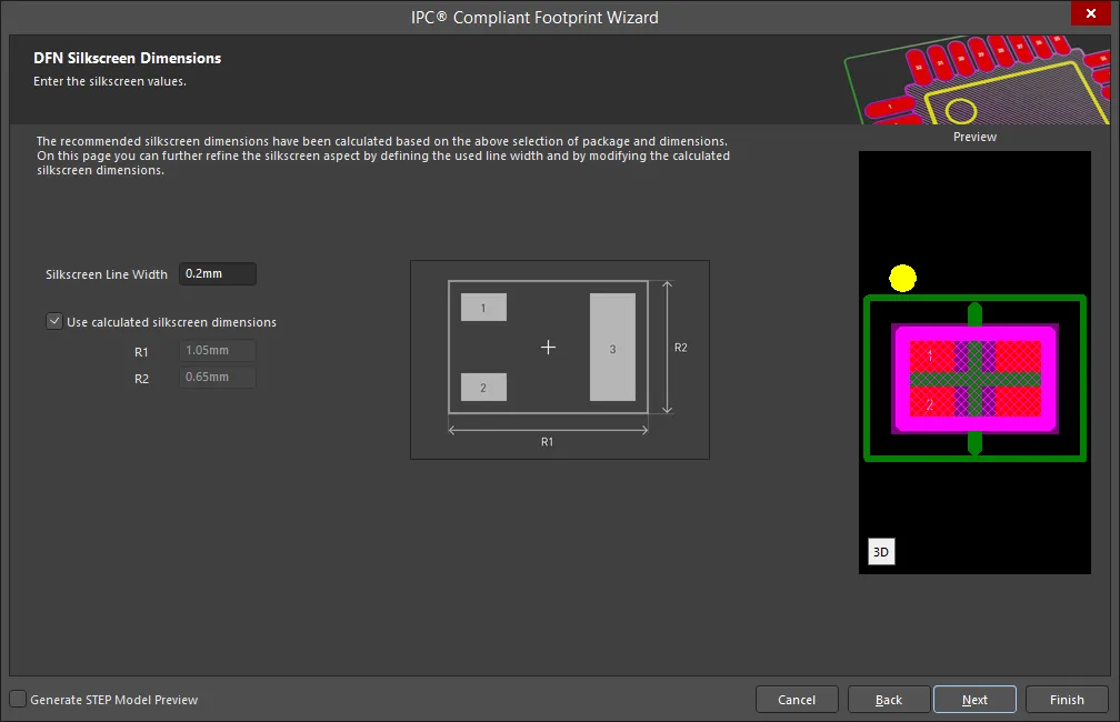
The DFN Silkscreen Dimensions page displays the inferred silkscreen dimensions using the package dimensions previously defined. You can further define the silkscreen dimensions by entering a new value for the Silkscreen Line Width. Enable Use calculated silkscreen dimensions to use the values displayed or disable the option and enter the desired values.
DFN Mechanical Dimensions

The DFN Mechanical Dimensions page displays the inferred mechanical dimensions using the package dimensions previously defined.
Enable Add Courtyard Information and Add Assembly Information to add courtyard and assembly information to the component drawing. For each, you can use the IPC calculated dimensions or enter new values directly in the textboxes. If desired, enter a new Line Width directly in the textbox. You can also select the mechanical layer for courtyard and assembly by using the drop-down next to Layer and selecting the desired mechanical layer.
A component body contains the volumetric information corresponding to the package dimensions. Enable Add Component Body Information to include this information. Enable Use calculated values to use the values displayed or disable the option and enter new desired values. You can also select the mechanical layer for the component body by using the drop-down next to Layer and selecting the desired mechanical layer.
CHIP
Copy Link
Copied
CHIP
Chip Component Package Dimensions
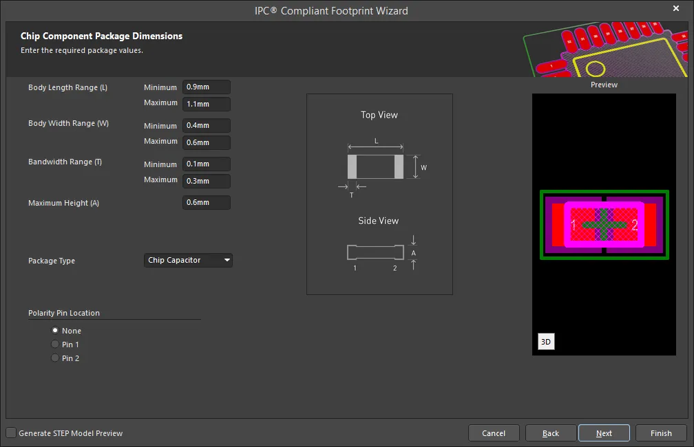
Enter the required values for the package dimensions on the Chip Component Package Dimensions page.
Enter the Body Length Range, Body Width Range, Bandwidth Range, and Maximum Height. Use the drop-down to select the package type: Chip Capacitor, Chip Inductor, Chip Resistor, or Chip Diode.
Select the Polarity Pin Location. Choices include: None, Pin 1, and Pin 2.
Chip Component Package Heel Spacing
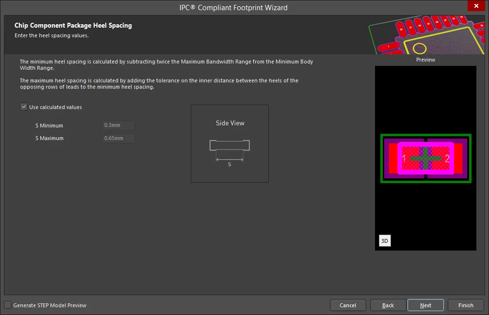
Set the desired heel spacing values on the Chip Component Package Heel Spacing page.
Enable the Use calculated values checkbox to use the values currently displayed or enter new values directly in the textboxes for S Minimum and S Maximum.
Chip Component Solder Fillets

Set the required solder fillet values on the Chip Component Solder Fillets page. Solder fillet refers to the shape of the solder joint between the component lead and the PCB pad. Adequate fillet is required to ensure both the strength and reliability of the solder joints. A solder joint may be described by three fillets: toe, heel, and side.
Minimum values for solder fillets at the toe, heel and side of the component lead have been determined by IPC based on industry empirical knowledge and reliability testing. Enable Use default values to use the values displayed or you can adjust them to suit your specific needs.
Use the Board density Level drop-down to select the desired board density. Choose from Level A - Low density, Level B - Medium density, and Level C - High density. The Preview region is dynamically updated to show your changes.
To update the values for Toe Fillet (JT Min), Heel Fillet (JH Min), and Side Fillet (JS Min), the Use default values option must be disabled. Enter the new values directly in the textboxes.
Chip Component Component Tolerances
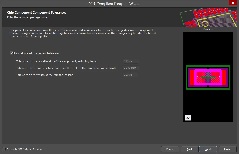
Enter the required values for component tolerances on the Chip Component Component Tolerances page.
Component manufacturers usually specify the minimum and maximum value for each package dimension. Component tolerance ranges are derived by subtracting the minimum value from the maximum value. You can adjust three of these ranges.
If the displayed values are correct for your current situation, enable the Use calculated component tolerances textbox. If the tolerance values need to be adjusted, ensure Use calculated component tolerances is disabled then enter the new values directly in the textboxes next to Tolerance on the overall width of the component, including leads, Tolerance on the inner distance between the heels of the opposing rows of leads, and Tolerance on the width of the component leads.
Chip Component IPC Tolerances
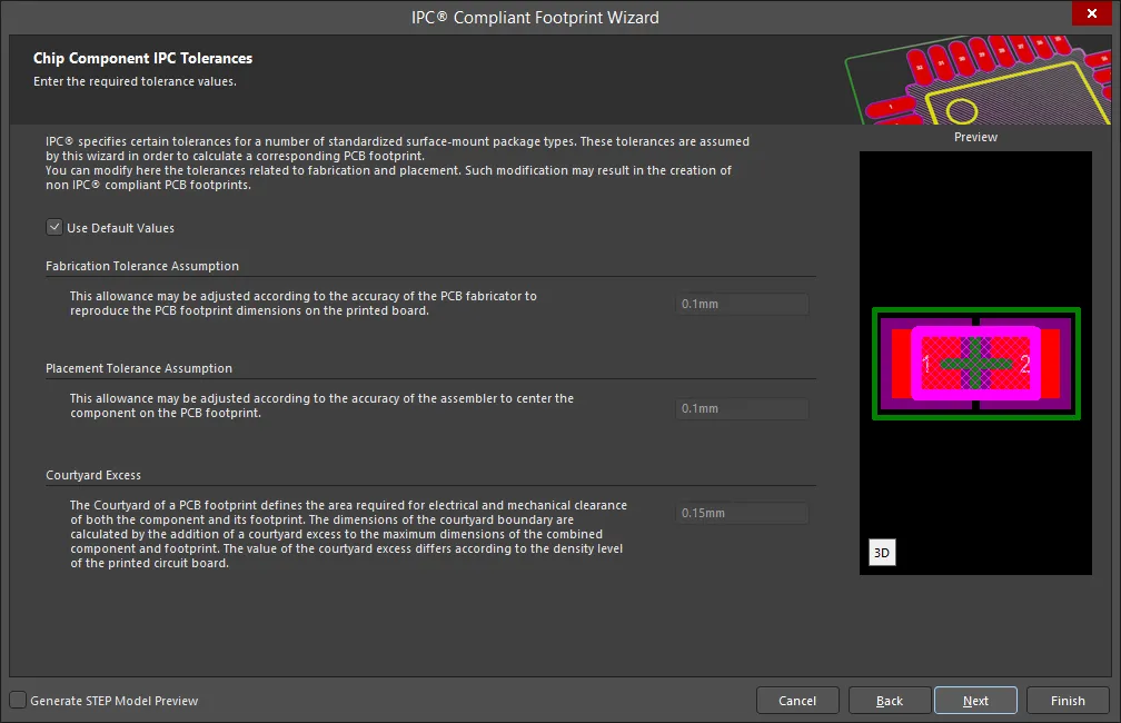
IPC specifies certain tolerances for a number of standardized surface-mount package types. These tolerances are assumed by the Wizard in order to calculate a corresponding PCB footprint. You can modify the tolerances related to fabrication and placement on the Chip Component IPC Tolerances page. Enable Use Default Values to accept the displayed values. You can change the values for Fabrication Tolerance Assumption, Placement Tolerance Assumption, and Courtyard Excess by entering the new values directly in the textboxes.
Modifying the IPC Tolerances may result in PCB footprints that are not IPC compliant.
Chip Component Footprint Dimensions
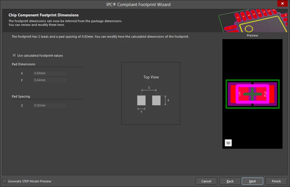
The Chip Component Footprint Dimensions page displays the inferred footprint dimensions using the package dimensions previously defined. To use the displayed values, enable Use calculated footprint values or enter new values for Pad Dimensions and Pad Spacing.
Chip Component Silkscreen Dimensions
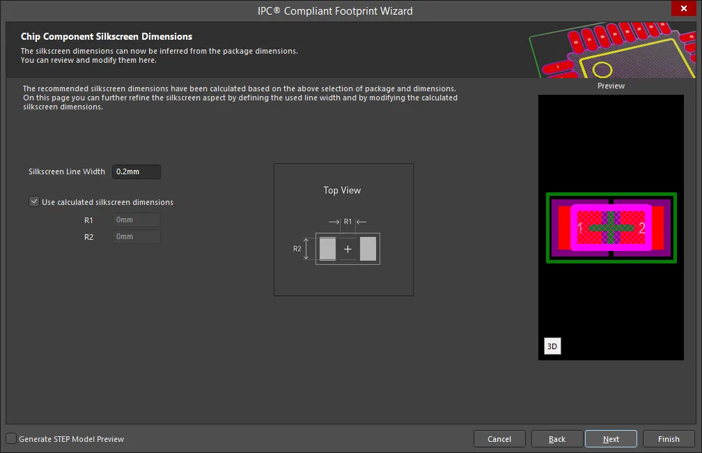
The Chip Component Silkscreen Dimensions page displays the inferred silkscreen dimensions using the package dimensions previously defined. You can further define the silkscreen dimensions by entering a new value for the Silkscreen Line Width. Enable Use calculated silkscreen dimensions to use the values displayed or disable the option and enter the desired values.
Chip Component Courtyard, Assembly and Component Body Information
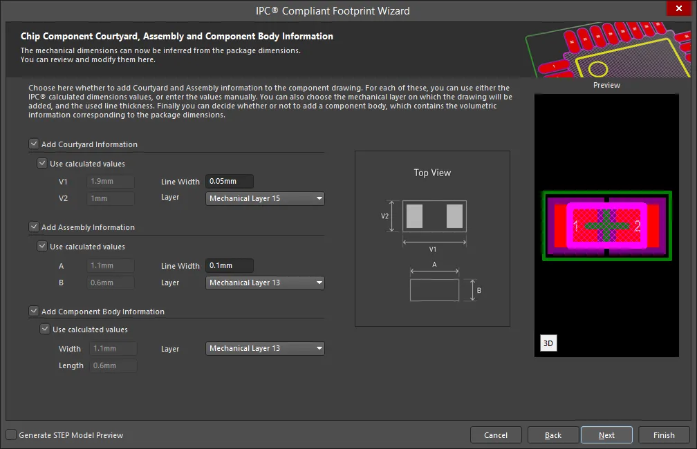
The Chip Component Courtyard, Assembly and Component Body Information page displays the inferred mechanical dimensions using the package dimensions previously defined.
Enable Add Courtyard Information and Add Assembly Information to add courtyard and assembly information to the component drawing. For each, you can use the IPC calculated dimensions or enter new values directly in the textboxes. If desired, enter a new Line Width directly in the textbox. You can also select the mechanical layer for courtyard and assembly by using the drop-down next to Layer and selecting the desired mechanical layer.
A component body contains the volumetric information corresponding to the package dimensions. Enable Add Component Body Information to include this information. Enable Use calculated values to use the values displayed or disable the option and enter new desired values. You can also select the mechanical layer for the component body by using the drop-down next to Layer and selecting the desired mechanical layer.
CQFP
Copy Link
Copied
CQFP
CQFP Package Overall Dimensions
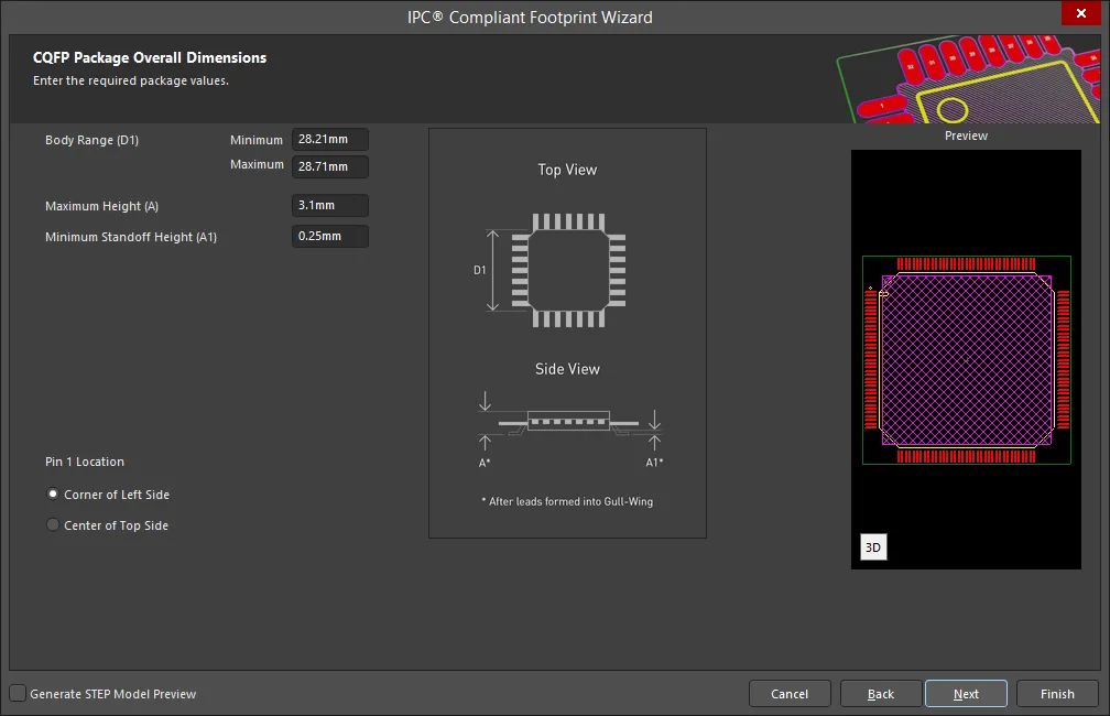
Use the CQFP Package Overall Dimensions page to set the package values.
Enter the Body Range, Maximum Height, and Minimum Standoff Height.
Select either Corner of Left Side or Center of Top Side for the Pin 1 Location.
CQFP Package Pin Dimensions
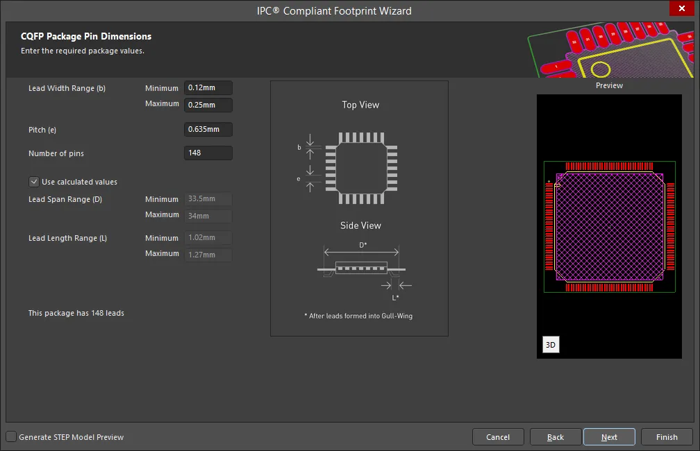
Enter the required values for the package pin dimensions on the CQFP Package Pin Dimensions page.
Enter the Lead Width Range(s), Pitch, and Number of pins.
Enable Use calculated values to use the values displayed or disable the option and enter the desired values for Lead Span Range(s) and Lead Length Range(s).
CQFP Package Heel Spacing

Set the desired heel spacing values on the CQFP Package Heel Spacing page.
Enable the Use calculated values checkbox to use the values currently displayed or enter new values directly in the textboxes for S Minimum and S Maximum.
CQFP Solder Fillets
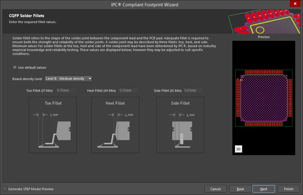
Set the required solder fillet values on the CQFP Solder Fillets page. Solder fillet refers to the shape of the solder joint between the component lead and the PCB pad. Adequate fillet is required to ensure both the strength and reliability of the solder joints. A solder joint may be described by three fillets: toe, heel, and side.
Minimum values for solder fillets at the toe, heel and side of the component lead have been determined by IPC based on industry empirical knowledge and reliability testing. Enable Use default values to use the values displayed or you can adjust them to suit your specific needs.
Use the Board density Level drop-down to select the desired board density. Choose from Level A - Low density, Level B - Medium density, and Level C - High density. The Preview region is dynamically updated to show your changes.
To update the values for Toe Fillet (JT Min), Heel Fillet (JH Min), and Side Fillet (JS Min), the Use default values option must be disabled. Enter the new values directly in the textboxes.
CQFP Component Tolerances

Enter the required values for component tolerances on the CQFP Component Tolerances page.
Component manufacturers usually specify the minimum and maximum value for each package dimension. Component tolerance ranges are derived by subtracting the minimum value from the maximum value. You can adjust three of these ranges.
If the displayed values are correct for your current situation, enable the Use calculated component tolerances textbox. If the tolerance values need to be adjusted, ensure Use calculated component tolerances is disabled then enter the new values directly in the textboxes next to Tolerance on the overall width of the component, including leads, Tolerance on the inner distance between the heels of the opposing rows of leads, and Tolerance on the width of the component leads.
CQFP IPC Tolerances
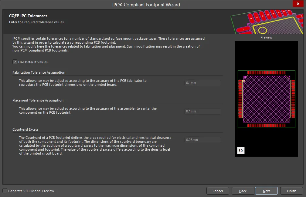
IPC specifies certain tolerances for a number of standardized surface-mount package types. These tolerances are assumed by the Wizard in order to calculate a corresponding PCB footprint. You can modify the tolerances related to fabrication and placement on the CQFP IPC Tolerances page. Enable Use Default Values to accept the displayed values. You can change the values for Fabrication Tolerance Assumption, Placement Tolerance Assumption, and Courtyard Excess by entering the new values directly in the textboxes.
Modifying the IPC Tolerances may result in PCB footprints that are not IPC compliant.
CQFP Footprint Dimensions
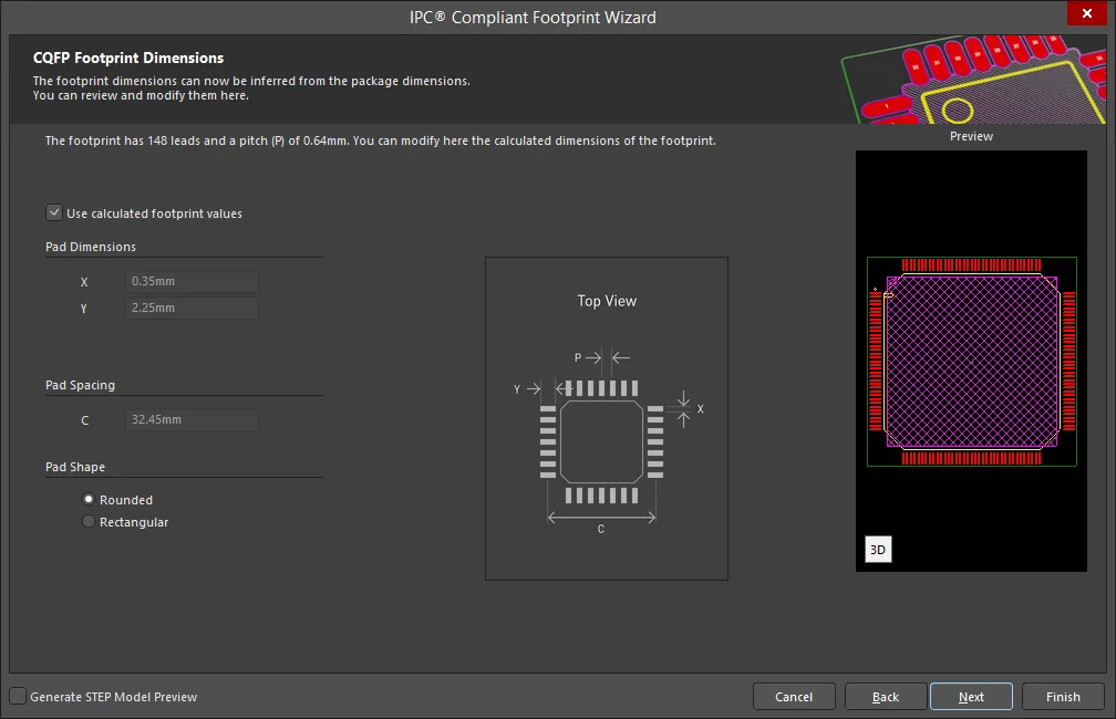
The CQFP Footprint Dimensions page displays the inferred footprint dimensions using the package dimensions previously defined. To use the displayed values, enable Use calculated footprint values or enter new values for Pad Dimensions and Pad Spacing.
Select either Rounded or Rectangular for Pad Shape.
CQFP Silkscreen Dimensions

The CQFP Silkscreen Dimensions page displays the inferred silkscreen dimensions using the package dimensions previously defined. You can further define the silkscreen dimensions by entering a new value for the Silkscreen Line Width. Enable Use calculated silkscreen dimensions to use the values displayed or disable the option and enter the desired values.
CQFP Courtyard, Assembly and Component Body Information

The CQFP Courtyard, Assembly and Component Body Information page displays the inferred mechanical dimensions using the package dimensions previously defined.
Enable Add Courtyard Information and Add Assembly Information to add courtyard and assembly information to the component drawing. For each, you can use the IPC calculated dimensions or enter new values directly in the textboxes. If desired, enter a new Line Width directly in the textbox. You can also select the mechanical layer for courtyard and assembly by using the drop-down next to Layer and selecting the desired mechanical layer.
A component body contains the volumetric information corresponding to the package dimensions. Enable Add Component Body Information to include this information. Enable Use calculated values to use the values displayed or disable the option and enter new desired values. You can also select the mechanical layer for the component body by using the drop-down next to Layer and selecting the desired mechanical layer.
DPAK
Copy Link
Copied
DPAK
DPAK Package Overall Dimensions
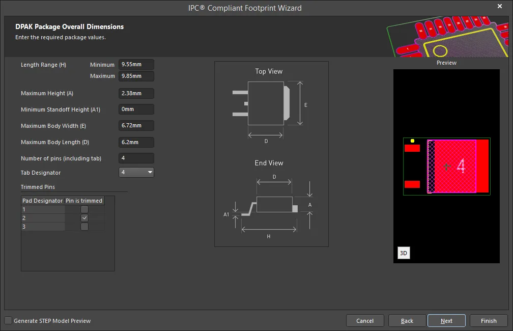
Use the DPAK Package Overall Dimensions page to set the package values.
Enter the Length Range, Maximum Height, Minimum Standoff Height, Maximum Body Width, Maximum Body Length, and Number of pins (including tab).
Use the drop-down to select the Tab Designator.
Enable the Pin is trimmed checkbox to denote trimmed pins for each pad designator in the table.
DPAK Package Pin Dimensions
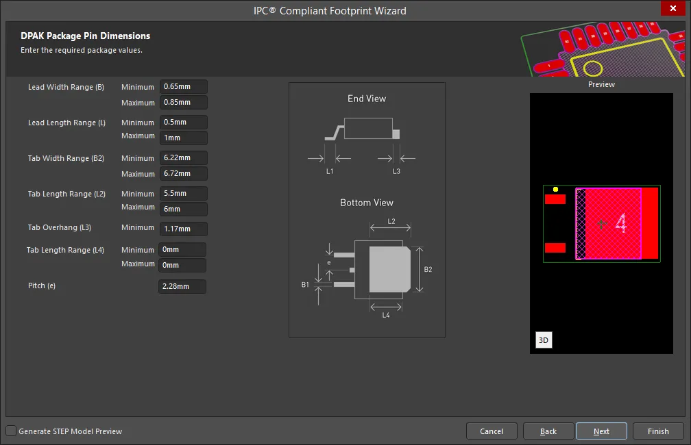
Enter the required values for the package pin dimensions on the DPAK Package Pin Dimensions page.
Enter the Lead Width Range(s), Lead Length Range(s), Tab Width Range(s), Tab Length Range(s), Tab Overhang, and Pitch(es).
DPAK Package Heel Spacing
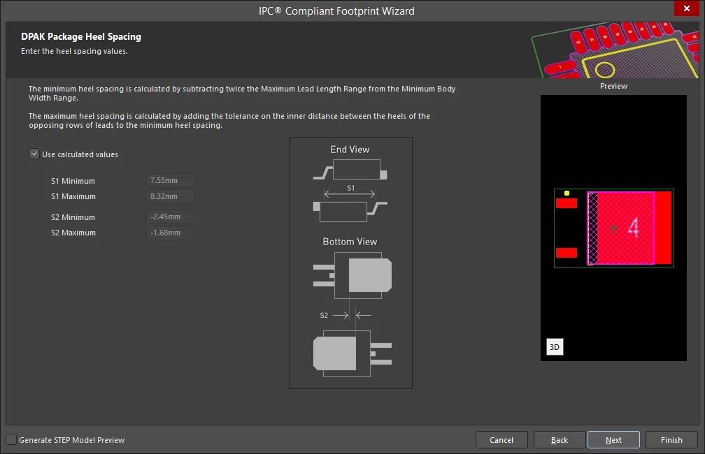
Set the desired heel spacing values on the DPAK Package Heel Spacing page.
Enable the Use calculated values checkbox to use the values currently displayed or enter new values directly in the textboxes for S Minimum and S Maximum.
DPAK Solder Fillets
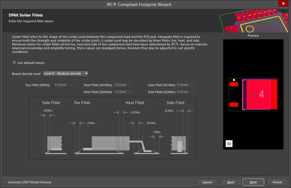
Set the required solder fillet values on the DPAK Solder Fillets page. Solder fillet refers to the shape of the solder joint between the component lead and the PCB pad. Adequate fillet is required to ensure both the strength and reliability of the solder joints. A solder joint may be described by three fillets: toe, heel, and side.
Minimum values for solder fillets at the toe, heel and side of the component lead have been determined by IPC based on industry empirical knowledge and reliability testing. Enable Use default values to use the values displayed or you can adjust them to suit your specific needs.
Use the Board density Level drop-down to select the desired board density. Choose from Level A - Low density, Level B - Medium density, and Level C - High density. The Preview region is dynamically updated to show your changes.
To update the values for Toe Fillet (JT Min), Heel Fillet(s), and Side Fillet(s), the Use default values option must be disabled. Enter the new values directly in the textboxes.
DPAK Component Tolerances

Enter the required values for component tolerances on the DPAK Component Tolerances page.
Component manufacturers usually specify the minimum and maximum value for each package dimension. Component tolerance ranges are derived by subtracting the minimum value from the maximum value. You can adjust three of these ranges.
If the displayed values are correct for your current situation, enable the Use calculated component tolerances textbox. If the tolerance values need to be adjusted, ensure Use calculated component tolerances is disabled then enter the new values directly in the textboxes next to Tolerance on the overall width of the component, including leads, Tolerance on the inner distance between the heels of the opposing rows of leads, and Tolerance on the width of the component leads.
DPAK IPC Tolerances
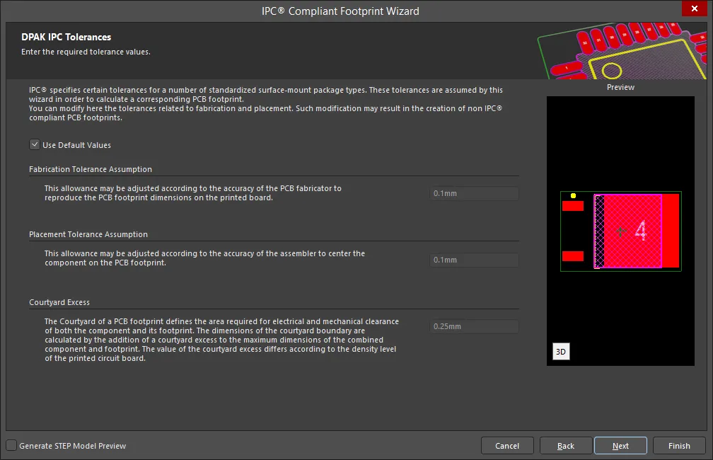
IPC specifies certain tolerances for a number of standardized surface-mount package types. These tolerances are assumed by the Wizard in order to calculate a corresponding PCB footprint. You can modify the tolerances related to fabrication and placement on the DPAK IPC Tolerances page. Enable Use Default Values to accept the displayed values. You can change the values for Fabrication Tolerance Assumption, Placement Tolerance Assumption, and Courtyard Excess by entering the new values directly in the textboxes.
Modifying the IPC Tolerances may result in PCB footprints that are not IPC compliant.
DPAK Footprint Dimensions
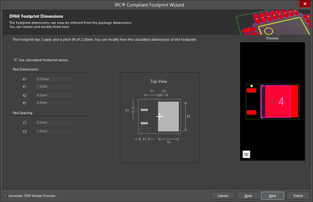
The DPAK Footprint Dimensions page displays the inferred footprint dimensions using the package dimensions previously defined. To use the displayed values, enable Use calculated footprint values or enter new values for Pad Dimensions and Pad Spacing.
DPAK Silkscreen Dimensions
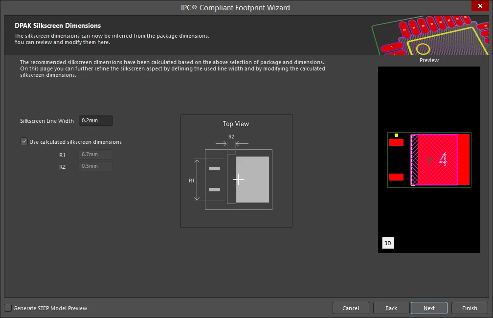
The DPAK Silkscreen Dimensions page displays the inferred silkscreen dimensions using the package dimensions previously defined. You can further define the silkscreen dimensions by entering a new value for the Silkscreen Line Width. Enable Use calculated silkscreen dimensions to use the values displayed or disable the option and enter the desired values.
DPAK Courtyard, Assembly and Component Body Information
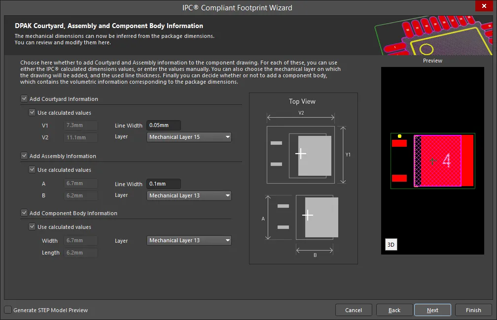
The DPAK Courtyard, Assembly and Component Body Information page displays the inferred mechanical dimensions using the package dimensions previously defined.
Enable Add Courtyard Information and Add Assembly Information to add courtyard and assembly information to the component drawing. For each, you can use the IPC calculated dimensions or enter new values directly in the textboxes. If desired, enter a new Line Width directly in the textbox. You can also select the mechanical layer for courtyard and assembly by using the drop-down next to Layer and selecting the desired mechanical layer.
A component body contains the volumetric information corresponding to the package dimensions. Enable Add Component Body Information to include this information. Enable Use calculated values to use the values displayed or disable the option and enter new desired values. You can also select the mechanical layer for the component body by using the drop-down next to Layer and selecting the desired mechanical layer.
LCC
Copy Link
Copied
LCC
Leadless Chip Carrier Package Dimensions

Use the Leadless Chip Carrier Package Dimensions page to enter the required package values for Body Width Range, Body Length Range, Maximum Height, and Minimum Package Height. Set the Pin 1 Location by selecting either Side of D or Center of E.
Leadless Chip Carrier Package Pin Dimensions

Enter the required values for the package pin dimensions on the Leadless Chip Carrier Package Pin Dimensions page.
Leadless Chip Carrier Package Toe Spacing
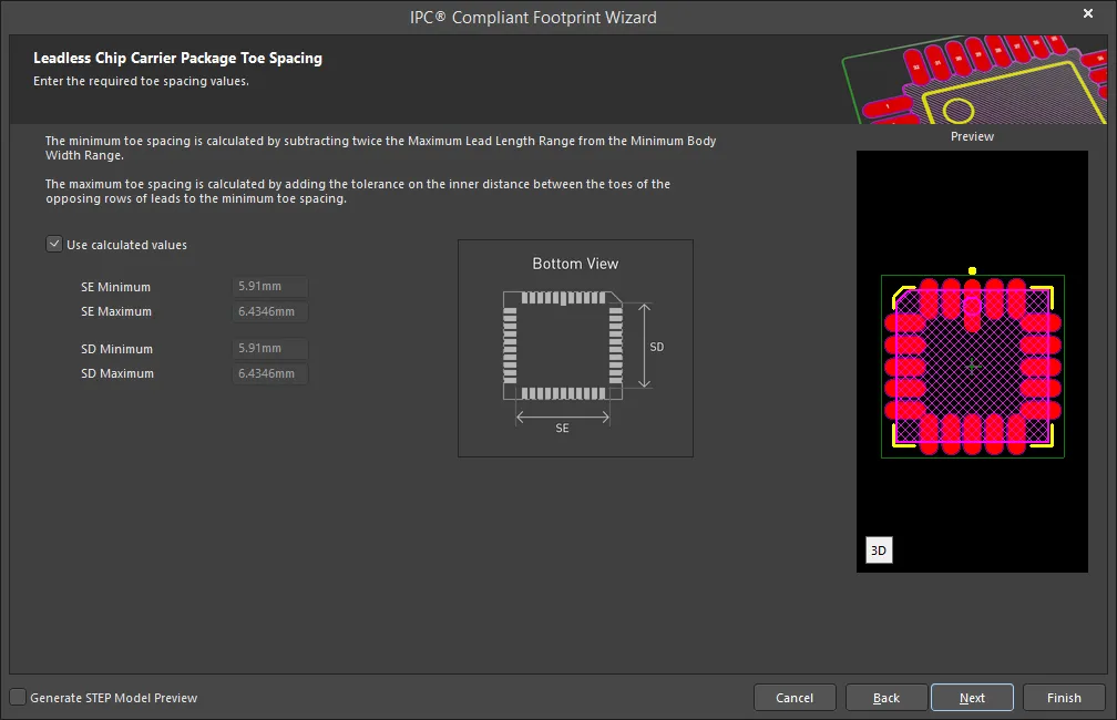
Use the Leadless Chip Carrier Package Toe Spacing page to enter the required toe spacing values. Enable Use calculated values to accept the displayed values or disable the checkbox and enter the desired values.
Leadless Chip Carrier Solder Fillets

Set the required solder fillet values on the Leadless Chip Carrier Solder Fillets page. Solder fillet refers to the shape of the solder joint between the component lead and the PCB pad. Adequate fillet is required to ensure both the strength and reliability of the solder joints. A solder joint may be described by three fillets: toe, heel, and side.
Minimum values for solder fillets at the toe, heel and side of the component lead have been determined by IPC based on industry empirical knowledge and reliability testing. Enable Use default values to use the values displayed or you can adjust them to suit your specific needs.
Use the Board density Level drop-down to select the desired board density. Choose from Level A - Low density, Level B - Medium density, and Level C - High density. The Preview region is dynamically updated to show your changes.
To update the values for Heel Fillet (JH Min), Toe Fillet (JT Min), and Side Fillet (JS Min), the Use default values option must be disabled. Enter the new values directly in the textboxes.
Leadless Chip Carrier Component Tolerances
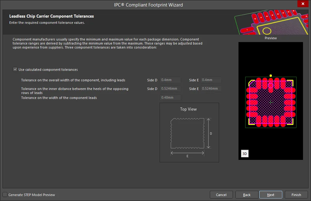
Enter the required values for component tolerances on the Leadless Chip Carrier Component Tolerances page.
Component manufacturers usually specify the minimum and maximum value for each package dimension. Component tolerance ranges are derived by subtracting the minimum value from the maximum value. You can adjust three of these ranges.
If the displayed values are correct for your current situation, enable the Use calculated component tolerances textbox. If the tolerance values need to be adjusted, ensure Use calculated component tolerances is disabled then enter the new values directly in the textboxes next to Tolerance on the overall width of the component, including leads, Tolerance on the inner distance between the heels of the opposing rows of leads, and Tolerance on the width of the component leads.
Leadless Chip Carrier IPC Tolerances

IPC specifies certain tolerances for a number of standardized surface-mount package types. These tolerances are assumed by the Wizard in order to calculate a corresponding PCB footprint. You can modify the tolerances related to fabrication and placement on the Leadless Chip Carrier IPC Tolerances page. Enable Use Default Values to accept the displayed values. You can change the values for Fabrication Tolerance Assumption, Placement Tolerance Assumption, and Courtyard Excess by entering the new values directly in the textboxes.
Modifying the IPC Tolerances may result in PCB footprints that are not IPC compliant.
Leadless Chip Carrier Footprint Dimensions
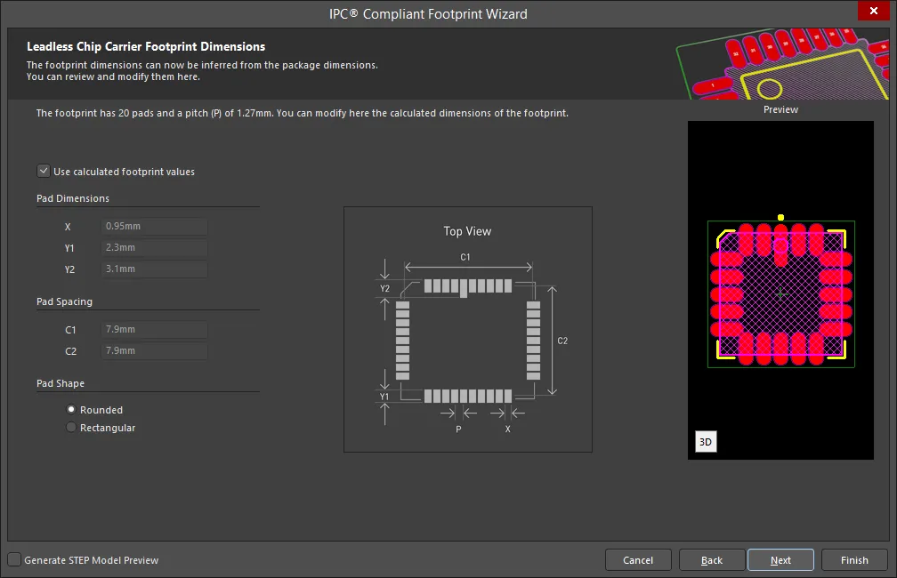
The Leadless Chip Carrier Footprint Dimensions page displays the inferred footprint dimensions using the package dimensions previously defined. To use the displayed values, enable Use calculated footprint values or enter new values for Pad Dimensions and Pad Spacing.
Select either Rounded or Rectangular for Pad Shape.
Leadless Chip Carrier Silkscreen Dimensions
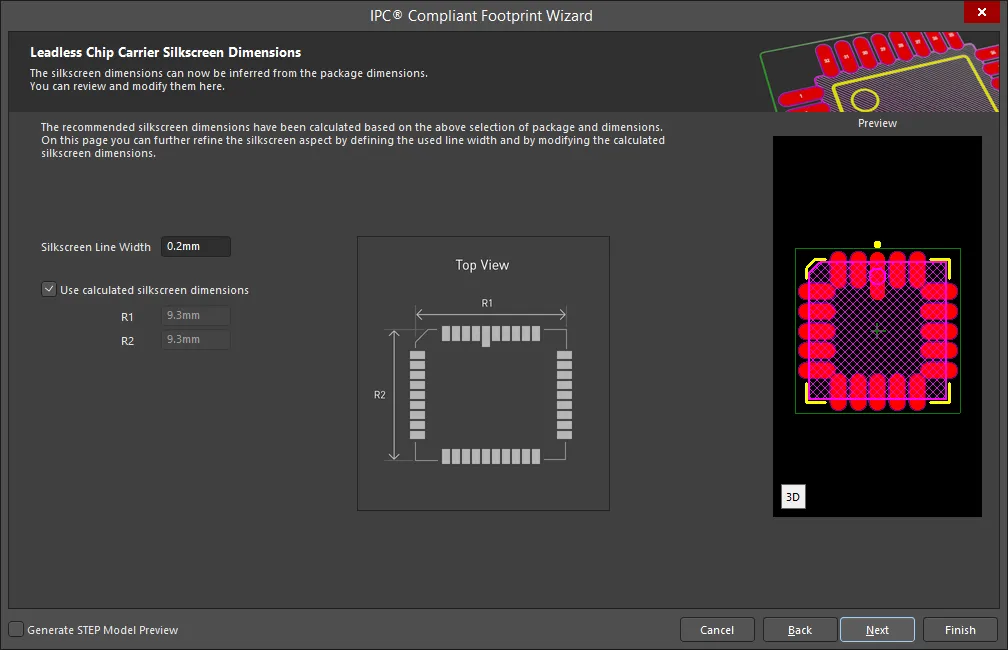
The Leadless Chip Carrier Silkscreen Dimensions page displays the inferred silkscreen dimensions using the package dimensions previously defined. You can further define the silkscreen dimensions by entering a new value for the Silkscreen Line Width. Enable Use calculated silkscreen dimensions to use the values displayed or disable the option and enter the desired values.
Leadless Chip Carrier Courtyard, Assembly and Component Body Information
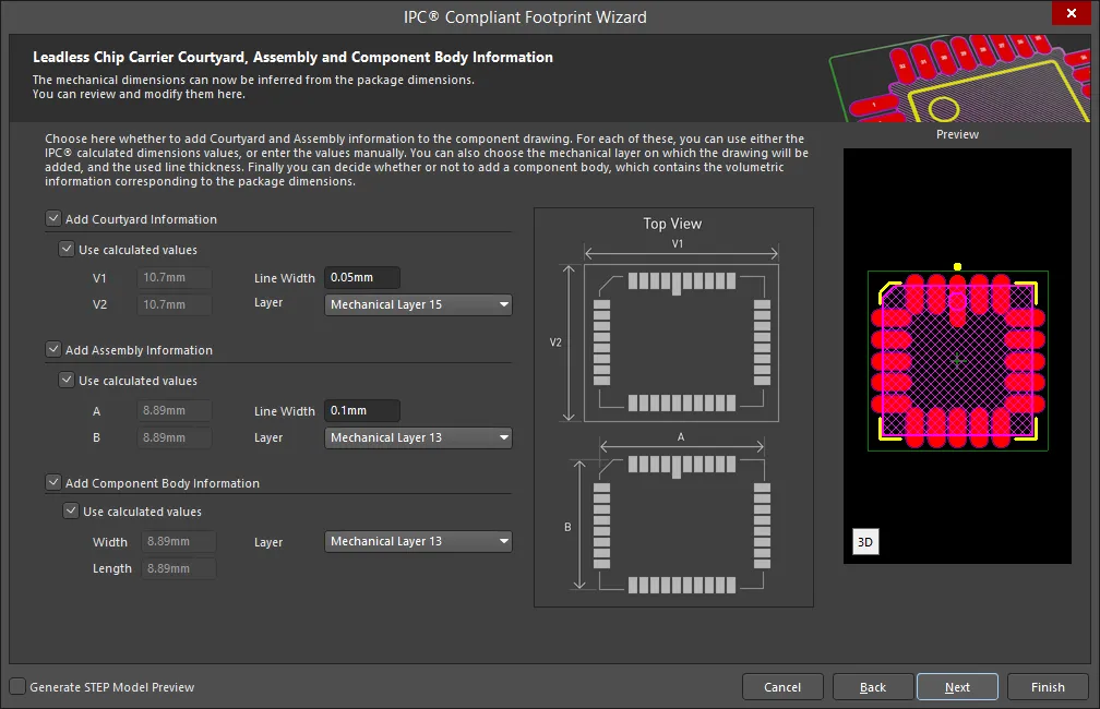
The Leadless Chip Carrier Courtyard, Assembly and Component Body Information page displays the inferred mechanical dimensions using the package dimensions previously defined.
Enable Add Courtyard Information and Add Assembly Information to add courtyard and assembly information to the component drawing. For each, you can use the IPC calculated dimensions or enter new values directly in the textboxes. If desired, enter a new Line Width directly in the textbox. You can also select the mechanical layer for courtyard and assembly by using the drop-down next to Layer and selecting the desired mechanical layer.
A component body contains the volumetric information corresponding to the package dimensions. Enable Add Component Body Information to include this information. Enable Use calculated values to use the values displayed or disable the option and enter new desired values. You can also select the mechanical layer for the component body by using the drop-down next to Layer and selecting the desired mechanical layer.
LGA
Copy Link
Copied
LGA
LGA Package Dimensions
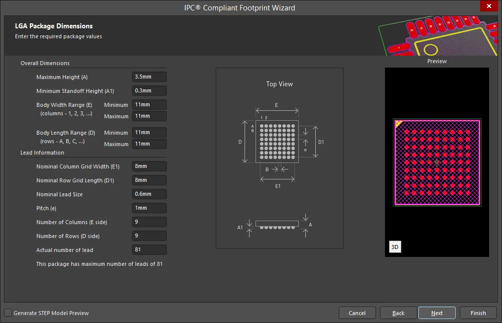
Use the LGA Package Dimensions page to enter the required package values for Overall Dimensions and Lead Information.
LGA Package Layout Options
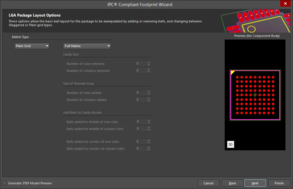
Use the LGA Package Layout Options page to define the basic ball layout by adding or removing balls and changing the grid type.
The Add Balls to Cavity Border selections are only accessible if Selectively Depopulated is selected from the drop-down.
Select the grid type from the drop-down. Selections include Plain Grid or Staggered Grid.
Select the matrix type from the drop-down. Selections include Full Matrix, Perimeter, Thermally Enhanced, and Selectively Depopulated.
- If Full Matrix is selected, none of the other options of the region are available.
- If Perimeter is selected, only Cavity Size is accessible for updating.
- If Thermally Enhanced is selected, only Cavity Size and Size of Thermal Array are accessible for updating.
- If Selectively Depopulated is selected, all areas, including Add Balls to Cavity Border, are accessible for updating.
LGA Pads Diameter
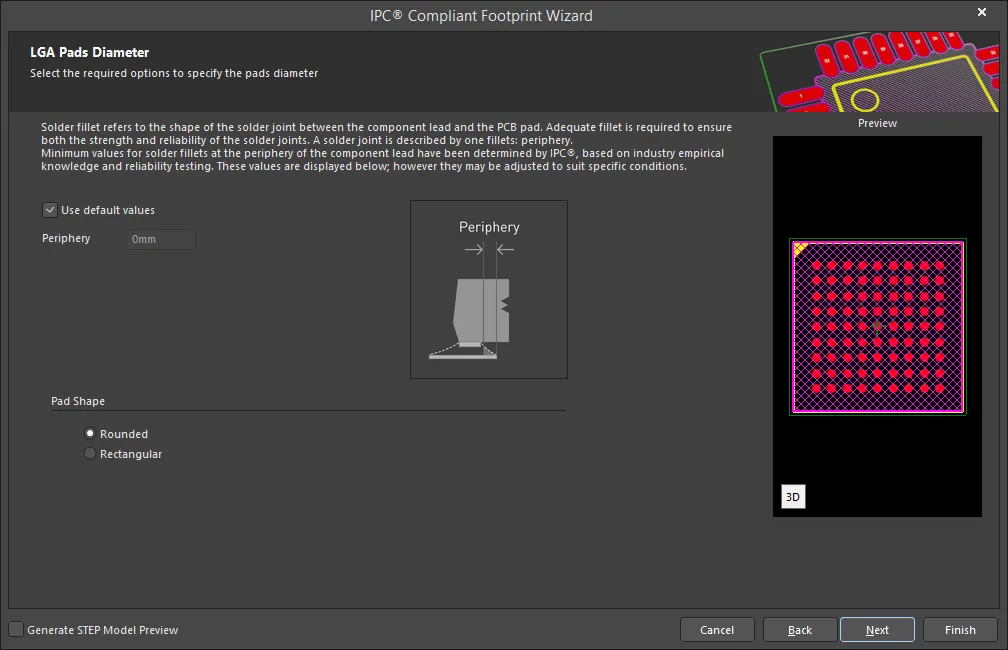
The LGA Pads Diameter page is used to specify the pad diameter of the footprint. Enable Use default values to accept the displayed Periphery value or disable and enter new values.
Select either Rounded or Rectangular for Pad Shape.
LGA Silkscreen Dimensions

The LGA Silkscreen Dimensions page displays the inferred silkscreen dimensions using the package dimensions previously defined. You can further define the silkscreen dimensions by entering a new value for the Silkscreen Line Width. Enable Use calculated silkscreen dimensions to use the values displayed or disable the option and enter the desired values.
LGA Courtyard, Assembly and Component Body Information
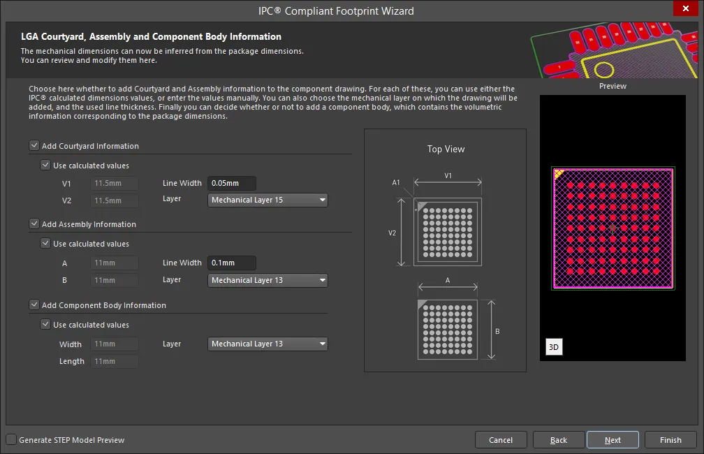
The LGA Courtyard, Assembly and Component Body Information page displays the inferred mechanical dimensions using the package dimensions previously defined.
Enable Add Courtyard Information and Add Assembly Information to add courtyard and assembly information to the component drawing. For each, you can use the IPC calculated dimensions or enter new values directly in the textboxes. If desired, enter a new Line Width directly in the textbox. You can also select the mechanical layer for courtyard and assembly by using the drop-down next to Layer and selecting the desired mechanical layer.
A component body contains the volumetric information corresponding to the package dimensions. Enable Add Component Body Information to include this information. Enable Use calculated values to use the values displayed or disable the option and enter new desired values. You can also select the mechanical layer for the component body by using the drop-down next to Layer and selecting the desired mechanical layer.
MELF
Copy Link
Copied
MELF
MELF Component Package Dimensions
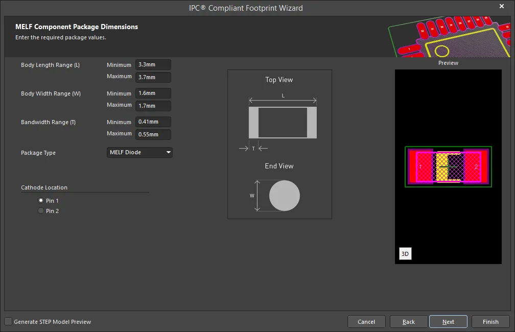
Use the MELF Component Package Dimensions page to enter the required package values for Body Length Range, Body Width Range, and Bandwidth Range. Use the drop-down to select the Package Type: MELF Diode or MELF Resistor. Set the Cathode Location by selecting either Pin 1 or Pin 2.
MELF Component Package Heel Spacing
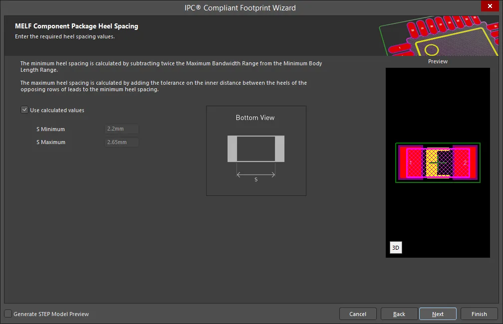
Set the desired heel spacing values on the MELF Component Package Heel Spacing page.
Enable the Use calculated values checkbox to use the values currently displayed or enter new values directly in the textboxes for S Minimum and S Maximum.
MELF Component Solder Fillets
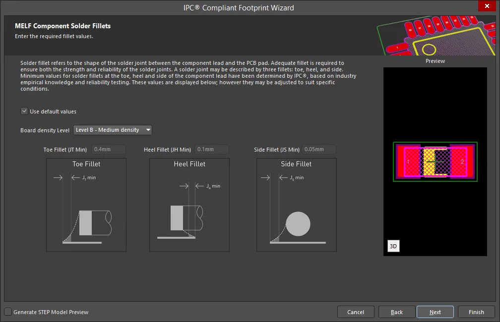
Set the required solder fillet values on the MELF Component Solder Fillets page. Solder fillet refers to the shape of the solder joint between the component lead and the PCB pad. Adequate fillet is required to ensure both the strength and reliability of the solder joints. A solder joint may be described by three fillets: toe, heel, and side.
Minimum values for solder fillets at the toe, heel and side of the component lead have been determined by IPC based on industry empirical knowledge and reliability testing. Enable Use default values to use the values displayed or you can adjust them to suit your specific needs.
Use the Board density Level drop-down to select the desired board density. Choose from Level A - Low density, Level B - Medium density, and Level C - High density. The Preview region is dynamically updated to show your changes.
To update the values for Toe Fillet (JT Min), Heel Fillet (JH Min), and Side Fillet (JS Min), the Use default values option must be disabled. Enter the new values directly in the textboxes.
MELF Component Component Tolerances
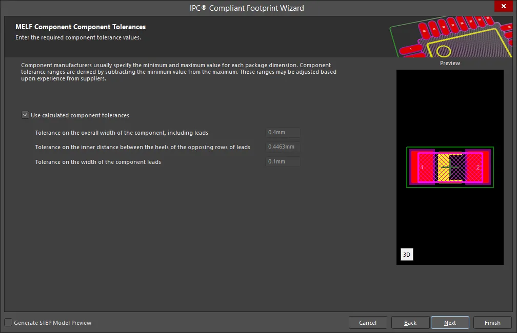
Enter the required values for component tolerances on the MELF Component Component Tolerances page.
Component manufacturers usually specify the minimum and maximum value for each package dimension. Component tolerance ranges are derived by subtracting the minimum value from the maximum value. You can adjust three of these ranges.
If the displayed values are correct for your current situation, enable the Use calculated component tolerances textbox. If the tolerance values need to be adjusted, ensure Use calculated component tolerances is disabled then enter the new values directly in the textboxes next to Tolerance on the overall width of the component, including leads, Tolerance on the inner distance between the heels of the opposing rows of leads, and Tolerance on the width of the component leads.
MELF Component IPC Tolerances
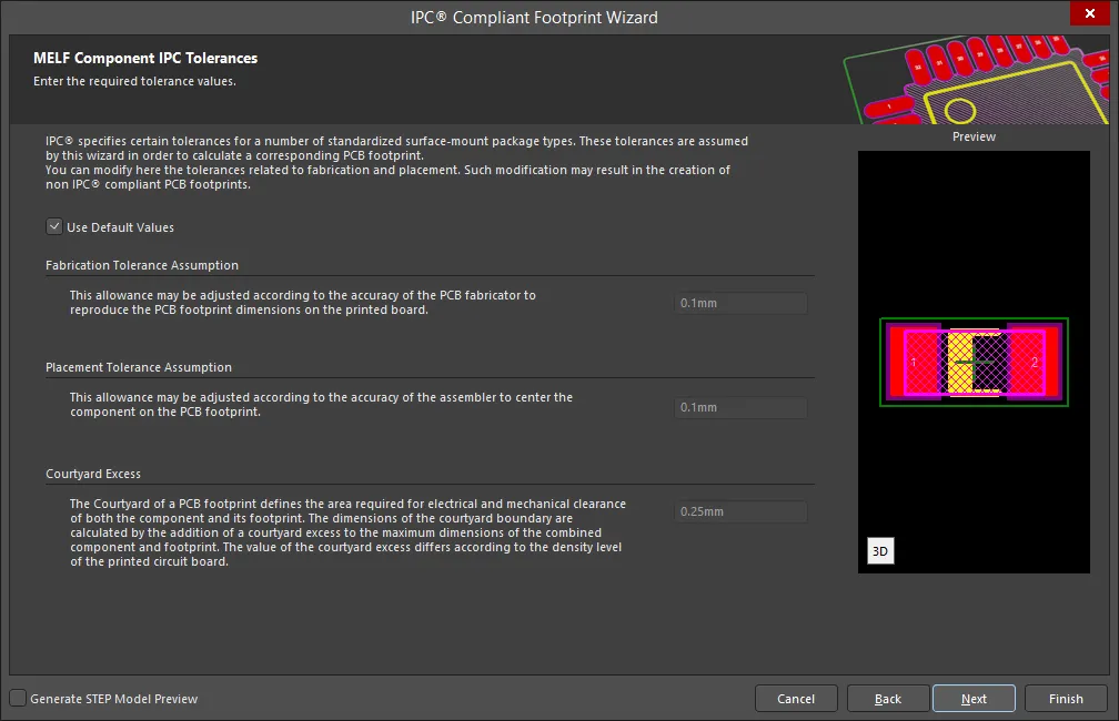
IPC specifies certain tolerances for a number of standardized surface-mount package types. These tolerances are assumed by the Wizard in order to calculate a corresponding PCB footprint. You can modify the tolerances related to fabrication and placement on the MELF Component IPC Tolerances page. Enable Use Default Values to accept the displayed values. You can change the values for Fabrication Tolerance Assumption, Placement Tolerance Assumption, and Courtyard Excess by entering the new values directly in the textboxes.
Modifying the IPC Tolerances may result in PCB footprints that are not IPC compliant.
MELF Component Footprint Dimensions
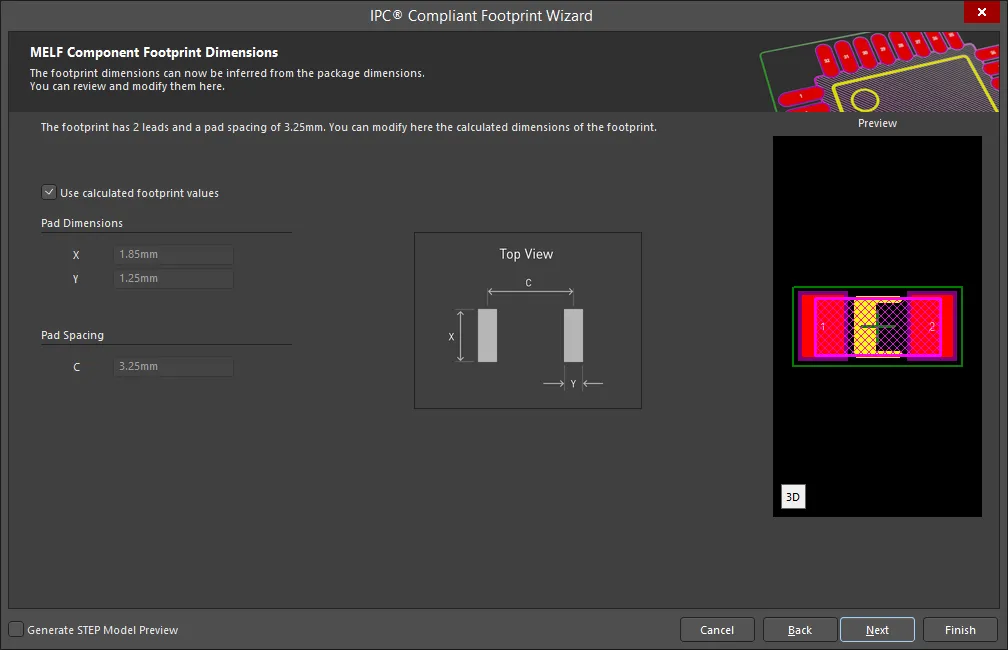
The MELF Component Footprint Dimensions page displays the inferred footprint dimensions using the package dimensions previously defined. To use the displayed values, enable Use calculated footprint values or enter new values for Pad Dimensions and Pad Spacing.
MELF Component Silkscreen Dimensions
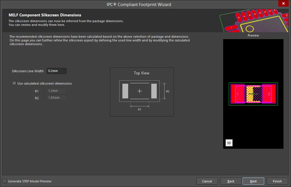
The MELF Component Silkscreen Dimensions page displays the inferred silkscreen dimensions using the package dimensions previously defined. You can further define the silkscreen dimensions by entering a new value for the Silkscreen Line Width. Enable Use calculated silkscreen dimensions to use the values displayed or disable the option and enter the desired values.
MELF Component Courtyard, Assembly and Component Body Information

The MELF Courtyard, Assembly and Component Body Information page displays the inferred mechanical dimensions using the package dimensions previously defined.
Enable Add Courtyard Information and Add Assembly Information to add courtyard and assembly information to the component drawing. For each, you can use the IPC calculated dimensions or enter new values directly in the textboxes. If desired, enter a new Line Width directly in the textbox. You can also select the mechanical layer for courtyard and assembly by using the drop-down next to Layer and selecting the desired mechanical layer.
A component body contains the volumetric information corresponding to the package dimensions. Enable Add Component Body Information to include this information. Enable Use calculated values to use the values displayed or disable the option and enter new desired values. You can also select the mechanical layer for the component body by using the drop-down next to Layer and selecting the desired mechanical layer.
MOLDED
Copy Link
Copied
MOLDED
Molded Component Package Dimensions
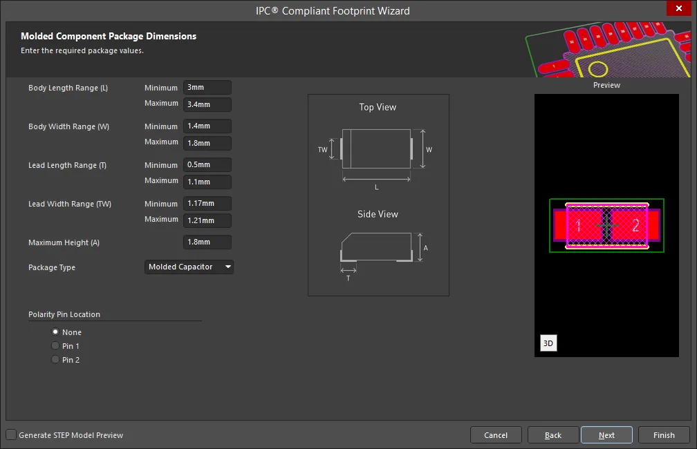
Use the Molded Component Package Dimensions page to enter the required package values for Body Length Range, Body Width Range, Lead Length Range, Lead Width Range, and Maximum Height. Use the drop-down to select the Package Type: Molded Capacitor, Molded Inductor, or Molded Diode. Set the Polarity Pin Location by selecting None, Pin 1 or Pin 2.
Molded Component Package Toe Spacing

Set the desired heel spacing values on the Molded Component Package Toe Spacing page.
Enable the Use calculated values checkbox to use the values currently displayed or enter new values directly in the textboxes for S Minimum and S Maximum.
Molded Component Solder Fillets

Set the required solder fillet values on the Molded Component Solder Fillets page. Solder fillet refers to the shape of the solder joint between the component lead and the PCB pad. Adequate fillet is required to ensure both the strength and reliability of the solder joints. A solder joint may be described by three fillets: toe, heel, and side.
Minimum values for solder fillets at the toe, heel and side of the component lead have been determined by IPC based on industry empirical knowledge and reliability testing. Enable Use default values to use the values displayed or you can adjust them to suit your specific needs.
Use the Board density Level drop-down to select the desired board density. Choose from Level A - Low density, Level B - Medium density, and Level C - High density. The Preview region is dynamically updated to show your changes.
To update the values for Toe Fillet (JT Min), Heel Fillet (JH Min), and Side Fillet (JS Min), the Use default values option must be disabled. Enter the new values directly in the textboxes.
Molded Component Component Tolerances
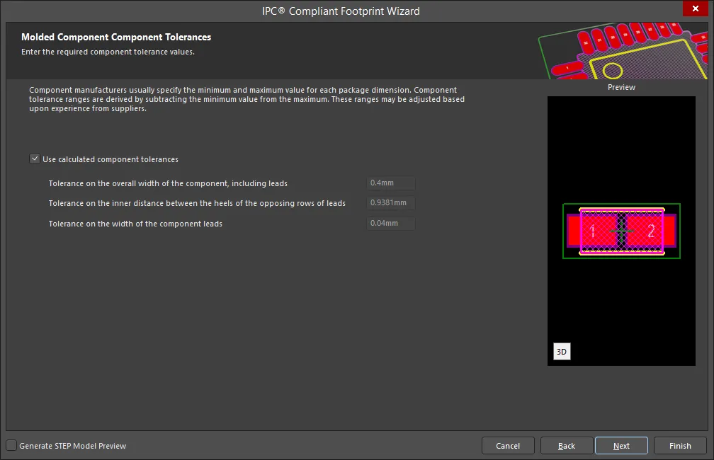
Enter the required values for component tolerances on the Molded Component Component Tolerances page.
Component manufacturers usually specify the minimum and maximum value for each package dimension. Component tolerance ranges are derived by subtracting the minimum value from the maximum value. You can adjust three of these ranges.
If the displayed values are correct for your current situation, enable the Use calculated component tolerances textbox. If the tolerance values need to be adjusted, ensure Use calculated component tolerances is disabled then enter the new values directly in the textboxes next to Tolerance on the overall width of the component, including leads, Tolerance on the inner distance between the heels of the opposing rows of leads, and Tolerance on the width of the component leads.
Molded Component IPC Tolerances
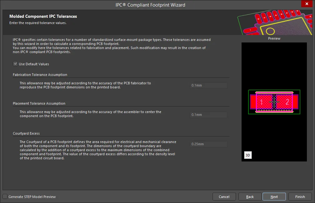
IPC specifies certain tolerances for a number of standardized surface-mount package types. These tolerances are assumed by the Wizard in order to calculate a corresponding PCB footprint. You can modify the tolerances related to fabrication and placement on the Molded Component IPC Tolerances page. Enable Use Default Values to accept the displayed values. You can change the values for Fabrication Tolerance Assumption, Placement Tolerance Assumption, and Courtyard Excess by entering the new values directly in the textboxes.
Modifying the IPC Tolerances may result in PCB footprints that are not IPC compliant.
Molded Component Footprint Dimensions
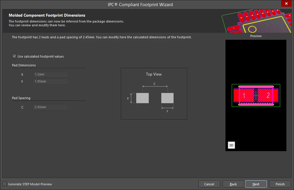
The Molded Component Footprint Dimensions page displays the inferred footprint dimensions using the package dimensions previously defined. To use the displayed values, enable Use calculated footprint values or enter new values for Pad Dimensions and Pad Spacing.
Molded Component Silkscreen Dimensions

The Molded Component Silkscreen Dimensions page displays the inferred silkscreen dimensions using the package dimensions previously defined. You can further define the silkscreen dimensions by entering a new value for the Silkscreen Line Width. Enable Use calculated silkscreen dimensions to use the values displayed or disable the option and enter the desired values.
Molded Component Courtyard, Assembly and Component Body Information
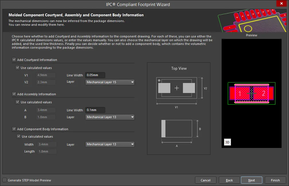
The Molded Component Courtyard, Assembly and Component Body Information page displays the inferred mechanical dimensions using the package dimensions previously defined.
Enable Add Courtyard Information and Add Assembly Information to add courtyard and assembly information to the component drawing. For each, you can use the IPC calculated dimensions or enter new values directly in the textboxes. If desired, enter a new Line Width directly in the textbox. You can also select the mechanical layer for courtyard and assembly by using the drop-down next to Layer and selecting the desired mechanical layer.
A component body contains the volumetric information corresponding to the package dimensions. Enable Add Component Body Information to include this information. Enable Use calculated values to use the values displayed or disable the option and enter new desired values. You can also select the mechanical layer for the component body by using the drop-down next to Layer and selecting the desired mechanical layer.
PLCC
Copy Link
Copied
PLCC
PLCC Square Package Overall Dimensions
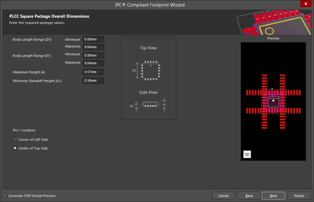
Use the PLCC Square Package Overall Dimensions page to enter the required package values for Body Length Range(s), Maximum Height, and Minimum Standoff Height. Set the Pin 1 Location by selecting either Corner of Left Side or Center of Top Side.
PLCC Square Package Pin Dimensions
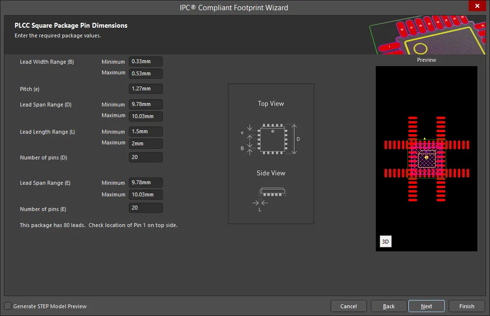
Enter the required values for the package pin dimensions on the PLCC Square Package Pin Dimensions page.
PLCC Square Package Toe Spacing
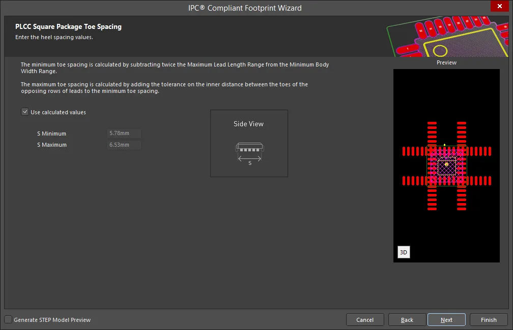
Set the desired heel spacing values on the PLCC Square Package Toe Spacing page.
Enable the Use calculated values checkbox to use the values currently displayed or enter new values directly in the textboxes for S Minimum and S Maximum.
PLCC Square Solder Fillets

Set the required solder fillet values on the PLCC Square Solder Fillets page. Solder fillet refers to the shape of the solder joint between the component lead and the PCB pad. Adequate fillet is required to ensure both the strength and reliability of the solder joints. A solder joint may be described by three fillets: toe, heel, and side.
Minimum values for solder fillets at the toe, heel and side of the component lead have been determined by IPC based on industry empirical knowledge and reliability testing. Enable Use default values to use the values displayed or you can adjust them to suit your specific needs.
Use the Board density Level drop-down to select the desired board density. Choose from Level A - Low density, Level B - Medium density, and Level C - High density. The Preview region is dynamically updated to show your changes.
To update the values for Toe Fillet (JT Min), Heel Fillet (JH Min), and Side Fillet (JS Min), the Use default values option must be disabled. Enter the new values directly in the textboxes.
PLCC Square Component Tolerances

Enter the required values for component tolerances on the PLCC Square Component Tolerances page.
Component manufacturers usually specify the minimum and maximum value for each package dimension. Component tolerance ranges are derived by subtracting the minimum value from the maximum value. You can adjust three of these ranges.
If the displayed values are correct for your current situation, enable the Use calculated component tolerances textbox. If the tolerance values need to be adjusted, ensure Use calculated component tolerances is disabled then enter the new values directly in the textboxes next to Tolerance on the overall width of the component, including leads, Tolerance on the inner distance between the heels of the opposing rows of leads, and Tolerance on the width of the component leads.
PLCC Square IPC Tolerances
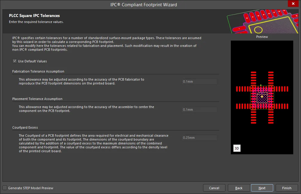
IPC specifies certain tolerances for a number of standardized surface-mount package types. These tolerances are assumed by the Wizard in order to calculate a corresponding PCB footprint. You can modify the tolerances related to fabrication and placement on the PLCC Square IPC Tolerances page. Enable Use Default Values to accept the displayed values. You can change the values for Fabrication Tolerance Assumption, Placement Tolerance Assumption, and Courtyard Excess by entering the new values directly in the textboxes.
Modifying the IPC Tolerances may result in PCB footprints that are not IPC compliant.
PLCC Square Footprint Dimensions
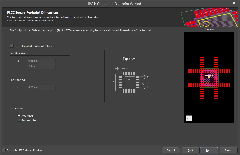
The PLCC Square Footprint Dimensions page displays the inferred footprint dimensions using the package dimensions previously defined. To use the displayed values, enable Use calculated footprint values or enter new values for Pad Dimensions and Pad Spacing.
Select either Rounded or Rectangular for Pad Shape.
PLCC Square Silkscreen Dimensions

The PLCC Square Silkscreen Dimensions page displays the inferred silkscreen dimensions using the package dimensions previously defined. You can further define the silkscreen dimensions by entering a new value for the Silkscreen Line Width. Enable Use calculated silkscreen dimensions to use the values displayed or disable the option and enter the desired values.
PLCC Square Courtyard, Assembly and Component Body Information
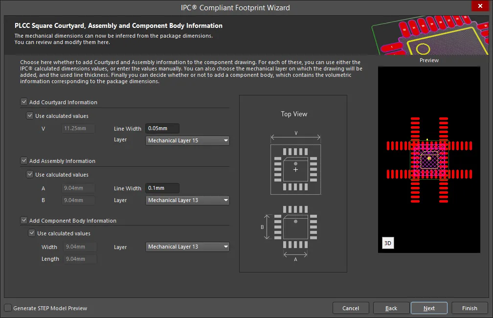
The PLCC Square Courtyard, Assembly and Component Body Information page displays the inferred mechanical dimensions using the package dimensions previously defined.
Enable Add Courtyard Information and Add Assembly Information to add courtyard and assembly information to the component drawing. For each, you can use the IPC calculated dimensions or enter new values directly in the textboxes. If desired, enter a new Line Width directly in the textbox. You can also select the mechanical layer for courtyard and assembly by using the drop-down next to Layer and selecting the desired mechanical layer.
A component body contains the volumetric information corresponding to the package dimensions. Enable Add Component Body Information to include this information. Enable Use calculated values to use the values displayed or disable the option and enter new desired values. You can also select the mechanical layer for the component body by using the drop-down next to Layer and selecting the desired mechanical layer.
PQFN
Copy Link
Copied
PQFN
PQFN Package Overall Dimensions
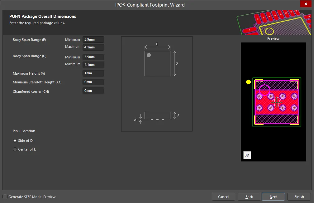
Use the PQFN Package Overall Dimensions page to enter the required package values for Body Span Range(s), Maximum Height, Minimum Standoff Height, and Chamfered corner. Set the Pin 1 Location by selecting either Side of D or Center of E.
PQFN Package Pin Dimensions
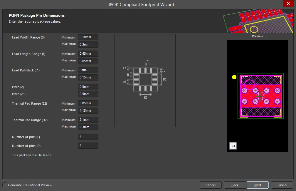
Enter the required values for the package pin dimensions on the PQFN Package Pin Dimensions page.
PQFN Package Power Pad Dimensions
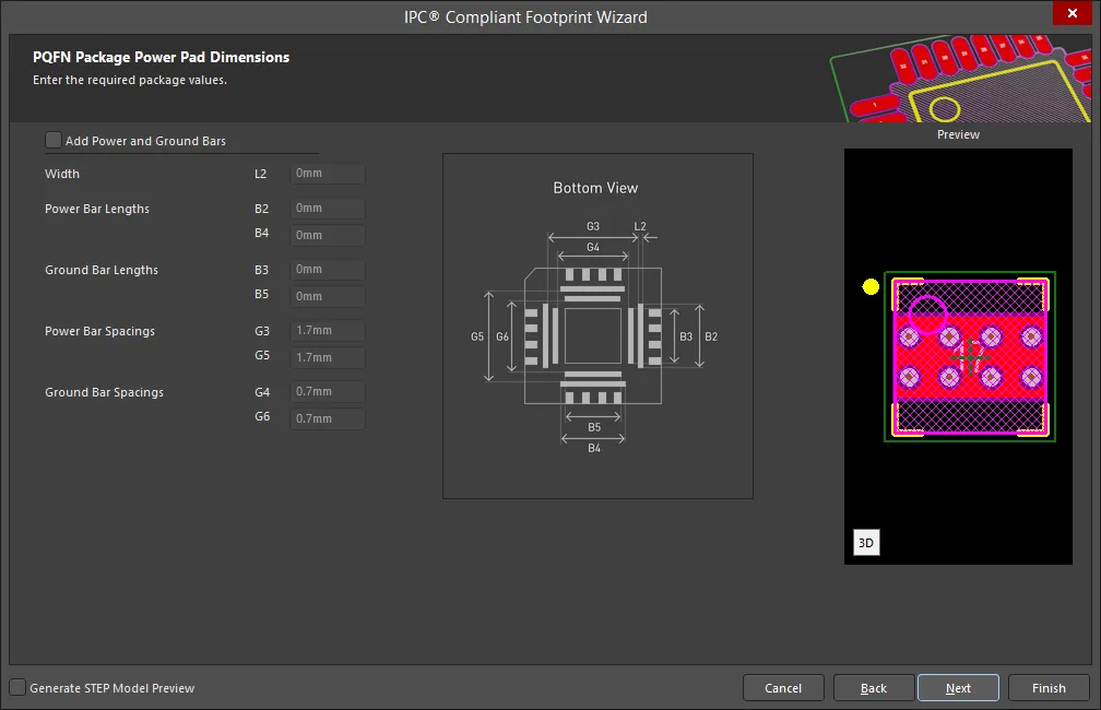
Enter the required values for the power pad dimensions on the PQFN Package Power Pad Dimensions page. Enable Add Power and Ground Bars to access Width, Power Bar Lengths, Ground Bar Lengths, Power Bar Spacings, and Ground Bar Spacings. Enter any required changes in the textboxes.
PQFN Package Heel Spacing

Set the desired heel spacing values on the PQFN Package Heel Spacing page.
Enable the Use calculated values checkbox to use the values currently displayed or enter new values directly in the textboxes for SE Minimum, SE Maximum, SD Minimum, and SD Maximum.
PQFN Solder Fillets
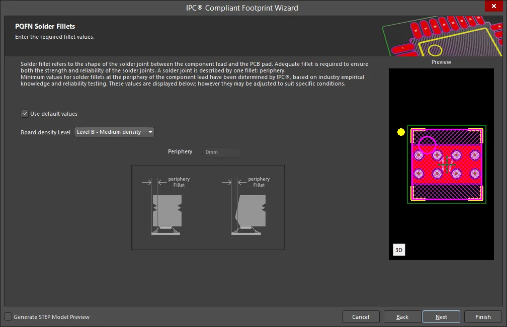
Set the required solder fillet values on the PQFN Solder Fillets page. Solder fillet refers to the shape of the solder joint between the component lead and the PCB pad. Adequate fillet is required to ensure both the strength and reliability of the solder joints. A solder joint may be described by three fillets: toe, heel, and side.
Minimum values for solder fillets at the toe, heel and side of the component lead have been determined by IPC based on industry empirical knowledge and reliability testing. Enable Use default values to use the values displayed or you can adjust them to suit your specific needs.
Use the Board density Level drop-down to select the desired board density. Choose from Level A - Low density, Level B - Medium density, and Level C - High density. The Preview region is dynamically updated to show your changes.
Enter the desired value for Periphery.
PQFN Component Tolerances
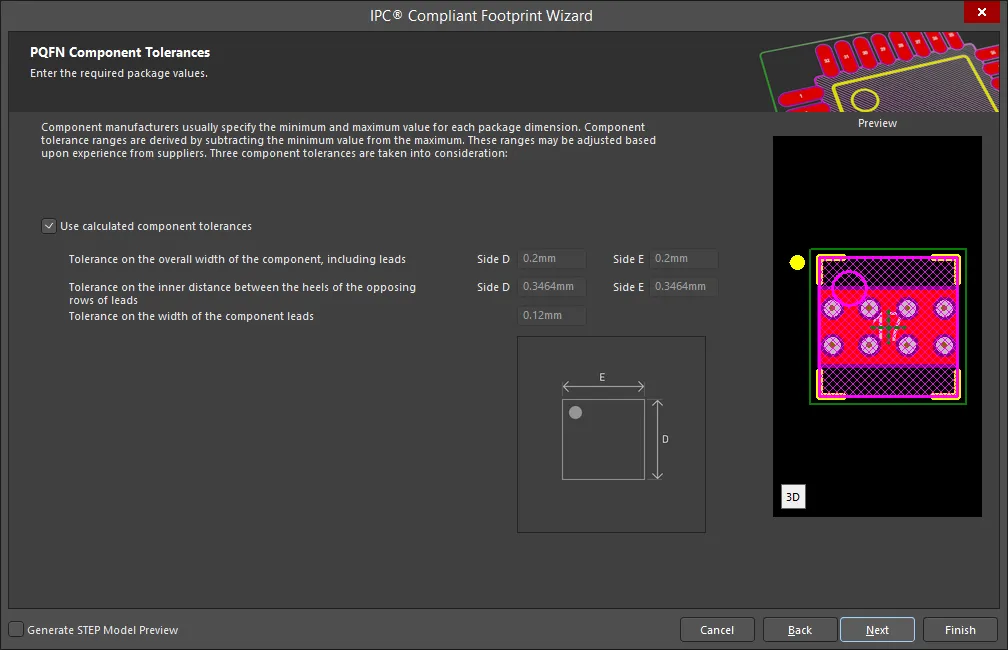
Enter the required values for component tolerances on the PQFN Component Tolerances page.
Component manufacturers usually specify the minimum and maximum value for each package dimension. Component tolerance ranges are derived by subtracting the minimum value from the maximum value. You can adjust three of these ranges.
If the displayed values are correct for your current situation, enable the Use calculated component tolerances textbox. If the tolerance values need to be adjusted, ensure Use calculated component tolerances is disabled then enter the new values directly in the textboxes next to Tolerance on the overall width of the component, including leads, Tolerance on the inner distance between the heels of the opposing rows of leads, and Tolerance on the width of the component leads.
PQFN IPC Tolerances
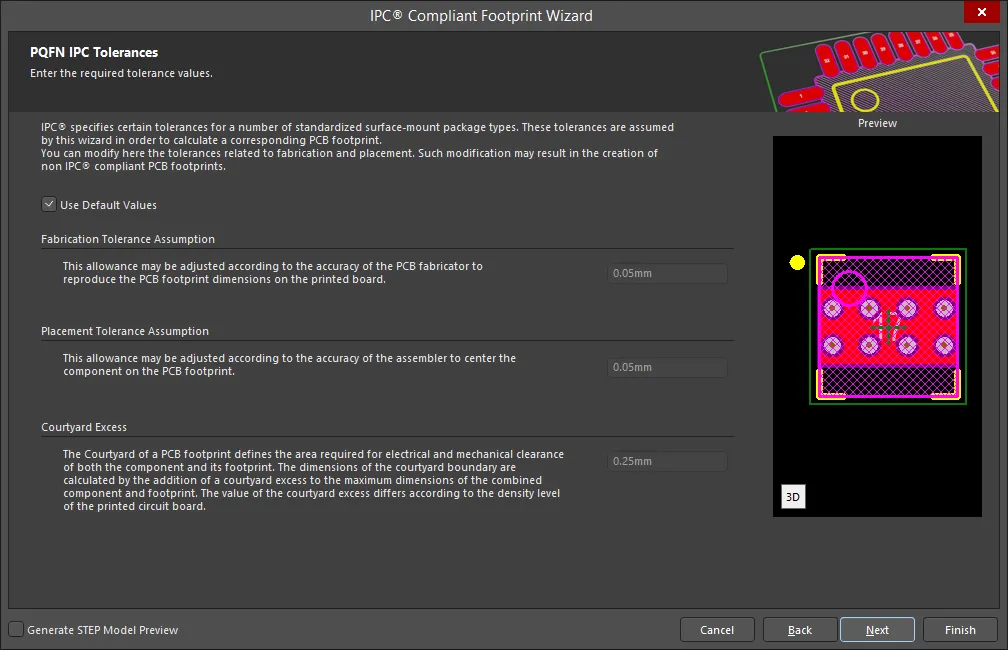
IPC specifies certain tolerances for a number of standardized surface-mount package types. These tolerances are assumed by the Wizard in order to calculate a corresponding PCB footprint. You can modify the tolerances related to fabrication and placement on the PQFN IPC Tolerances page. Enable Use Default Values to accept the displayed values. You can change the values for Fabrication Tolerance Assumption, Placement Tolerance Assumption, and Courtyard Excess by entering the new values directly in the textboxes.
Modifying the IPC Tolerances may result in PCB footprints that are not IPC compliant.
PQFN Footprint Dimensions

The PQFN Footprint Dimensions page displays the inferred footprint dimensions using the package dimensions previously defined. To use the displayed values, enable Use calculated footprint values or enter new values for Pad Dimensions and Pad Spacing.
Select either Rounded or Rectangular for Pad Shape.
PQFN Silkscreen Dimensions

The PQFN Silkscreen Dimensions page displays the inferred silkscreen dimensions using the package dimensions previously defined. You can further define the silkscreen dimensions by entering a new value for the Silkscreen Line Width. Enable Use calculated silkscreen dimensions to use the values displayed or disable the option and enter the desired values.
PQFN Courtyard, Assembly and Component Body Information

The PQFN Courtyard, Assembly and Component Body Information page displays the inferred mechanical dimensions using the package dimensions previously defined.
Enable Add Courtyard Information and Add Assembly Information to add courtyard and assembly information to the component drawing. For each, you can use the IPC calculated dimensions or enter new values directly in the textboxes. If desired, enter a new Line Width directly in the textbox. You can also select the mechanical layer for courtyard and assembly by using the drop-down next to Layer and selecting the desired mechanical layer.
A component body contains the volumetric information corresponding to the package dimensions. Enable Add Component Body Information to include this information. Enable Use calculated values to use the values displayed or disable the option and enter new desired values. You can also select the mechanical layer for the component body by using the drop-down next to Layer and selecting the desired mechanical layer.
PQFP
Copy Link
Copied
PQFP
PQFP Package Overall Dimensions

Use the PQFP Package Overall Dimensions page to enter the required package values for Lead Span Range(s), Maximum Height, and Minimum Standoff Height. Set the Pin 1 Location by selecting either Side of D or Center of E.
PQFP Package Pin Dimensions
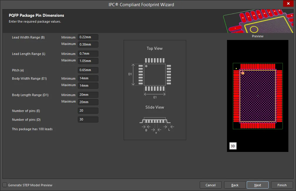
Enter the required values for the package pin dimensions on the PQFP Package Pin Dimensions page.
PQFP Package Thermal Pad Dimensions
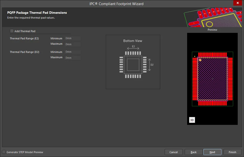
Enter the required values for the thermal pad dimensions on the PQFP Package Thermal Pad Dimensions page. Enable Add Thermal Pad to access the Thermal Pad Range options and enter any required changes in the textboxes.
PQFP Package Heel Spacing

Set the desired heel spacing values on the PQFP Package Heel Spacing page.
Enable the Use calculated values checkbox to use the values currently displayed or enter new values directly in the textboxes for SE Minimum, SE Maximum, SD Minimum, and SD Maximum.
PQFP Solder Fillets

Set the required solder fillet values on the PQFP Solder Fillets page. Solder fillet refers to the shape of the solder joint between the component lead and the PCB pad. Adequate fillet is required to ensure both the strength and reliability of the solder joints. A solder joint may be described by three fillets: toe, heel, and side.
Minimum values for solder fillets at the toe, heel and side of the component lead have been determined by IPC based on industry empirical knowledge and reliability testing. Enable Use default values to use the values displayed or you can adjust them to suit your specific needs.
Use the Board density Level drop-down to select the desired board density. Choose from Level A - Low density, Level B - Medium density, and Level C - High density. The Preview region is dynamically updated to show your changes.
To update the values for Toe Fillet (JT Min), Heel Fillet (JH Min), and Side Fillet (JS Min), the Use default values option must be disabled. Enter the new values directly in the textboxes.
PQFP Component Tolerances
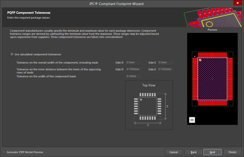
Enter the required values for component tolerances on the PQFP Component Tolerances page.
Component manufacturers usually specify the minimum and maximum value for each package dimension. Component tolerance ranges are derived by subtracting the minimum value from the maximum value. You can adjust three of these ranges.
If the displayed values are correct for your current situation, enable the Use calculated component tolerances textbox. If the tolerance values need to be adjusted, ensure Use calculated component tolerances is disabled then enter the new values directly in the textboxes next to Tolerance on the overall width of the component, including leads, Tolerance on the inner distance between the heels of the opposing rows of leads, and Tolerance on the width of the component leads.
PQFP IPC Tolerances
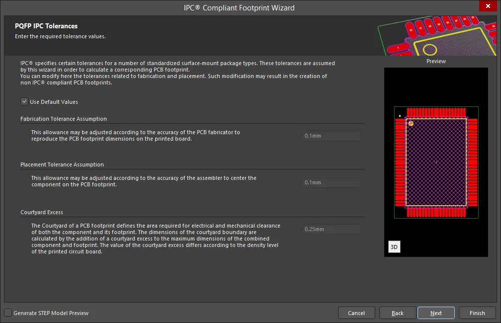
IPC specifies certain tolerances for a number of standardized surface-mount package types. These tolerances are assumed by the Wizard in order to calculate a corresponding PCB footprint. You can modify the tolerances related to fabrication and placement on the PQFP IPC Tolerances page. Enable Use Default Values to accept the displayed values. You can change the values for Fabrication Tolerance Assumption, Placement Tolerance Assumption, and Courtyard Excess by entering the new values directly in the textboxes.
Modifying the IPC Tolerances may result in PCB footprints that are not IPC compliant.
PQFP Footprint Dimensions
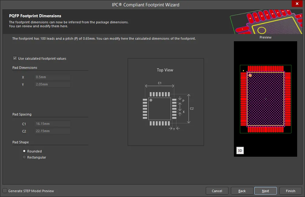
The PQFP Footprint Dimensions page displays the inferred footprint dimensions using the package dimensions previously defined. To use the displayed values, enable Use calculated footprint values or enter new values for Pad Dimensions and Pad Spacing.
Select either Rounded or Rectangular for Pad Shape.
PQFP Silkscreen Dimensions

The PQFP Silkscreen Dimensions page displays the inferred silkscreen dimensions using the package dimensions previously defined. You can further define the silkscreen dimensions by entering a new value for the Silkscreen Line Width. Enable Use calculated silkscreen dimensions to use the values displayed or disable the option and enter the desired values.
PQFP Courtyard, Assembly and Component Body Information
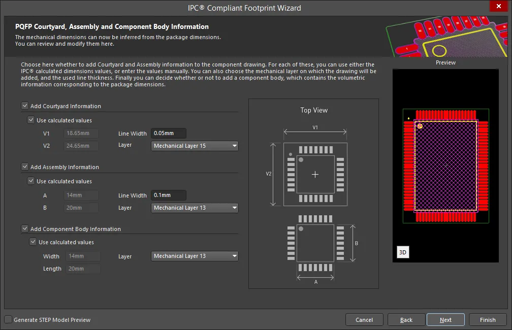
The PQFP Courtyard, Assembly and Component Body Information page displays the inferred mechanical dimensions using the package dimensions previously defined.
Enable Add Courtyard Information and Add Assembly Information to add courtyard and assembly information to the component drawing. For each, you can use the IPC calculated dimensions or enter new values directly in the textboxes. If desired, enter a new Line Width directly in the textbox. You can also select the mechanical layer for courtyard and assembly by using the drop-down next to Layer and selecting the desired mechanical layer.
A component body contains the volumetric information corresponding to the package dimensions. Enable Add Component Body Information to include this information. Enable Use calculated values to use the values displayed or disable the option and enter new desired values. You can also select the mechanical layer for the component body by using the drop-down next to Layer and selecting the desired mechanical layer.
PSON
Copy Link
Copied
PSON
PSON Package Dimensions
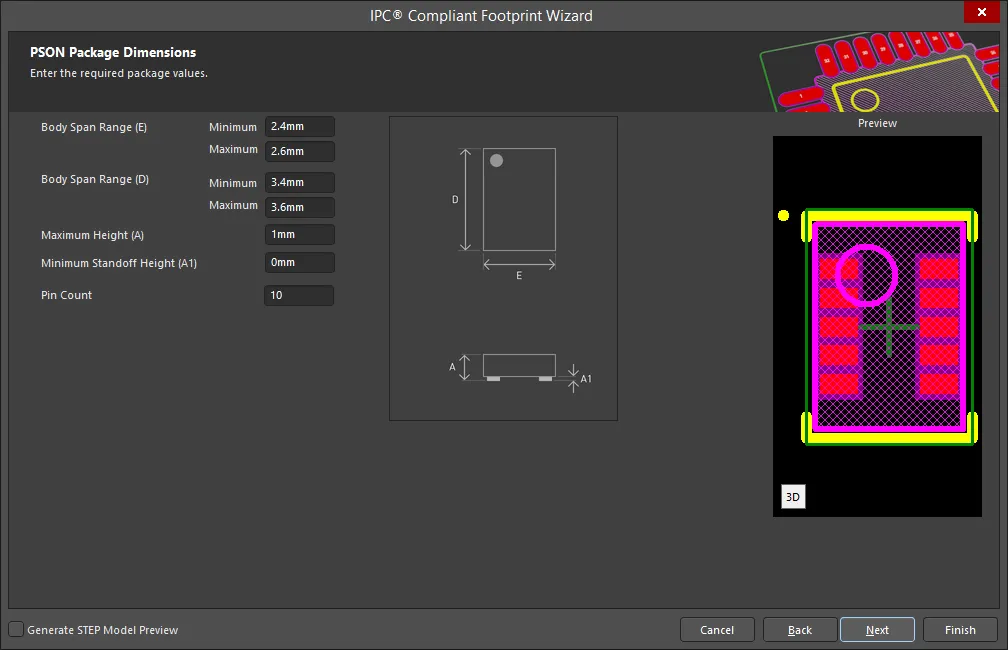
Use the PSON Package Dimensions page to enter the required package values for Body Span Range(s), Maximum Height, Minimum Standoff Height, and Pin Count.
PSON Package Thermal Pad Dimensions
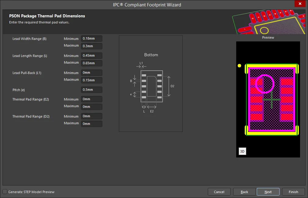
Enter the required values for the thermal pad dimensions on the PSON Package Thermal Pad Dimensions page. Enter any required changes in the textboxes.
PSON Solder Fillets
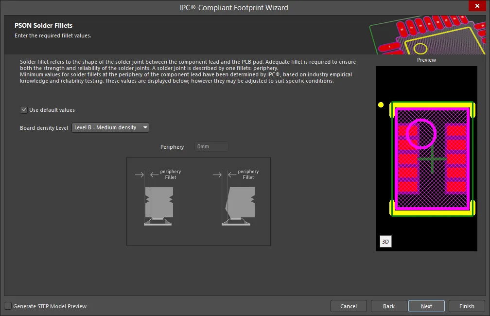
Set the required solder fillet values on the PSON Solder Fillets page. Solder fillet refers to the shape of the solder joint between the component lead and the PCB pad. Adequate fillet is required to ensure both the strength and reliability of the solder joints. A solder joint may be described by three fillets: toe, heel, and side.
Minimum values for solder fillets at the toe, heel and side of the component lead have been determined by IPC based on industry empirical knowledge and reliability testing. Enable Use default values to use the values displayed or you can adjust them to suit your specific needs.
Use the Board density Level drop-down to select the desired board density. Choose from Level A - Low density, Level B - Medium density, and Level C - High density. The Preview region is dynamically updated to show your changes.
Enter the value for Periphery in the textbox.
PSON Component Tolerances

Enter the required values for component tolerances on the PSON Component Tolerances page.
Component manufacturers usually specify the minimum and maximum value for each package dimension. Component tolerance ranges are derived by subtracting the minimum value from the maximum value. You can adjust three of these ranges.
If the displayed values are correct for your current situation, enable the Use calculated component tolerances textbox. If the tolerance values need to be adjusted, ensure Use calculated component tolerances is disabled then enter the new values directly in the textboxes next to Tolerance on the overall width of the component, including leads, Tolerance on the inner distance between the heels of the opposing rows of leads, and Tolerance on the width of the component leads.
PSON IPC Tolerances
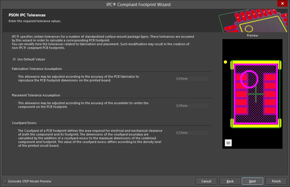
IPC specifies certain tolerances for a number of standardized surface-mount package types. These tolerances are assumed by the Wizard in order to calculate a corresponding PCB footprint. You can modify the tolerances related to fabrication and placement on the PSON IPC Tolerances page. Enable Use Default Values to accept the displayed values. You can change the values for Fabrication Tolerance Assumption, Placement Tolerance Assumption, and Courtyard Excess by entering the new values directly in the textboxes.
Modifying the IPC Tolerances may result in PCB footprints that are not IPC compliant.
PSON Footprint Dimensions

The PSON Footprint Dimensions page displays the inferred footprint dimensions using the package dimensions previously defined. To use the displayed values, enable Use calculated footprint values or disable and enter new values for Pad Dimensions and Pad Spacing.
PSON Footprint Paste Fill Dimensions

The PSON Footprint Paste Fill Dimensions page displays the inferred footprint paste fill dimensions using the package dimensions previously defined. To use the displayed values, enable Use calculated footprint values or disable and enter new values for Paste Fill Dimensions.
PSON Silkscreen Dimensions
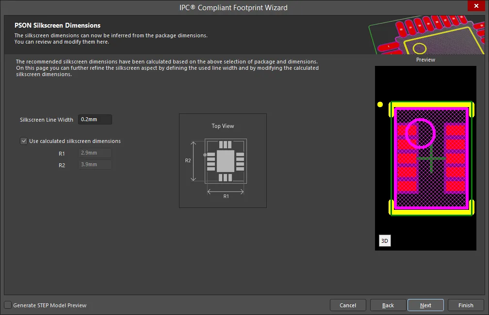
The PSON Silkscreen Dimensions page displays the inferred silkscreen dimensions using the package dimensions previously defined. You can further define the silkscreen dimensions by entering a new value for the Silkscreen Line Width. Enable Use calculated silkscreen dimensions to use the values displayed or disable the option and enter the desired values.
PSON Courtyard, Assembly and Component Body Information
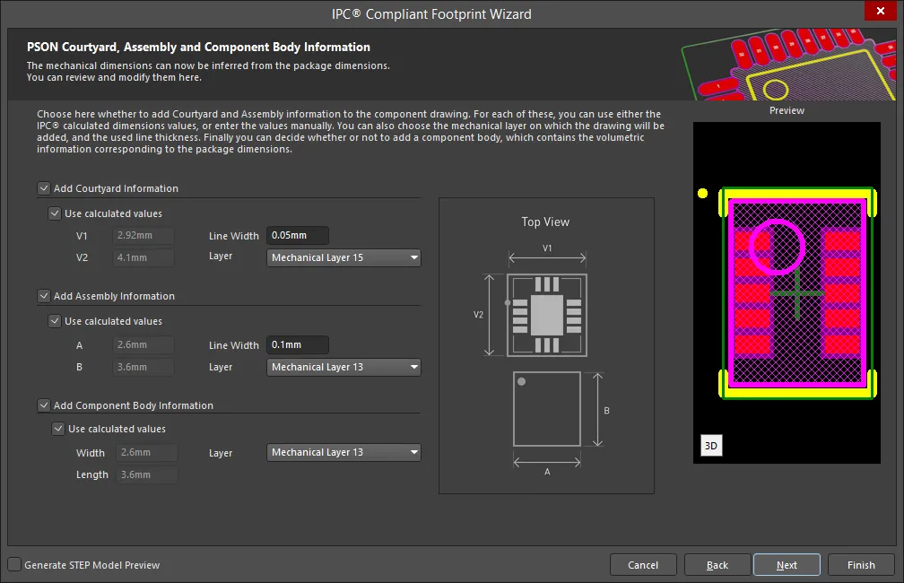
The PSON Courtyard, Assembly and Component Body Information page displays the inferred mechanical dimensions using the package dimensions previously defined.
Enable Add Courtyard Information and Add Assembly Information to add courtyard and assembly information to the component drawing. For each, you can use the IPC calculated dimensions or enter new values directly in the textboxes. If desired, enter a new Line Width directly in the textbox. You can also select the mechanical layer for courtyard and assembly by using the drop-down next to Layer and selecting the desired mechanical layer.
A component body contains the volumetric information corresponding to the package dimensions. Enable Add Component Body Information to include this information. Enable Use calculated values to use the values displayed or disable the option and enter new desired values. You can also select the mechanical layer for the component body by using the drop-down next to Layer and selecting the desired mechanical layer.
QFN
Copy Link
Copied
QFN
QFN Package Overall Dimensions
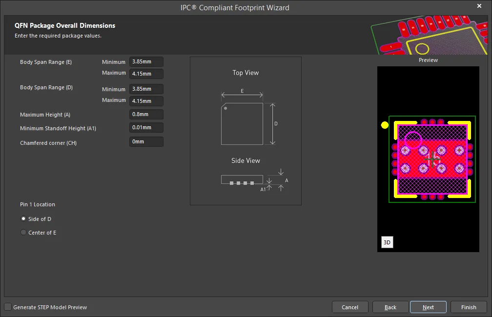
Use the QFN Package Overall Dimensions page to enter the required package values for Body Span Range(s), Maximum Height, Minimum Standoff Height, and Chamfered corner. Set the Pin 1 Location by selecting either Side of D or Center of E.
QFN Package Pin Dimensions

Enter the required values for the package pin dimensions on the QFN Package Pin Dimensions page.
QFN Package Power Pad Dimensions
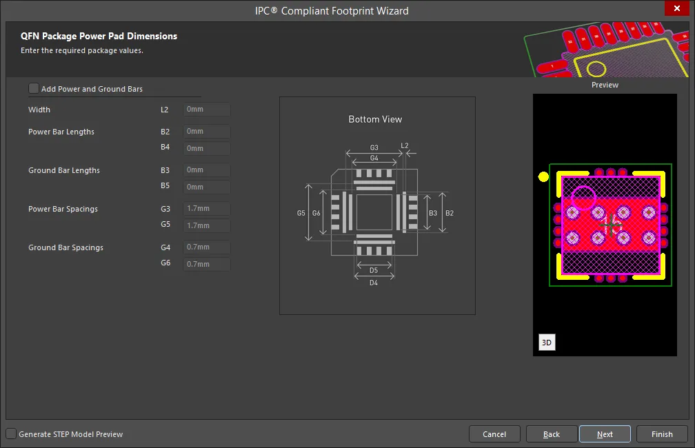
Enter the required values for the power pad dimensions on the QFN Package Power Pad Dimensions page. Enable Add Power and Ground Bars to access Width, Power Bar Lengths, Ground Bar Lengths, Power Bar Spacings, and Ground Bar Spacings. Enter any required changes in the textboxes.
QFN Package Heel Spacing

Set the desired heel spacing values on the QFN Package Heel Spacing page.
Enable the Use calculated values checkbox to use the values currently displayed or enter new values directly in the textboxes for SE Minimum, SE Maximum, SD Minimum, and SD Maximum.
QFN Solder Fillets
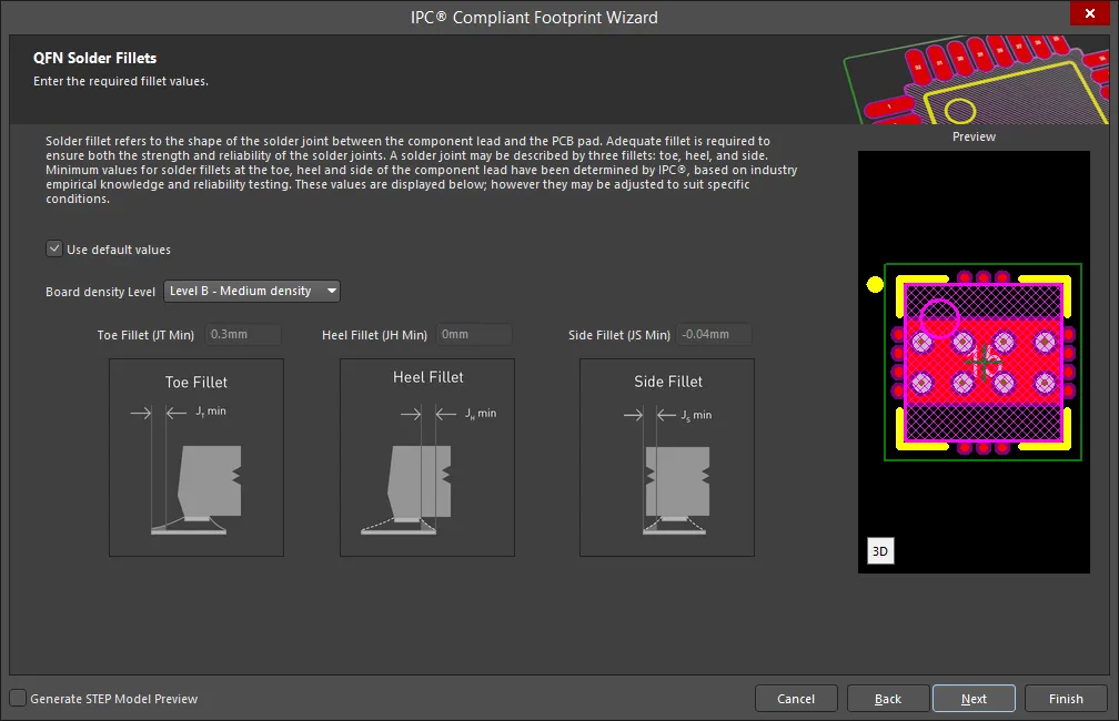
Set the required solder fillet values on the QFN Solder Fillets page. Solder fillet refers to the shape of the solder joint between the component lead and the PCB pad. Adequate fillet is required to ensure both the strength and reliability of the solder joints. A solder joint may be described by three fillets: toe, heel, and side.
Minimum values for solder fillets at the toe, heel and side of the component lead have been determined by IPC based on industry empirical knowledge and reliability testing. Enable Use default values to use the values displayed or you can adjust them to suit your specific needs.
Use the Board density Level drop-down to select the desired board density. Choose from Level A - Low density, Level B - Medium density, and Level C - High density. The Preview region is dynamically updated to show your changes.
To update the values for Toe Fillet (JT Min), Heel Fillet (JH Min), and Side Fillet (JS Min), the Use default values option must be disabled. Enter the new values directly in the textboxes.
QFN Component Tolerances
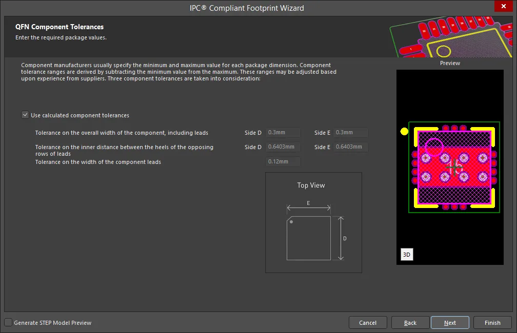
Enter the required values for component tolerances on the QFN Component Tolerances page.
Component manufacturers usually specify the minimum and maximum value for each package dimension. Component tolerance ranges are derived by subtracting the minimum value from the maximum value. You can adjust three of these ranges.
If the displayed values are correct for your current situation, enable the Use calculated component tolerances textbox. If the tolerance values need to be adjusted, ensure Use calculated component tolerances is disabled then enter the new values directly in the textboxes next to Tolerance on the overall width of the component, including leads, Tolerance on the inner distance between the heels of the opposing rows of leads, and Tolerance on the width of the component leads.
QFN IPC Tolerances

IPC specifies certain tolerances for a number of standardized surface-mount package types. These tolerances are assumed by the Wizard in order to calculate a corresponding PCB footprint. You can modify the tolerances related to fabrication and placement on the QFN IPC Tolerances page. Enable Use Default Values to accept the displayed values. You can change the values for Fabrication Tolerance Assumption, Placement Tolerance Assumption, and Courtyard Excess by entering the new values directly in the textboxes.
Modifying the IPC Tolerances may result in PCB footprints that are not IPC compliant.
QFN Footprint Dimensions

The QFN Footprint Dimensions page displays the inferred footprint dimensions using the package dimensions previously defined. To use the displayed values, enable Use calculated footprint values or enter new values for Pad Dimensions and Pad Spacing.
Select either Rounded or Rectangular for Pad Shape.
QFN Silkscreen Dimensions

The QFN Silkscreen Dimensions page displays the inferred silkscreen dimensions using the package dimensions previously defined. You can further define the silkscreen dimensions by entering a new value for the Silkscreen Line Width. Enable Use calculated silkscreen dimensions to use the values displayed or disable the option and enter the desired values.
QFN Courtyard, Assembly and Component Body Information

The QFN Courtyard, Assembly and Component Body Information page displays the inferred mechanical dimensions using the package dimensions previously defined.
Enable Add Courtyard Information and Add Assembly Information to add courtyard and assembly information to the component drawing. For each, you can use the IPC calculated dimensions or enter new values directly in the textboxes. If desired, enter a new Line Width directly in the textbox. You can also select the mechanical layer for courtyard and assembly by using the drop-down next to Layer and selecting the desired mechanical layer.
A component body contains the volumetric information corresponding to the package dimensions. Enable Add Component Body Information to include this information. Enable Use calculated values to use the values displayed or disable the option and enter new desired values. You can also select the mechanical layer for the component body by using the drop-down next to Layer and selecting the desired mechanical layer.
QFN-2ROW
Copy Link
Copied
QFN-2ROW
QFN-2ROW Package Overall Dimensions

Use the QFN-2ROW Package Overall Dimensions page to enter the required package values for Body Span Range(s), Maximum Height, Minimum Standoff Height, and Total number of pins. Enable Calculate number of pins in rows to use the displayed values or disable and enter new Number of pins values.
QFN-2ROW Package Pin Dimensions
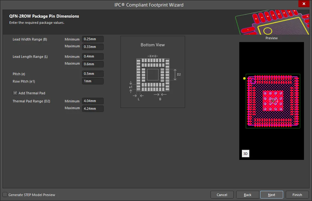
Enter the required values for the package pin dimensions on the QFN-2ROW Package Pin Dimensions page.
Enter the Lead Width Range, Lead Length Range, Pitch, and Row Pitch.
Enable Add Thermal Pad to add a thermal pad then enter the Thermal Pad Range values.
QFN-2ROW Package Heel Spacing
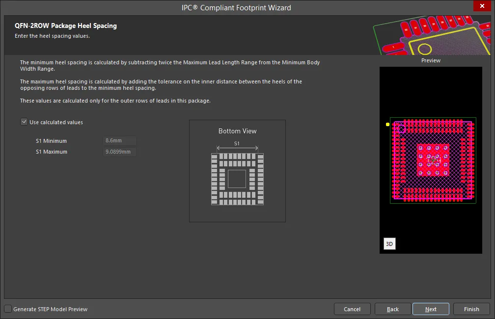
Set the desired heel spacing values on the QFN-2ROW Package Heel Spacing page.
Enable the Use calculated values checkbox to use the values currently displayed or enter new values directly in the textboxes for S1 Minimum and S1 Maximum.
QFN-2ROW Solder Fillets
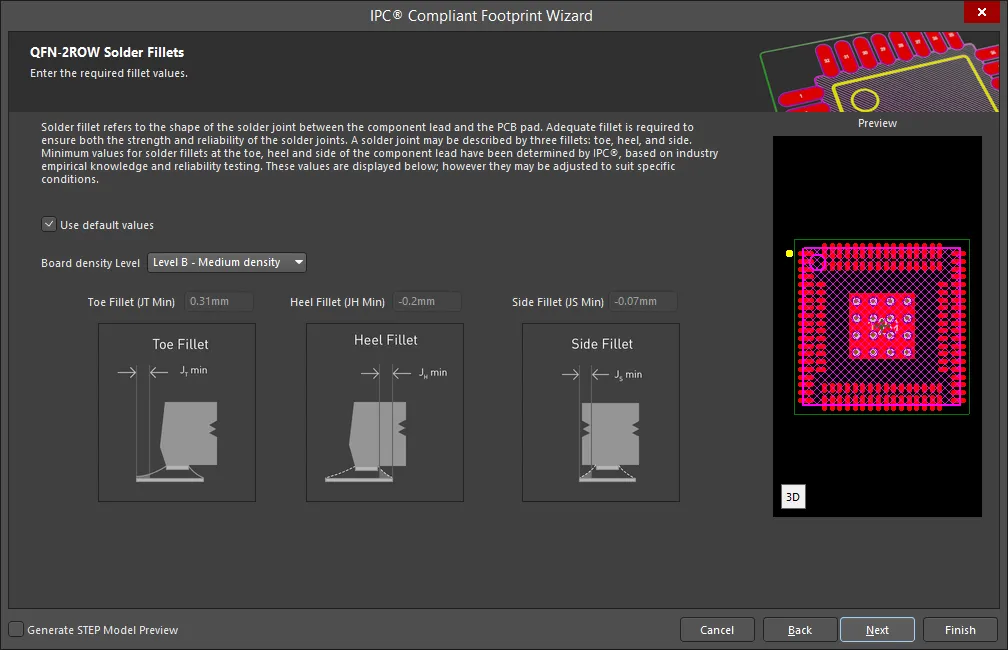
Set the required solder fillet values on the QFN-2ROW Solder Fillets page. Solder fillet refers to the shape of the solder joint between the component lead and the PCB pad. Adequate fillet is required to ensure both the strength and reliability of the solder joints. A solder joint may be described by three fillets: toe, heel, and side.
Minimum values for solder fillets at the toe, heel and side of the component lead have been determined by IPC based on industry empirical knowledge and reliability testing. Enable Use default values to use the values displayed or you can adjust them to suit your specific needs.
Use the Board density Level drop-down to select the desired board density. Choose from Level A - Low density, Level B - Medium density, and Level C - High density. The Preview region is dynamically updated to show your changes.
To update the values for Toe Fillet (JT Min), Heel Fillet (JH Min), and Side Fillet (JS Min), the Use default values option must be disabled. Enter the new values directly in the textboxes.
QFN-2ROW Component Tolerances
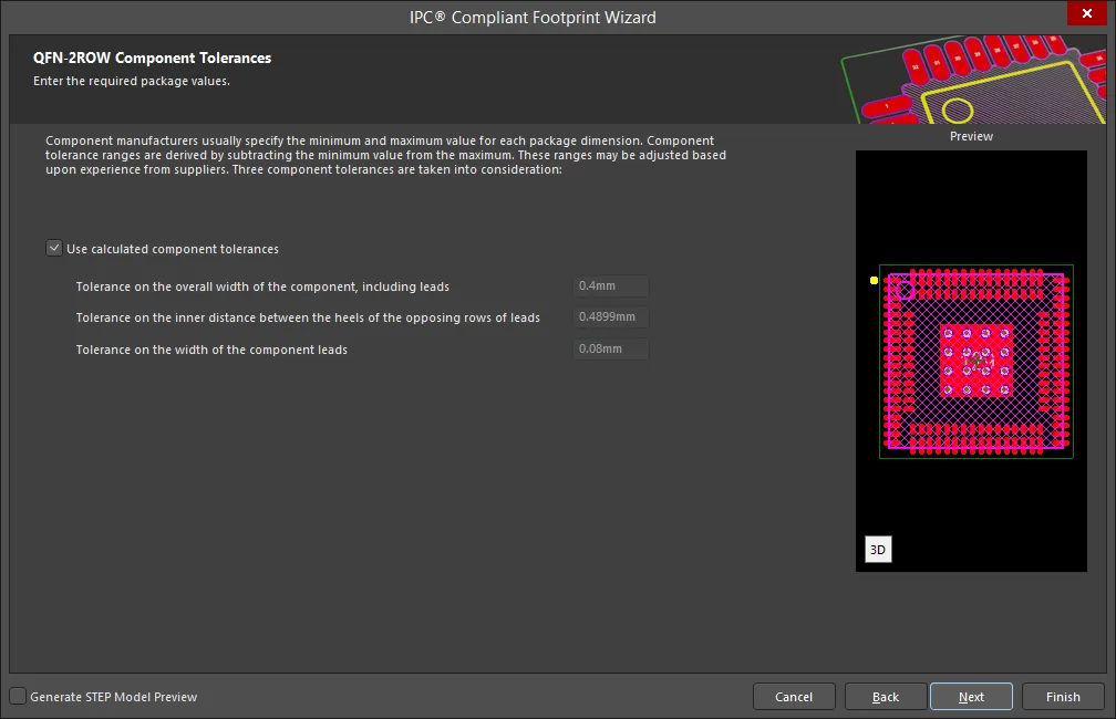
Enter the required values for component tolerances on the QFN-2ROW Component Tolerances page.
Component manufacturers usually specify the minimum and maximum value for each package dimension. Component tolerance ranges are derived by subtracting the minimum value from the maximum value. You can adjust three of these ranges.
If the displayed values are correct for your current situation, enable the Use calculated component tolerances textbox. If the tolerance values need to be adjusted, ensure Use calculated component tolerances is disabled then enter the new values directly in the textboxes next to Tolerance on the overall width of the component, including leads, Tolerance on the inner distance between the heels of the opposing rows of leads, and Tolerance on the width of the component leads.
QFN-2ROW IPC Tolerances
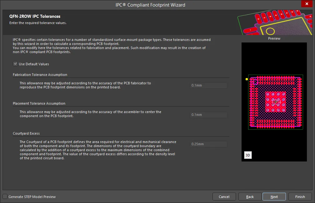
IPC specifies certain tolerances for a number of standardized surface-mount package types. These tolerances are assumed by the Wizard in order to calculate a corresponding PCB footprint. You can modify the tolerances related to fabrication and placement on the QFN-2ROW IPC Tolerances page. Enable Use Default Values to accept the displayed values. You can change the values for Fabrication Tolerance Assumption, Placement Tolerance Assumption, and Courtyard Excess by entering the new values directly in the textboxes.
Modifying the IPC Tolerances may result in PCB footprints that are not IPC compliant.
QFN-2ROW Footprint Dimensions
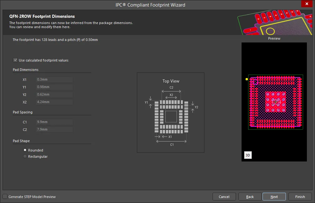
The QFN-2ROW Footprint Dimensions page displays the inferred footprint dimensions using the package dimensions previously defined. To use the displayed values, enable Use calculated footprint values or enter new values for Pad Dimensions and Pad Spacing.
Select either Rounded or Rectangular for Pad Shape.
QFN-2ROW Courtyard, Assembly and Component Body Information
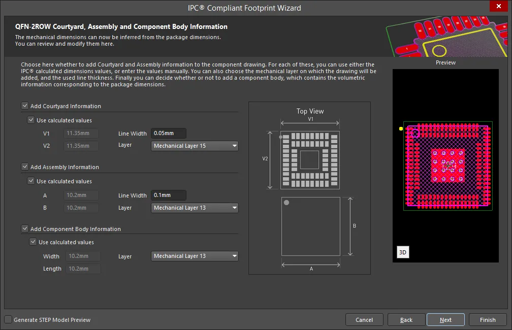
The QFN-2ROW Courtyard, Assembly and Component Body Information page displays the inferred mechanical dimensions using the package dimensions previously defined.
Enable Add Courtyard Information and Add Assembly Information to add courtyard and assembly information to the component drawing. For each, you can use the IPC calculated dimensions or enter new values directly in the textboxes. If desired, enter a new Line Width directly in the textbox. You can also select the mechanical layer for courtyard and assembly by using the drop-down next to Layer and selecting the desired mechanical layer.
A component body contains the volumetric information corresponding to the package dimensions. Enable Add Component Body Information to include this information. Enable Use calculated values to use the values displayed or disable the option and enter new desired values. You can also select the mechanical layer for the component body by using the drop-down next to Layer and selecting the desired mechanical layer.
SODFL
Copy Link
Copied
SODFL
SODFL Package Dimensions
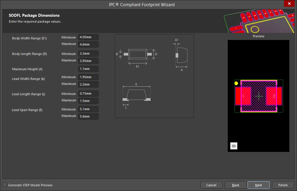
Use the SODFL Package Dimensions page to enter the required package values for Body Width Range, Body Length Range, Maximum Height, Lead Width Range, Lead Length Range, and Lead Span Range.
SODFL Package Heel Spacing

Set the desired heel spacing values on the SODFL Package Heel Spacing page.
Enable the Use calculated values checkbox to use the values currently displayed or enter new values directly in the textboxes for S Minimum and S Maximum.
SODFL Solder Fillets

Set the required solder fillet values on the SODFL Solder Fillets page. Solder fillet refers to the shape of the solder joint between the component lead and the PCB pad. Adequate fillet is required to ensure both the strength and reliability of the solder joints. A solder joint may be described by three fillets: toe, heel, and side.
Minimum values for solder fillets at the toe, heel and side of the component lead have been determined by IPC based on industry empirical knowledge and reliability testing. Enable Use default values to use the values displayed or you can adjust them to suit your specific needs.
Use the Board density Level drop-down to select the desired board density. Choose from Level A - Low density, Level B - Medium density, and Level C - High density. The Preview region is dynamically updated to show your changes.
To update the values for Toe Fillet (JT Min), Heel Fillet (JH Min), and Side Fillet (JS Min), the Use default values option must be disabled. Enter the new values directly in the textboxes.
SODFL Component Tolerances

Enter the required values for component tolerances on the SODFL Component Tolerances page.
Component manufacturers usually specify the minimum and maximum value for each package dimension. Component tolerance ranges are derived by subtracting the minimum value from the maximum value. You can adjust three of these ranges.
If the displayed values are correct for your current situation, enable the Use calculated component tolerances textbox. If the tolerance values need to be adjusted, ensure Use calculated component tolerances is disabled then enter the new values directly in the textboxes next to Tolerance on the overall width of the component, including leads, Tolerance on the inner distance between the heels of the opposing rows of leads, and Tolerance on the width of the component leads.
SODFL IPC Tolerances
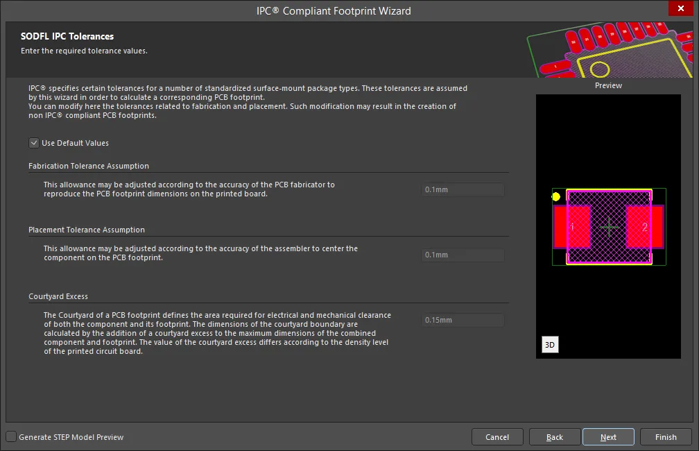
IPC specifies certain tolerances for a number of standardized surface-mount package types. These tolerances are assumed by the Wizard in order to calculate a corresponding PCB footprint. You can modify the tolerances related to fabrication and placement on the SODFL IPC Tolerances page. Enable Use Default Values to accept the displayed values. You can change the values for Fabrication Tolerance Assumption, Placement Tolerance Assumption, and Courtyard Excess by entering the new values directly in the textboxes.
Modifying the IPC Tolerances may result in PCB footprints that are not IPC compliant.
SODFL Footprint Dimensions
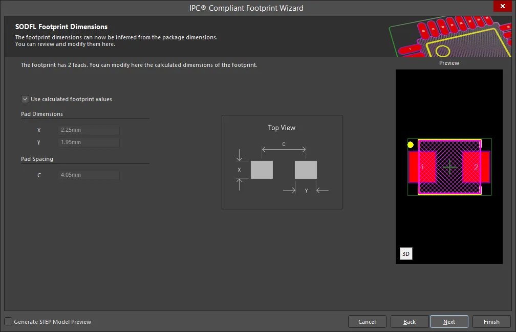
The SODFL Footprint Dimensions page displays the inferred footprint dimensions using the package dimensions previously defined. To use the displayed values, enable Use calculated footprint values or enter new values for Pad Dimensions and Pad Spacing.
SODFL Silkscreen Dimensions

The SODFL Silkscreen Dimensions page displays the inferred silkscreen dimensions using the package dimensions previously defined. You can further define the silkscreen dimensions by entering a new value for the Silkscreen Line Width. Enable Use calculated silkscreen dimensions to use the values displayed or disable the option and enter the desired values.
SODFL Courtyard, Assembly and Component Body Information

The SODFL Courtyard, Assembly and Component Body Information page displays the inferred mechanical dimensions using the package dimensions previously defined.
Enable Add Courtyard Information and Add Assembly Information to add courtyard and assembly information to the component drawing. For each, you can use the IPC calculated dimensions or enter new values directly in the textboxes. If desired, enter a new Line Width directly in the textbox. You can also select the mechanical layer for courtyard and assembly by using the drop-down next to Layer and selecting the desired mechanical layer.
A component body contains the volumetric information corresponding to the package dimensions. Enable Add Component Body Information to include this information. Enable Use calculated values to use the values displayed or disable the option and enter new desired values. You can also select the mechanical layer for the component body by using the drop-down next to Layer and selecting the desired mechanical layer.
SOIC
Copy Link
Copied
SOIC
SOIC Package Dimensions
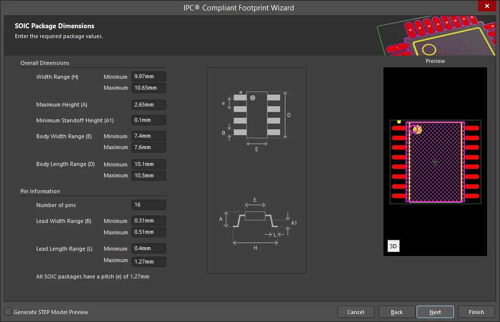
Use the SOIC Package Dimensions page to enter the required package values for Overall Dimensions and Pin Information.
SOIC Package Thermal Pad Dimensions

Enter the required values for the thermal pad dimensions on the SOIC Package Thermal Pad Dimensions page. Enable Add Thermal Pad if required and enter any changes for Thermal Pad Range(s).
SOIC Package Heel Spacing
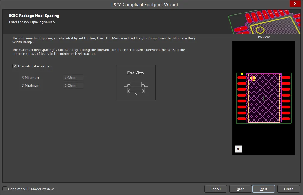
Set the desired heel spacing values on the SOIC Package Heel Spacing page.
Enable the Use calculated values checkbox to use the values currently displayed or enter new values directly in the textboxes for S Minimum and S Maximum.
SOIC Solder Fillets
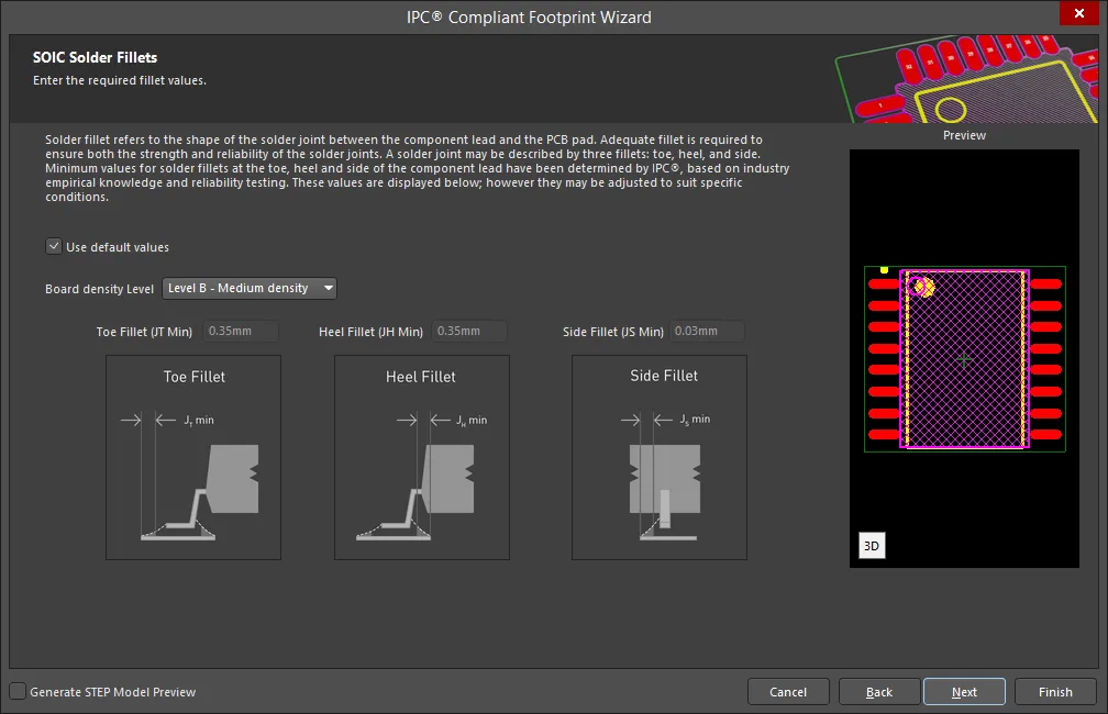
Set the required solder fillet values on the SOIC Solder Fillets page. Solder fillet refers to the shape of the solder joint between the component lead and the PCB pad. Adequate fillet is required to ensure both the strength and reliability of the solder joints. A solder joint may be described by three fillets: toe, heel, and side.
Minimum values for solder fillets at the toe, heel and side of the component lead have been determined by IPC based on industry empirical knowledge and reliability testing. Enable Use default values to use the values displayed or you can adjust them to suit your specific needs.
Use the Board density Level drop-down to select the desired board density. Choose from Level A - Low density, Level B - Medium density, and Level C - High density. The Preview region is dynamically updated to show your changes.
To update the values for Toe Fillet (JT Min), Heel Fillet (JH Min), and Side Fillet (JS Min), the Use default values option must be disabled. Enter the new values directly in the textboxes.
SOIC Component Tolerances

Enter the required values for component tolerances on the SOIC Component Tolerances page.
Component manufacturers usually specify the minimum and maximum value for each package dimension. Component tolerance ranges are derived by subtracting the minimum value from the maximum value. You can adjust three of these ranges.
If the displayed values are correct for your current situation, enable the Use calculated component tolerances textbox. If the tolerance values need to be adjusted, ensure Use calculated component tolerances is disabled then enter the new values directly in the textboxes next to Tolerance on the overall width of the component, including leads, Tolerance on the inner distance between the heels of the opposing rows of leads, and Tolerance on the width of the component leads.
SOIC IPC Tolerances

IPC specifies certain tolerances for a number of standardized surface-mount package types. These tolerances are assumed by the Wizard in order to calculate a corresponding PCB footprint. You can modify the tolerances related to fabrication and placement on the SOIC IPC Tolerances page. Enable Use Default Values to accept the displayed values. You can change the values for Fabrication Tolerance Assumption, Placement Tolerance Assumption, and Courtyard Excess by entering the new values directly in the textboxes.
Modifying the IPC Tolerances may result in PCB footprints that are not IPC compliant.
SOIC Footprint Dimensions

The SOIC Footprint Dimensions page displays the inferred footprint dimensions using the package dimensions previously defined. To use the displayed values, enable Use calculated footprint values or enter new values for Pad Dimensions and Pad Spacing.
Select either Rounded or Rectangular for Pad Shape.
SOIC Silkscreen Dimensions
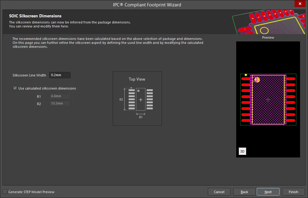
The SOIC Silkscreen Dimensions page displays the inferred silkscreen dimensions using the package dimensions previously defined. You can further define the silkscreen dimensions by entering a new value for the Silkscreen Line Width. Enable Use calculated silkscreen dimensions to use the values displayed or disable the option and enter the desired values.
SOIC Courtyard, Assembly and Component Body Information
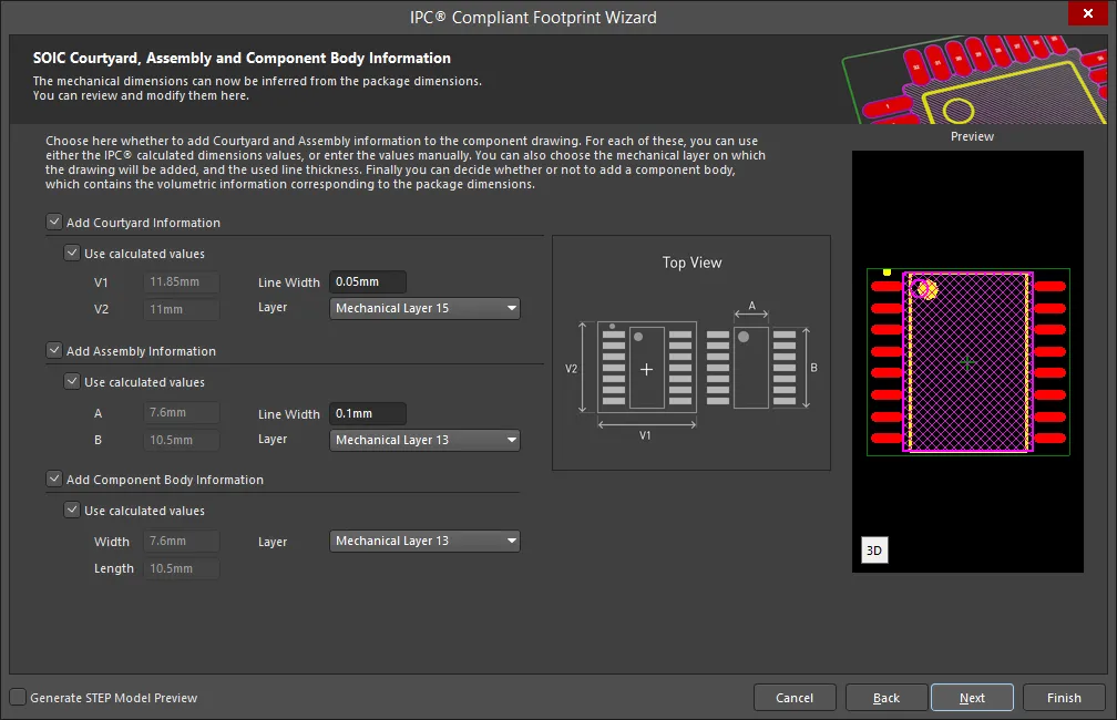
The SOIC Courtyard, Assembly and Component Body Information page displays the inferred mechanical dimensions using the package dimensions previously defined.
Enable Add Courtyard Information and Add Assembly Information to add courtyard and assembly information to the component drawing. For each, you can use the IPC calculated dimensions or enter new values directly in the textboxes. If desired, enter a new Line Width directly in the textbox. You can also select the mechanical layer for courtyard and assembly by using the drop-down next to Layer and selecting the desired mechanical layer.
A component body contains the volumetric information corresponding to the package dimensions. Enable Add Component Body Information to include this information. Enable Use calculated values to use the values displayed or disable the option and enter new desired values. You can also select the mechanical layer for the component body by using the drop-down next to Layer and selecting the desired mechanical layer.
SOJ
Copy Link
Copied
SOJ
SOJ Package Dimensions

Use the SOJ Package Dimensions page to enter the required package values for Overall Dimensions and Pin Information.
SOJ Package Heel Spacing
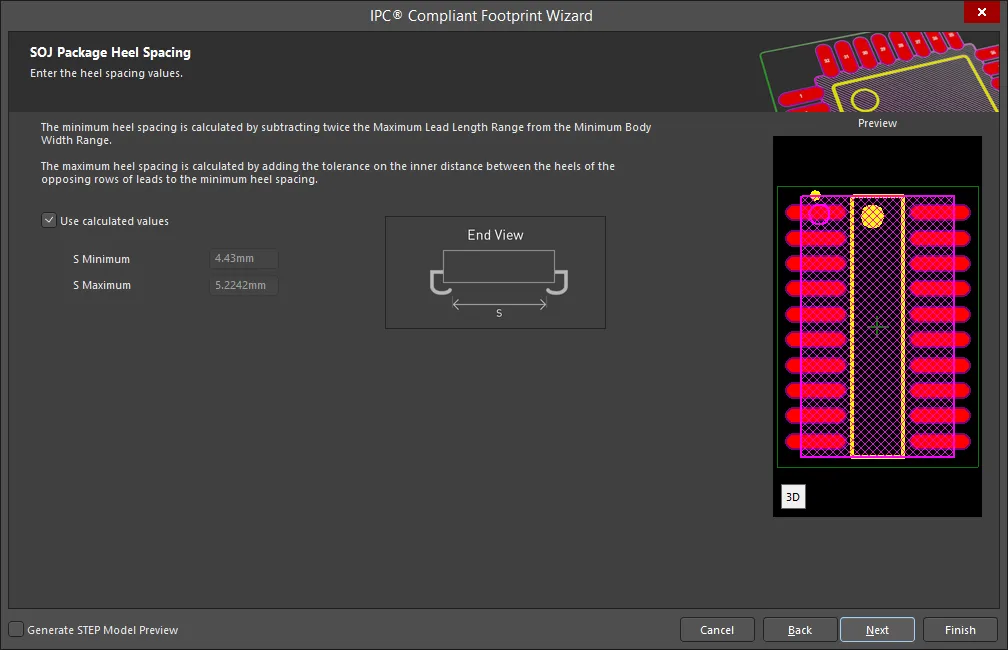
Set the desired heel spacing values on the SOJ Package Heel Spacing page.
Enable the Use calculated values checkbox to use the values currently displayed or enter new values directly in the textboxes for S Minimum and S Maximum.
SOJ Solder Fillets

Set the required solder fillet values on the SOJ Solder Fillets page. Solder fillet refers to the shape of the solder joint between the component lead and the PCB pad. Adequate fillet is required to ensure both the strength and reliability of the solder joints. A solder joint may be described by three fillets: toe, heel, and side.
Minimum values for solder fillets at the toe, heel and side of the component lead have been determined by IPC based on industry empirical knowledge and reliability testing. Enable Use default values to use the values displayed or you can adjust them to suit your specific needs.
Use the Board density Level drop-down to select the desired board density. Choose from Level A - Low density, Level B - Medium density, and Level C - High density. The Preview region is dynamically updated to show your changes.
To update the values for Toe Fillet (JT Min), Heel Fillet (JH Min), and Side Fillet (JS Min), the Use default values option must be disabled. Enter the new values directly in the textboxes.
SOJ Component Tolerances

Enter the required values for component tolerances on the SOJ Component Tolerances page.
Component manufacturers usually specify the minimum and maximum value for each package dimension. Component tolerance ranges are derived by subtracting the minimum value from the maximum value. You can adjust three of these ranges.
If the displayed values are correct for your current situation, enable the Use calculated component tolerances textbox. If the tolerance values need to be adjusted, ensure Use calculated component tolerances is disabled then enter the new values directly in the textboxes next to Tolerance on the overall width of the component, including leads, Tolerance on the inner distance between the heels of the opposing rows of leads, and Tolerance on the width of the component leads.
SOJ IPC Tolerances

IPC specifies certain tolerances for a number of standardized surface-mount package types. These tolerances are assumed by the Wizard in order to calculate a corresponding PCB footprint. You can modify the tolerances related to fabrication and placement on the SOJ IPC Tolerances page. Enable Use Default Values to accept the displayed values. You can change the values for Fabrication Tolerance Assumption, Placement Tolerance Assumption, and Courtyard Excess by entering the new values directly in the textboxes.
Modifying the IPC Tolerances may result in PCB footprints that are not IPC compliant.
SOJ Footprint Dimensions
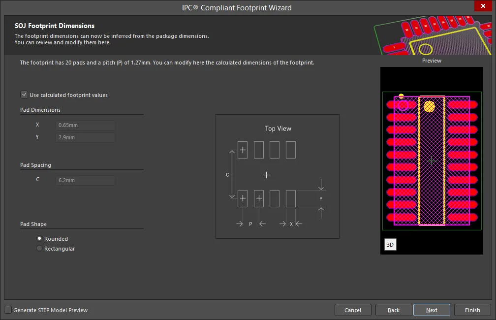
The SOJ Footprint Dimensions page displays the inferred footprint dimensions using the package dimensions previously defined. To use the displayed values, enable Use calculated footprint values or enter new values for Pad Dimensions and Pad Spacing.
Select either Rounded or Rectangular for Pad Shape.
SOJ Silkscreen Dimensions
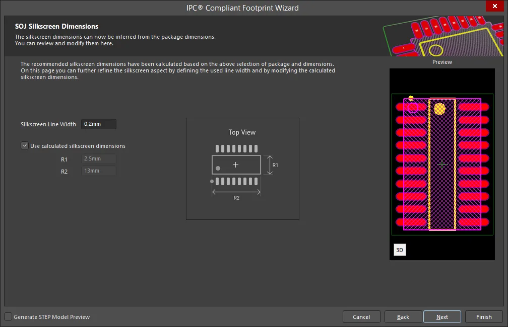
The SOJ Silkscreen Dimensions page displays the inferred silkscreen dimensions using the package dimensions previously defined. You can further define the silkscreen dimensions by entering a new value for the Silkscreen Line Width. Enable Use calculated silkscreen dimensions to use the values displayed or disable the option and enter the desired values.
SOJ Courtyard, Assembly and Component Body Information

The SOJ Courtyard, Assembly and Component Body Information page displays the inferred mechanical dimensions using the package dimensions previously defined.
Enable Add Courtyard Information and Add Assembly Information to add courtyard and assembly information to the component drawing. For each, you can use the IPC calculated dimensions or enter new values directly in the textboxes. If desired, enter a new Line Width directly in the textbox. You can also select the mechanical layer for courtyard and assembly by using the drop-down next to Layer and selecting the desired mechanical layer.
A component body contains the volumetric information corresponding to the package dimensions. Enable Add Component Body Information to include this information. Enable Use calculated values to use the values displayed or disable the option and enter new desired values. You can also select the mechanical layer for the component body by using the drop-down next to Layer and selecting the desired mechanical layer.
SON
Copy Link
Copied
SON
SON Package Dimensions
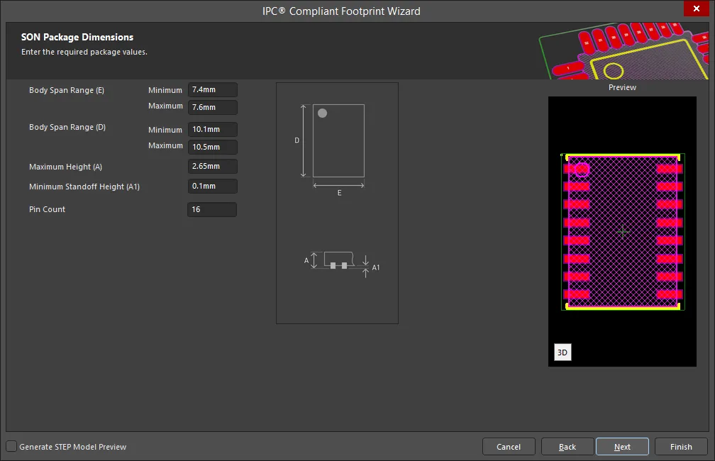
Use the SON Package Dimensions page to enter the required package values for Body Span Range(s), Maximum Height, Minimum Standoff Height, and Pin Count.
SON Package Thermal Pad Dimensions

Enter the required values for the thermal pad dimensions on the SON Package Thermal Pad Dimensions page. Enter any required changes for Lead Width Range, Lead Length Range, Pitch, Thermal Pad Ranges (s), and Lead Height.
SON Package Heel Spacing

Set the desired heel spacing values on the SON Package Heel Spacing page.
Enable the Use calculated values checkbox to use the values currently displayed or enter new values directly in the textboxes for Minimum and Maximum.
SON Solder Fillets
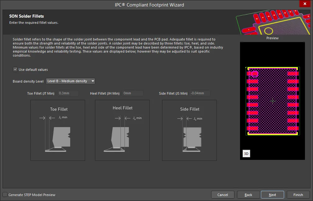
Set the required solder fillet values on the SON Solder Fillets page. Solder fillet refers to the shape of the solder joint between the component lead and the PCB pad. Adequate fillet is required to ensure both the strength and reliability of the solder joints. A solder joint may be described by three fillets: toe, heel, and side.
Minimum values for solder fillets at the toe, heel and side of the component lead have been determined by IPC based on industry empirical knowledge and reliability testing. Enable Use default values to use the values displayed or you can adjust them to suit your specific needs.
Use the Board density Level drop-down to select the desired board density. Choose from Level A - Low density, Level B - Medium density, and Level C - High density. The Preview region is dynamically updated to show your changes.
To update the values for Toe Fillet (JT Min), Heel Fillet (JH Min), and Side Fillet (JS Min), the Use default values option must be disabled. Enter the new values directly in the textboxes.
SON Component Tolerances
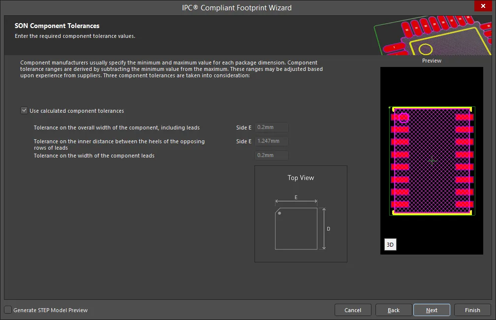
Enter the required values for component tolerances on the SON Component Tolerances page.
Component manufacturers usually specify the minimum and maximum value for each package dimension. Component tolerance ranges are derived by subtracting the minimum value from the maximum value. You can adjust three of these ranges.
If the displayed values are correct for your current situation, enable the Use calculated component tolerances textbox. If the tolerance values need to be adjusted, ensure Use calculated component tolerances is disabled then enter the new values directly in the textboxes next to Tolerance on the overall width of the component, including leads, Tolerance on the inner distance between the heels of the opposing rows of leads, and Tolerance on the width of the component leads.
SON IPC Tolerances
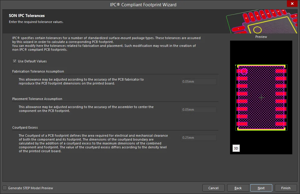
IPC specifies certain tolerances for a number of standardized surface-mount package types. These tolerances are assumed by the Wizard in order to calculate a corresponding PCB footprint. You can modify the tolerances related to fabrication and placement on the SON IPC Tolerances page. Enable Use Default Values to accept the displayed values. You can change the values for Fabrication Tolerance Assumption, Placement Tolerance Assumption, and Courtyard Excess by entering the new values directly in the textboxes.
Modifying the IPC Tolerances may result in PCB footprints that are not IPC compliant.
SON Footprint Dimensions
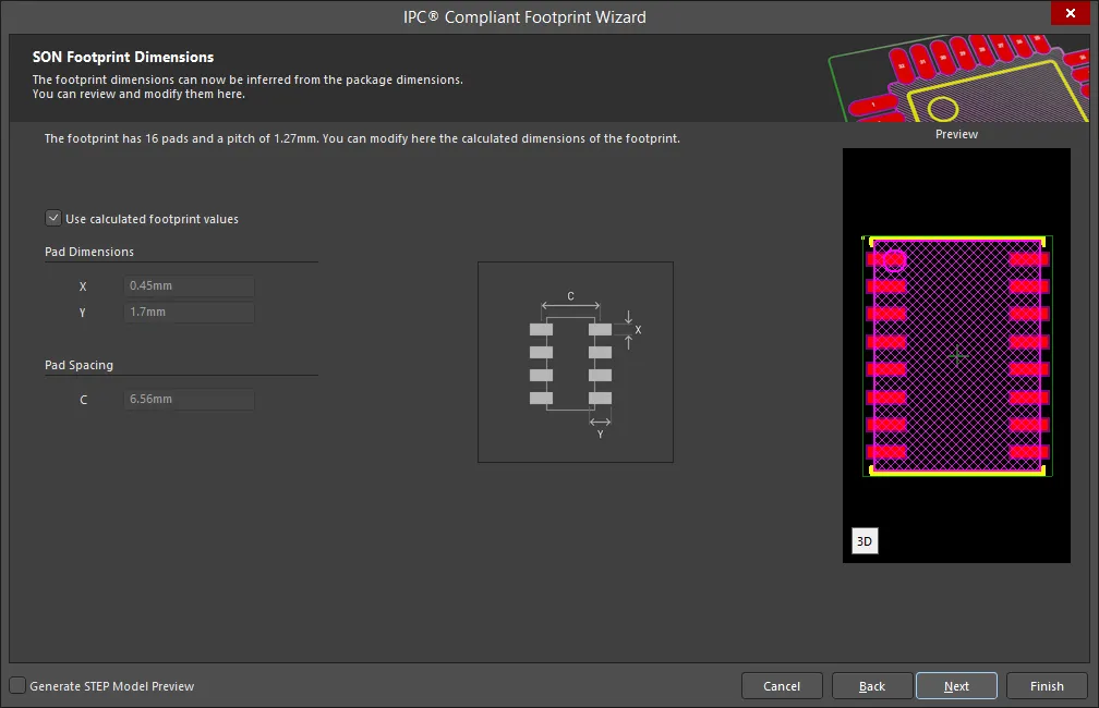
The SON Footprint Dimensions page displays the inferred footprint dimensions using the package dimensions previously defined. To use the displayed values, enable Use calculated footprint values or enter new values for Pad Dimensions and Pad Spacing.
SON Footprint Paste Fill Dimensions
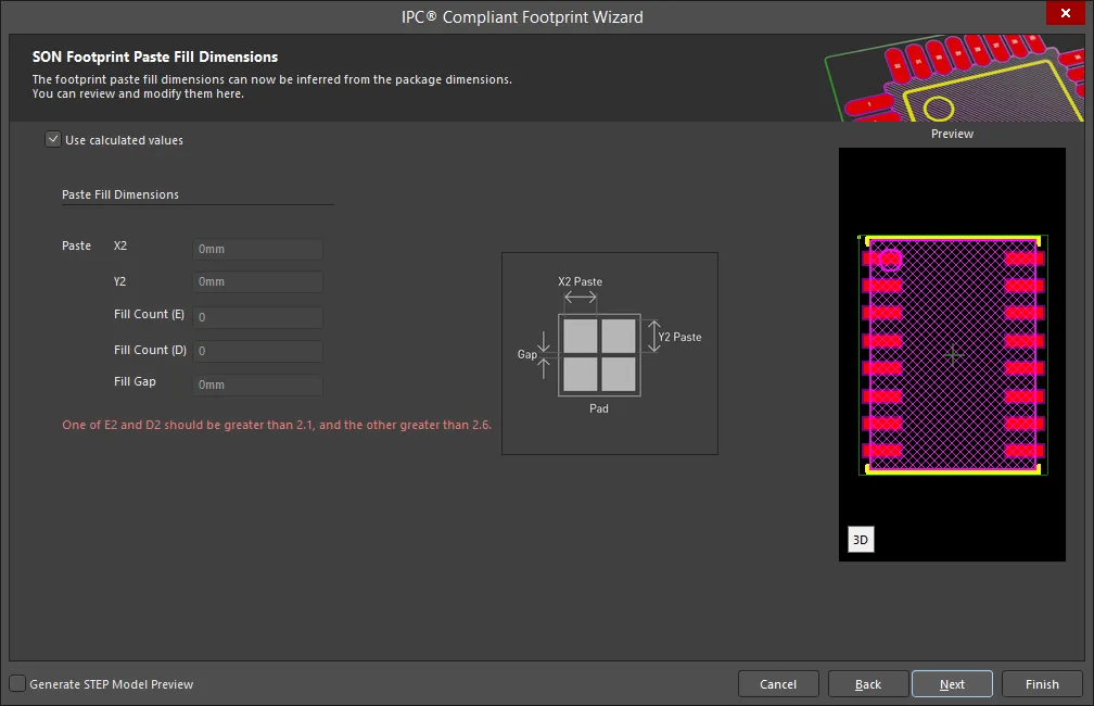
The SON Footprint Paste Fill Dimensions page displays the inferred footprint paste fill dimensions using the package dimensions previously defined. To use the displayed values, enable Use calculated footprint values or disable and enter new values for Paste Fill Dimensions.
SON Silkscreen Dimensions
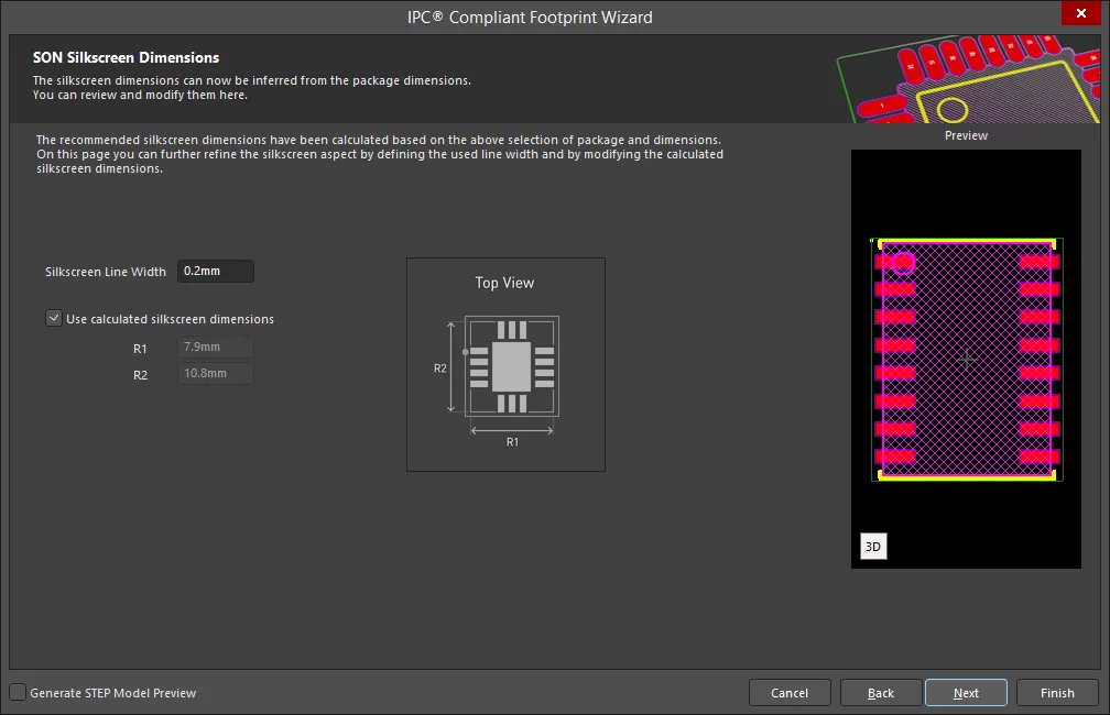
The SON Silkscreen Dimensions page displays the inferred silkscreen dimensions using the package dimensions previously defined. You can further define the silkscreen dimensions by entering a new value for the Silkscreen Line Width. Enable Use calculated silkscreen dimensions to use the values displayed or disable the option and enter the desired values.
SON Courtyard, Assembly and Component Body Information
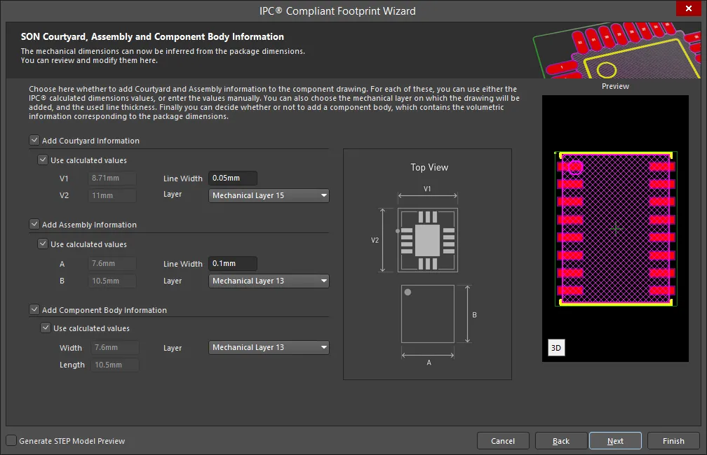
The SON Courtyard, Assembly and Component Body Information page displays the inferred mechanical dimensions using the package dimensions previously defined.
Enable Add Courtyard Information and Add Assembly Information to add courtyard and assembly information to the component drawing. For each, you can use the IPC calculated dimensions or enter new values directly in the textboxes. If desired, enter a new Line Width directly in the textbox. You can also select the mechanical layer for courtyard and assembly by using the drop-down next to Layer and selecting the desired mechanical layer.
A component body contains the volumetric information corresponding to the package dimensions. Enable Add Component Body Information to include this information. Enable Use calculated values to use the values displayed or disable the option and enter new desired values. You can also select the mechanical layer for the component body by using the drop-down next to Layer and selecting the desired mechanical layer.
SOP/TSOP
Copy Link
Copied
SOP/TSOP
SOP/TSOP Package Dimensions
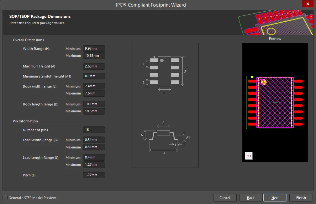
Use the SOP/TSOP Package Dimensions page to enter values for Overall Dimensions and Pin Information.
SOP/TSOP Package Thermal Pad Dimensions
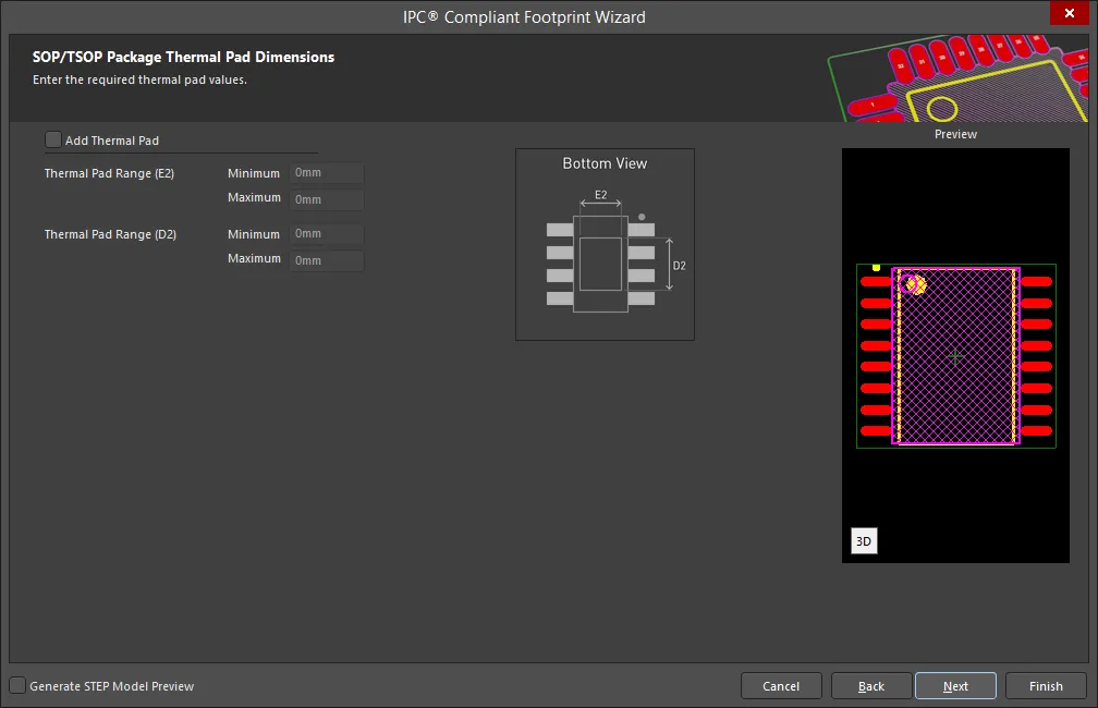
Enter the required values for the thermal pad dimensions on the SOP/TSOP Package Thermal Pad Dimensions page. Enable Add Thermal Pad if required then enter any desired changes in Thermal Pad Range(s).
SOP/TSOP Package Heel Spacing
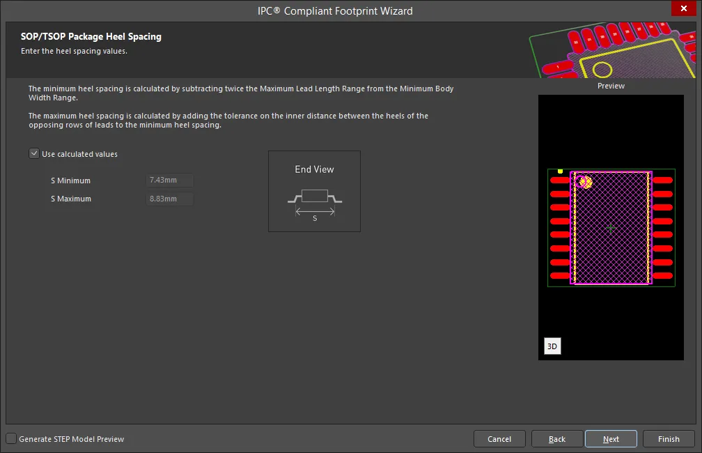
Set the desired heel spacing values on the SOP/TSOP Package Heel Spacing page.
Enable the Use calculated values checkbox to use the values currently displayed or enter new values directly in the textboxes for S Minimum and S Maximum.
SOP/TSOP Solder Fillets
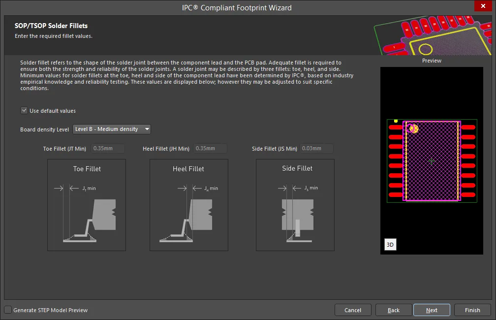
Set the required solder fillet values on the SOP/TSOP Solder Fillets page. Solder fillet refers to the shape of the solder joint between the component lead and the PCB pad. Adequate fillet is required to ensure both the strength and reliability of the solder joints. A solder joint may be described by three fillets: toe, heel, and side.
Minimum values for solder fillets at the toe, heel and side of the component lead have been determined by IPC based on industry empirical knowledge and reliability testing. Enable Use default values to use the values displayed or you can adjust them to suit your specific needs.
Use the Board density Level drop-down to select the desired board density. Choose from Level A - Low density, Level B - Medium density, and Level C - High density. The Preview region is dynamically updated to show your changes.
To update the values for Toe Fillet (JT Min), Heel Fillet (JH Min), and Side Fillet (JS Min), the Use default values option must be disabled. Enter the new values directly in the textboxes.
SOP/TSOP Component Tolerances

Enter the required values for component tolerances on the SOP/TSOP Component Tolerances page.
Component manufacturers usually specify the minimum and maximum value for each package dimension. Component tolerance ranges are derived by subtracting the minimum value from the maximum value. You can adjust three of these ranges.
If the displayed values are correct for your current situation, enable the Use calculated component tolerances textbox. If the tolerance values need to be adjusted, ensure Use calculated component tolerances is disabled then enter the new values directly in the textboxes next to Tolerance on the overall width of the component, including leads, Tolerance on the inner distance between the heels of the opposing rows of leads, and Tolerance on the width of the component leads.
SOP/TSOP IPC Tolerances

IPC specifies certain tolerances for a number of standardized surface-mount package types. These tolerances are assumed by the Wizard in order to calculate a corresponding PCB footprint. You can modify the tolerances related to fabrication and placement on the SOP/TSOP IPC Tolerances page. Enable Use Default Values to accept the displayed values. You can change the values for Fabrication Tolerance Assumption, Placement Tolerance Assumption, and Courtyard Excess by entering the new values directly in the textboxes.
Modifying the IPC Tolerances may result in PCB footprints that are not IPC compliant.
SOP/TSOP Footprint Dimensions
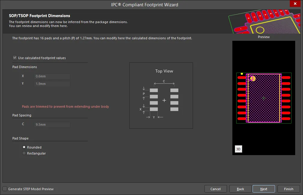
The SOP/TSOP Footprint Dimensions page displays the inferred footprint dimensions using the package dimensions previously defined. To use the displayed values, enable Use calculated footprint values or enter new values for Pad Dimensions and Pad Spacing.
Select either Rounded or Rectangular for Pad Shape.
SOP/TSOP Silkscreen Dimensions

The SOP/TSOP Silkscreen Dimensions page displays the inferred silkscreen dimensions using the package dimensions previously defined. You can further define the silkscreen dimensions by entering a new value for the Silkscreen Line Width. Enable Use calculated silkscreen dimensions to use the values displayed or disable the option and enter the desired values.
SOP/TSOP Courtyard, Assembly and Component Body Information

The SOP/TSOP Courtyard, Assembly and Component Body Information page displays the inferred mechanical dimensions using the package dimensions previously defined.
Enable Add Courtyard Information and Add Assembly Information to add courtyard and assembly information to the component drawing. For each, you can use the IPC calculated dimensions or enter new values directly in the textboxes. If desired, enter a new Line Width directly in the textbox. You can also select the mechanical layer for courtyard and assembly by using the drop-down next to Layer and selecting the desired mechanical layer.
A component body contains the volumetric information corresponding to the package dimensions. Enable Add Component Body Information to include this information. Enable Use calculated values to use the values displayed or disable the option and enter new desired values. You can also select the mechanical layer for the component body by using the drop-down next to Layer and selecting the desired mechanical layer.
SOT143/343
Copy Link
Copied
SOT143/343
SOT143/343 Package Overall Dimensions
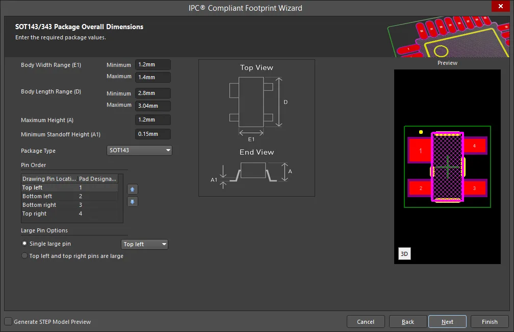
Use the SOT143/343 Package Overall Dimensions page to set the required values for Body Width Range, Body Length Range, Maximum Height, and Minimum Standoff Height. Use the drop down to select the correct Package Type: SOT143 or SOT343.
To specify the Pin Order, use  and
and  to move the selected Pad Designator up or down in the list.
Large Pin Options can be specified by selecting Single large pin or Top left and top right pins are large. If Single large pin is selected, use the drop down to specify the location: Top left, Bottom left, Bottom right, or Top right. The Preview region is dynamically updated.
SOT143/343 Package Pin Dimensions
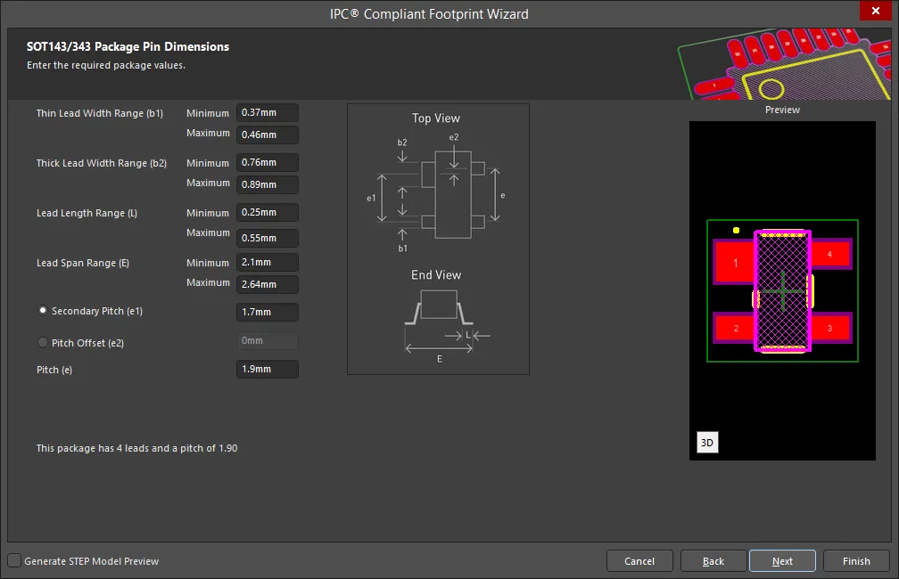
Enter the required values for the package pin dimensions on the SOT143/343 Package Pin Dimensions page.
SOT143/343 Package Heel Spacing
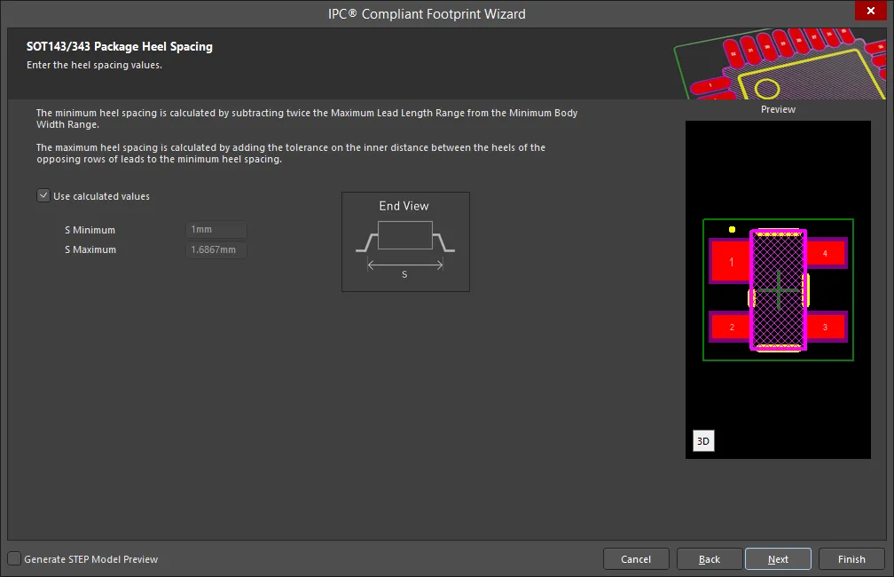
Set the desired heel spacing values on the SOT143/343 Package Heel Spacing page.
Enable the Use calculated values checkbox to use the values currently displayed or enter new values directly in the textboxes for S Minimum and S Maximum.
SOT143/343 Solder Fillets
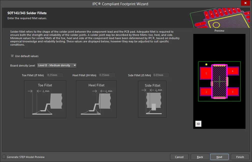
Set the required solder fillet values on the SOT143/343 Solder Fillets page. Solder fillet refers to the shape of the solder joint between the component lead and the PCB pad. Adequate fillet is required to ensure both the strength and reliability of the solder joints. A solder joint may be described by three fillets: toe, heel, and side.
Minimum values for solder fillets at the toe, heel and side of the component lead have been determined by IPC based on industry empirical knowledge and reliability testing. Enable Use default values to use the values displayed or you can adjust them to suit your specific needs.
Use the Board density Level drop-down to select the desired board density. Choose from Level A - Low density, Level B - Medium density, and Level C - High density. The Preview region is dynamically updated to show your changes.
To update the values for Toe Fillet (JT Min), Heel Fillet (JH Min), and Side Fillet (JS Min), the Use default values option must be disabled. Enter the new values directly in the textboxes.
SOT143/343 Component Tolerances
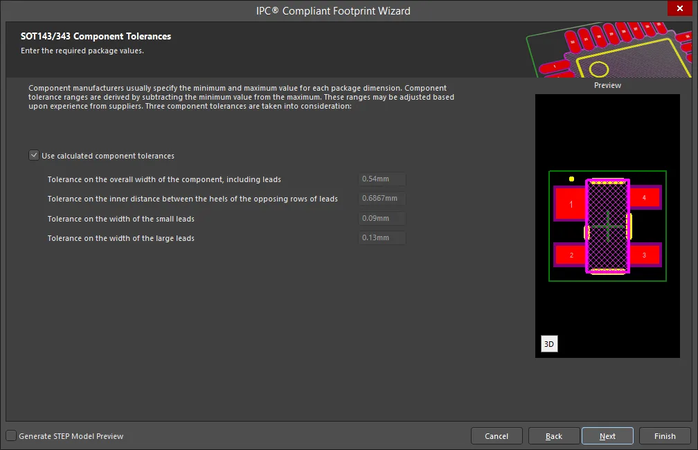
Enter the required values for component tolerances on the SOT143/343 Component Tolerances page.
Component manufacturers usually specify the minimum and maximum value for each package dimension. Component tolerance ranges are derived by subtracting the minimum value from the maximum value. You can adjust three of these ranges.
If the displayed values are correct for your current situation, enable the Use calculated component tolerances textbox. If the tolerance values need to be adjusted, ensure Use calculated component tolerances is disabled then enter the new values directly in the textboxes next to Tolerance on the overall width of the component, including leads, Tolerance on the inner distance between the heels of the opposing rows of leads, and Tolerance on the width of the component leads.
SOT143/343 IPC Tolerances
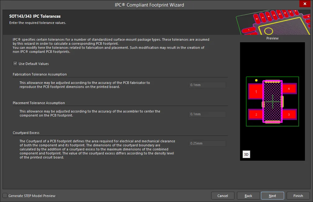
IPC specifies certain tolerances for a number of standardized surface-mount package types. These tolerances are assumed by the Wizard in order to calculate a corresponding PCB footprint. You can modify the tolerances related to fabrication and placement on the SOT143/343 IPC Tolerances page. Enable Use Default Values to accept the displayed values. You can change the values for Fabrication Tolerance Assumption, Placement Tolerance Assumption, and Courtyard Excess by entering the new values directly in the textboxes.
Modifying the IPC Tolerances may result in PCB footprints that are not IPC compliant.
SOT143/343 Footprint Dimensions
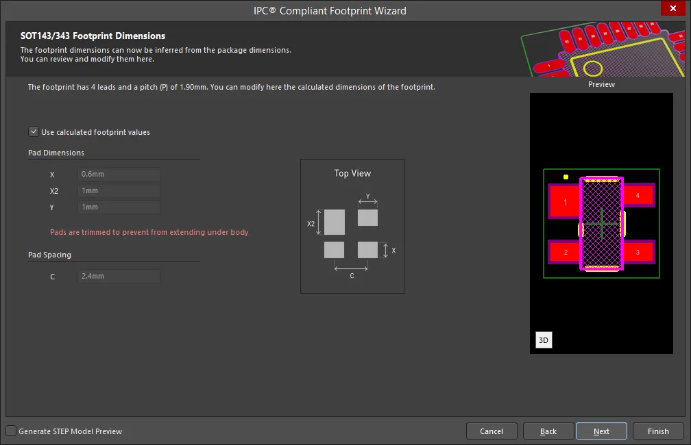
The SOT143/343 Footprint Dimensions page displays the inferred footprint dimensions using the package dimensions previously defined. To use the displayed values, enable Use calculated footprint values or enter new values for Pad Dimensions and Pad Spacing.
SOT143/343 Silkscreen Dimensions
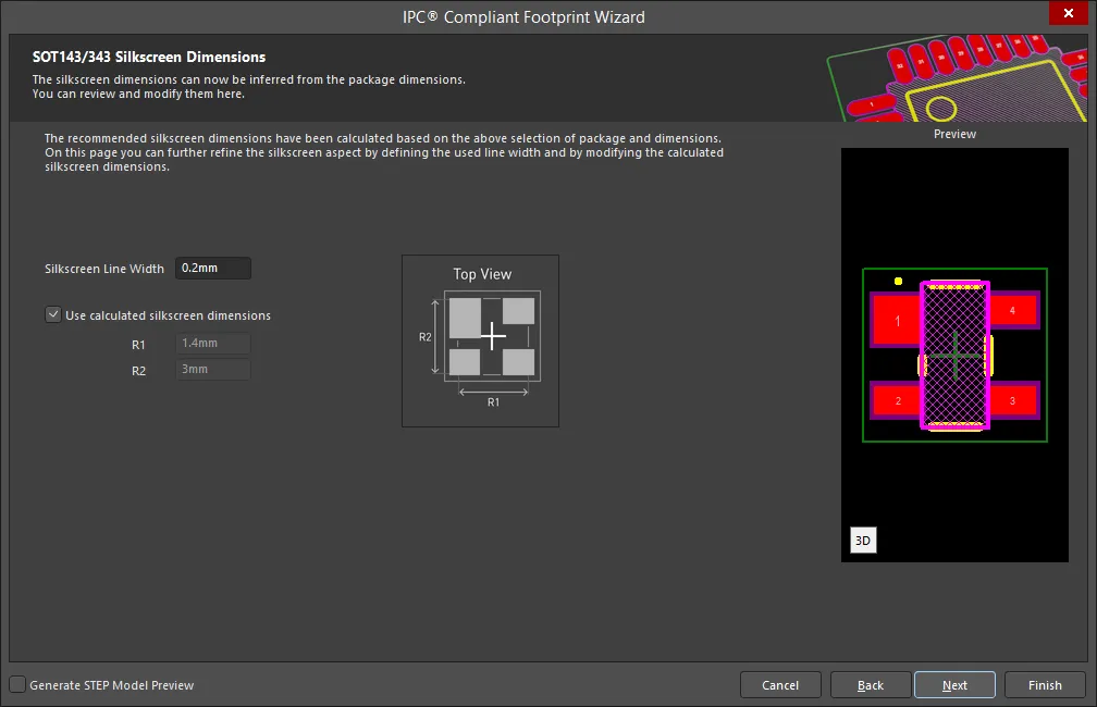
The SOT143/343 Silkscreen Dimensions page displays the inferred silkscreen dimensions using the package dimensions previously defined. You can further define the silkscreen dimensions by entering a new value for the Silkscreen Line Width. Enable Use calculated silkscreen dimensions to use the values displayed or disable the option and enter the desired values.
SOT143/343 Courtyard, Assembly and Component Body Information
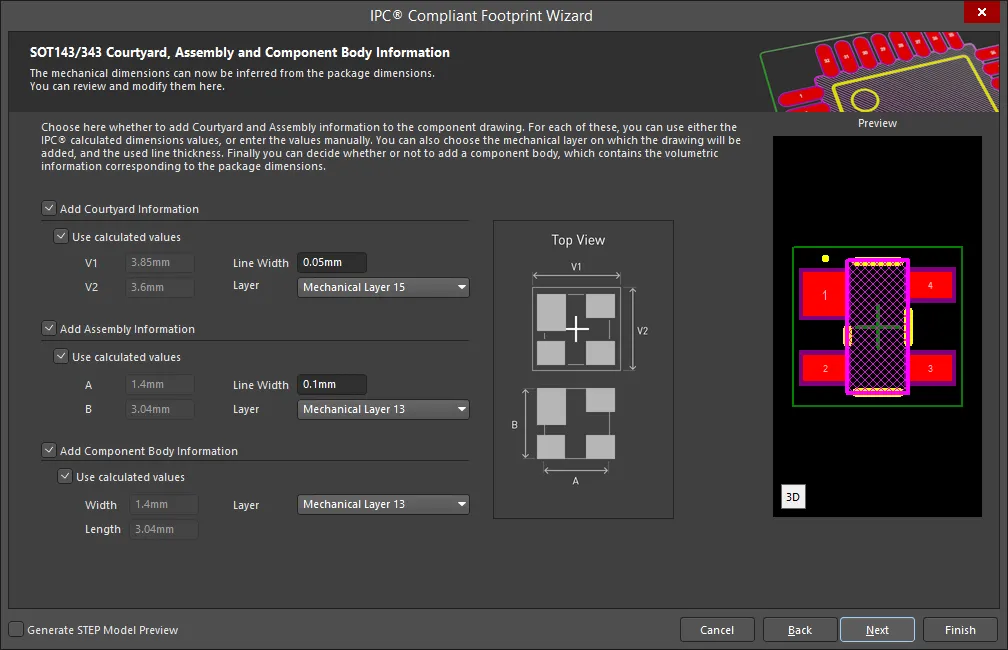
The SOT143/343 Courtyard, Assembly and Component Body Information page displays the inferred mechanical dimensions using the package dimensions previously defined.
Enable Add Courtyard Information and Add Assembly Information to add courtyard and assembly information to the component drawing. For each, you can use the IPC calculated dimensions or enter new values directly in the textboxes. If desired, enter a new Line Width directly in the textbox. You can also select the mechanical layer for courtyard and assembly by using the drop-down next to Layer and selecting the desired mechanical layer.
A component body contains the volumetric information corresponding to the package dimensions. Enable Add Component Body Information to include this information. Enable Use calculated values to use the values displayed or disable the option and enter new desired values. You can also select the mechanical layer for the component body by using the drop-down next to Layer and selecting the desired mechanical layer.
SOT223
Copy Link
Copied
SOT223
SOT223 Package Overall Dimensions
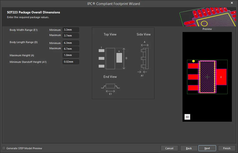
Use the SOT223 Package Overall Dimensions page to set the required values for Body Width Range, Body Length Range, Maximum Height, and Minimum Standoff Height.
SOT223 Package Pin Dimensions
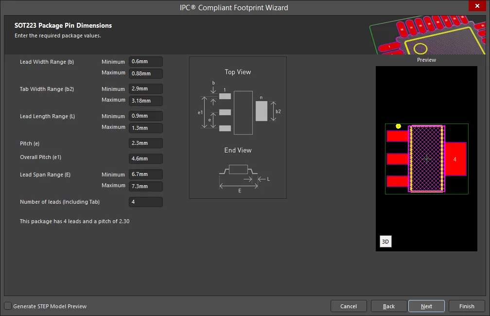
Enter the required values for the package pin dimensions on the SOT223 Package Pin Dimensions page.
SOT223 Package Heel Spacing
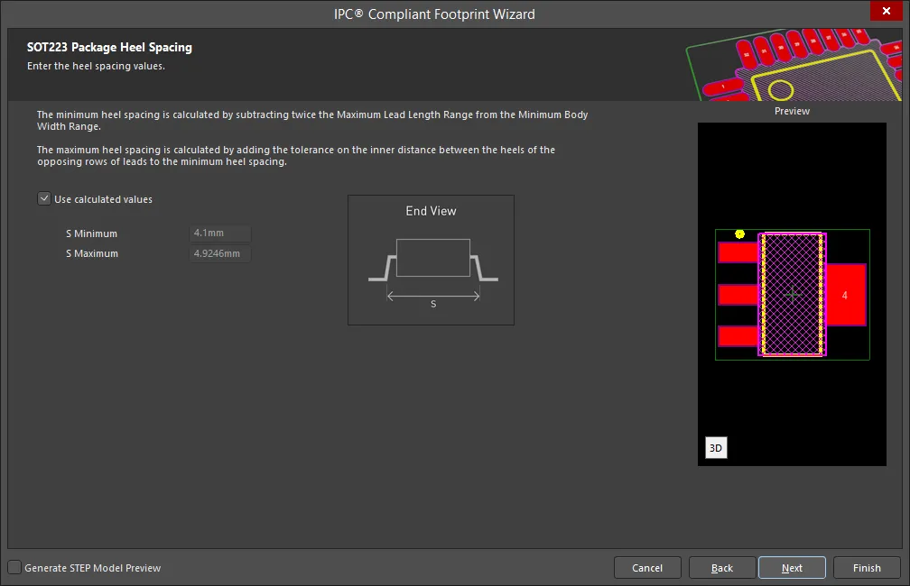
Set the desired heel spacing values on the SOT223 Package Heel Spacing page.
Enable the Use calculated values checkbox to use the values currently displayed or enter new values directly in the textboxes for S Minimum and S Maximum.
SOT223 Solder Fillets
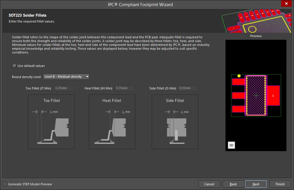
Set the required solder fillet values on the SOT223 Solder Fillets page. Solder fillet refers to the shape of the solder joint between the component lead and the PCB pad. Adequate fillet is required to ensure both the strength and reliability of the solder joints. A solder joint may be described by three fillets: toe, heel, and side.
Minimum values for solder fillets at the toe, heel and side of the component lead have been determined by IPC based on industry empirical knowledge and reliability testing. Enable Use default values to use the values displayed or you can adjust them to suit your specific needs.
Use the Board density Level drop-down to select the desired board density. Choose from Level A - Low density, Level B - Medium density, and Level C - High density. The Preview region is dynamically updated to show your changes.
To update the values for Toe Fillet (JT Min), Heel Fillet (JH Min), and Side Fillet (JS Min), the Use default values option must be disabled. Enter the new values directly in the textboxes.
SOT223 Component Tolerances
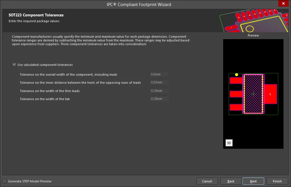
Enter the required values for component tolerances on the SOT223 Component Tolerances page.
Component manufacturers usually specify the minimum and maximum value for each package dimension. Component tolerance ranges are derived by subtracting the minimum value from the maximum value. You can adjust three of these ranges.
If the displayed values are correct for your current situation, enable the Use calculated component tolerances textbox. If the tolerance values need to be adjusted, ensure Use calculated component tolerances is disabled then enter the new values directly in the textboxes next to Tolerance on the overall width of the component, including leads, Tolerance on the inner distance between the heels of the opposing rows of leads, and Tolerance on the width of the component leads.
SOT223 IPC Tolerances
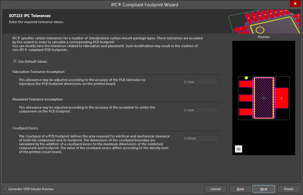
IPC specifies certain tolerances for a number of standardized surface-mount package types. These tolerances are assumed by the Wizard in order to calculate a corresponding PCB footprint. You can modify the tolerances related to fabrication and placement on the SOT223 IPC Tolerances page. Enable Use Default Values to accept the displayed values. You can change the values for Fabrication Tolerance Assumption, Placement Tolerance Assumption, and Courtyard Excess by entering the new values directly in the textboxes.
Modifying the IPC Tolerances may result in PCB footprints that are not IPC compliant.
SOT223 Footprint Dimensions
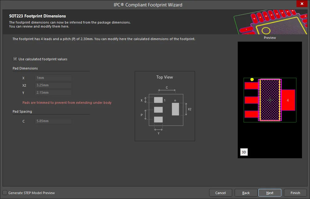
The SOT223 Footprint Dimensions page displays the inferred footprint dimensions using the package dimensions previously defined. To use the displayed values, enable Use calculated footprint values or enter new values for Pad Dimensions and Pad Spacing.
SOT223 Silkscreen Dimensions
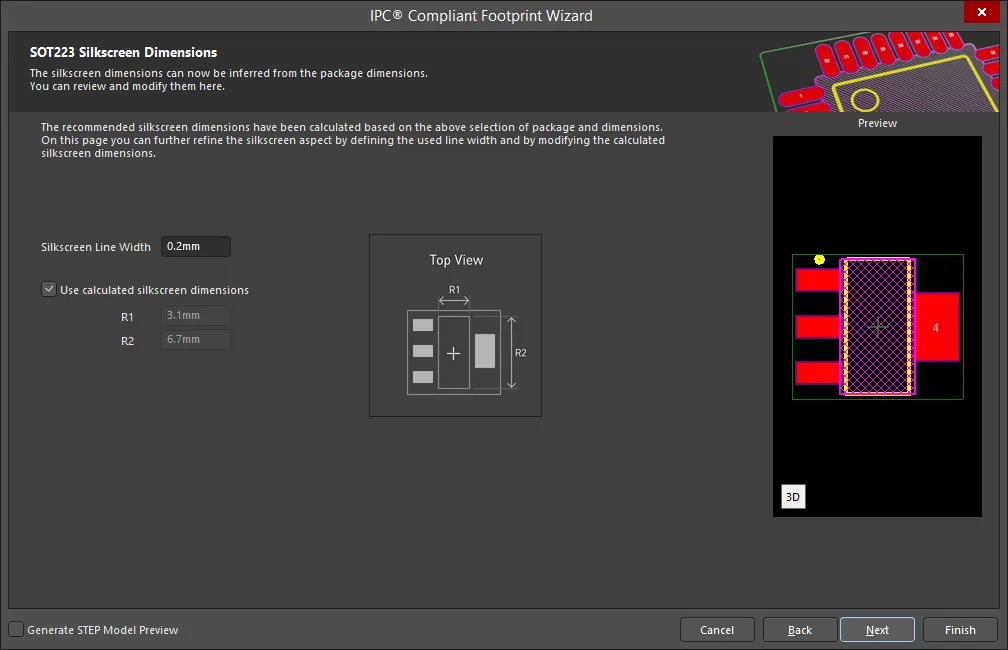
The SOT223 Silkscreen Dimensions page displays the inferred silkscreen dimensions using the package dimensions previously defined. You can further define the silkscreen dimensions by entering a new value for the Silkscreen Line Width. Enable Use calculated silkscreen dimensions to use the values displayed or disable the option and enter the desired values.
SOT223 Courtyard, Assembly and Component Body Information
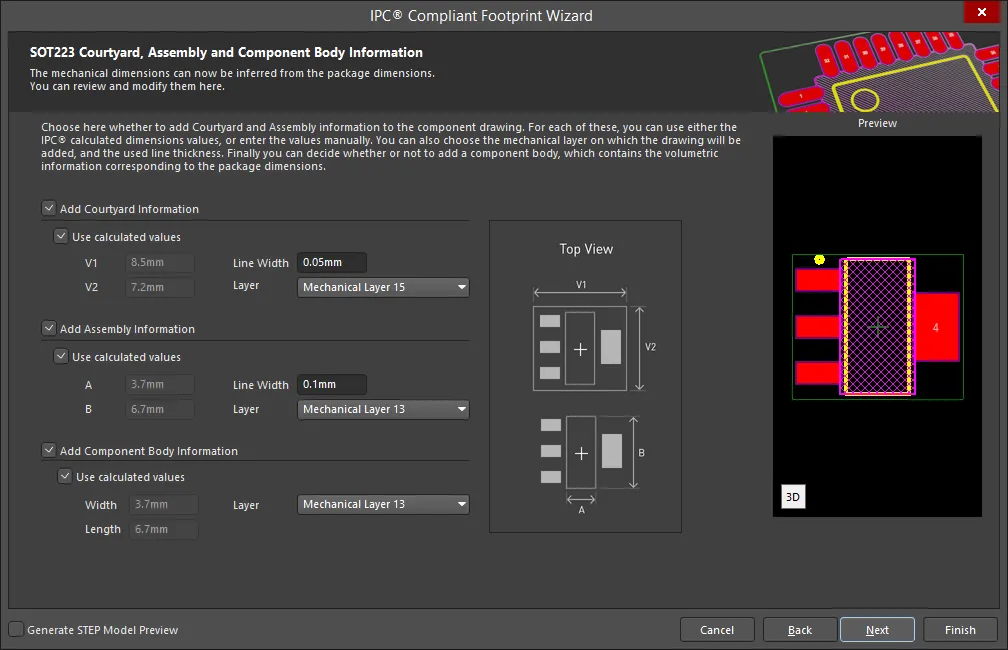
The SOT223 Courtyard, Assembly and Component Body Information page displays the inferred mechanical dimensions using the package dimensions previously defined.
Enable Add Courtyard Information and Add Assembly Information to add courtyard and assembly information to the component drawing. For each, you can use the IPC calculated dimensions or enter new values directly in the textboxes. If desired, enter a new Line Width directly in the textbox. You can also select the mechanical layer for courtyard and assembly by using the drop-down next to Layer and selecting the desired mechanical layer.
A component body contains the volumetric information corresponding to the package dimensions. Enable Add Component Body Information to include this information. Enable Use calculated values to use the values displayed or disable the option and enter new desired values. You can also select the mechanical layer for the component body by using the drop-down next to Layer and selecting the desired mechanical layer.
SOT23
Copy Link
Copied
SOT23
SOT23 Package Overall Dimensions
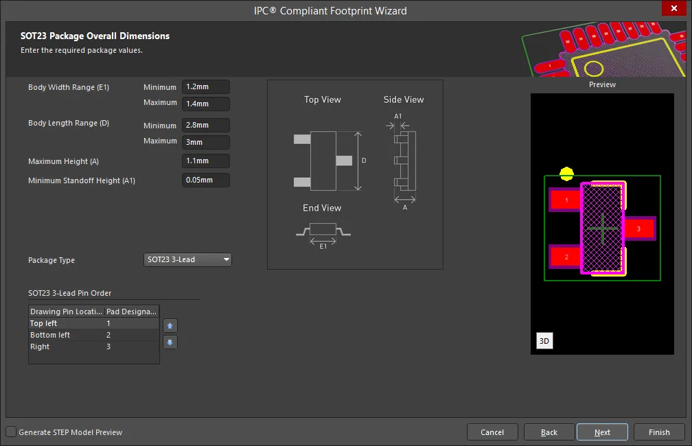
Use the SOT23 Package Overall Dimensions page to set the required values for Body Width Range, Body Length Range, Maximum Height, and Minimum Standoff Height. Use the drop down to select the correct Package Type: SOT23 3-Lead, SOT23 5-Lead, or SOT23 6-Lead.
To specify the Pin Order, use  and
and  to move the selected Pad Designator up or down in the list.
SOT23 Package Pin Dimensions
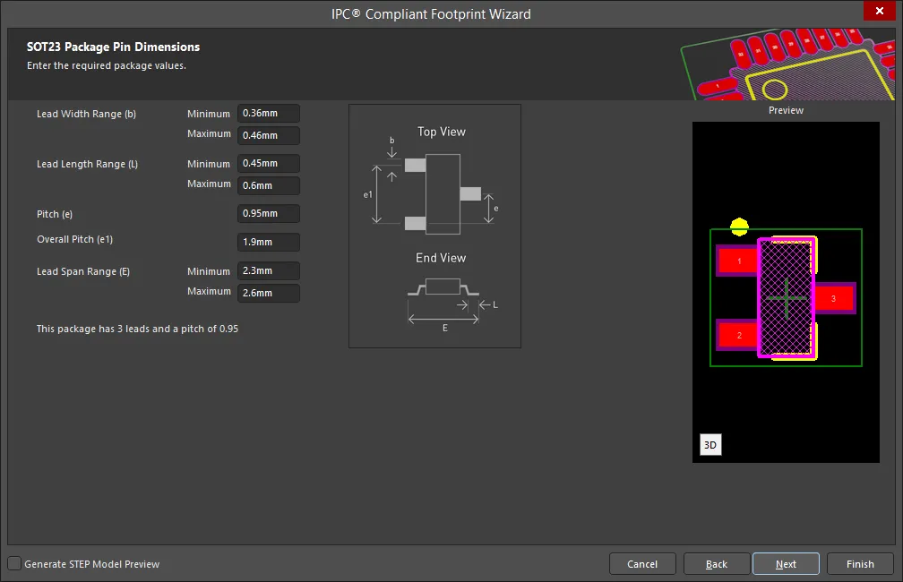
Enter the required values for the package pin dimensions on the SOT23 Package Pin Dimensions page.
SOT23 Package Heel Spacing

Set the desired heel spacing values on the SOT23 Package Heel Spacing page.
Enable the Use calculated values checkbox to use the values currently displayed or enter new values directly in the textboxes for S Minimum and S Maximum.
SOT23 Package Round Off
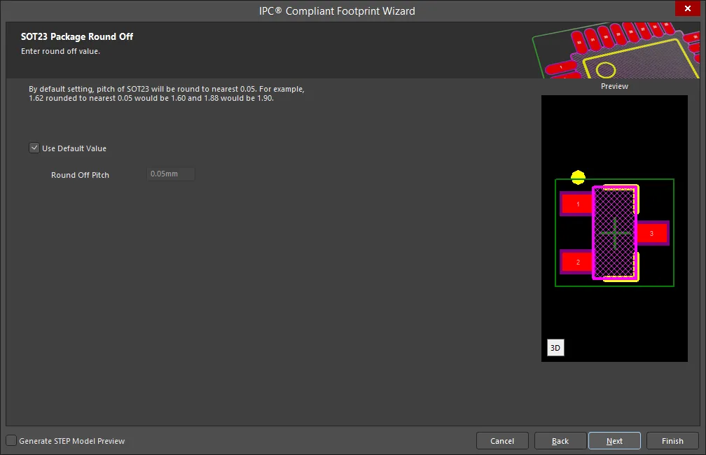
Use the SOT23 Package Round Off page to set the round off value. Enable Use Calculated Value to use the value currently displayed or enter a new value directly in the textbox for Round Off Pitch.
SOT23 Solder Fillets

Set the required solder fillet values on the SOT23 Solder Fillets page. Solder fillet refers to the shape of the solder joint between the component lead and the PCB pad. Adequate fillet is required to ensure both the strength and reliability of the solder joints. A solder joint may be described by three fillets: toe, heel, and side.
Minimum values for solder fillets at the toe, heel and side of the component lead have been determined by IPC based on industry empirical knowledge and reliability testing. Enable Use default values to use the values displayed or you can adjust them to suit your specific needs.
Use the Board density Level drop-down to select the desired board density. Choose from Level A - Low density, Level B - Medium density, and Level C - High density. The Preview region is dynamically updated to show your changes.
To update the values for Toe Fillet (JT Min), Heel Fillet (JH Min), and Side Fillet (JS Min), the Use default values option must be disabled. Enter the new values directly in the textboxes.
SOT23 Component Tolerances

Enter the required values for component tolerances on the SOT23 Component Tolerances page.
Component manufacturers usually specify the minimum and maximum value for each package dimension. Component tolerance ranges are derived by subtracting the minimum value from the maximum value. You can adjust three of these ranges.
If the displayed values are correct for your current situation, enable the Use calculated component tolerances textbox. If the tolerance values need to be adjusted, ensure Use calculated component tolerances is disabled then enter the new values directly in the textboxes next to Tolerance on the overall width of the component, including leads, Tolerance on the inner distance between the heels of the opposing rows of leads, and Tolerance on the width of the component leads.
SOT23 IPC Tolerances
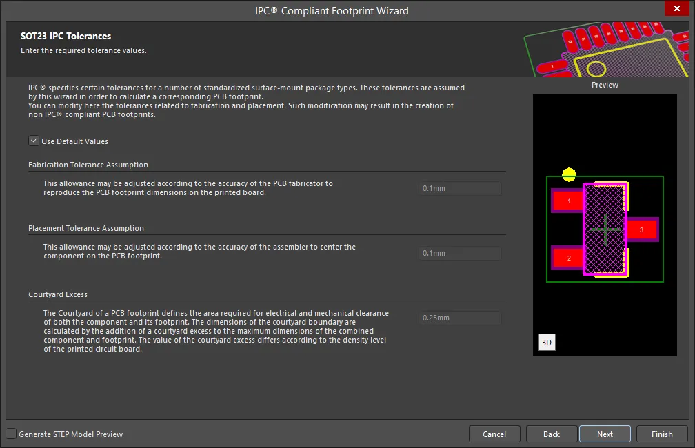
IPC specifies certain tolerances for a number of standardized surface-mount package types. These tolerances are assumed by the Wizard in order to calculate a corresponding PCB footprint. You can modify the tolerances related to fabrication and placement on the SOT23 IPC Tolerances page. Enable Use Default Values to accept the displayed values. You can change the values for Fabrication Tolerance Assumption, Placement Tolerance Assumption, and Courtyard Excess by entering the new values directly in the textboxes.
Modifying the IPC Tolerances may result in PCB footprints that are not IPC compliant.
SOT23 Footprint Dimensions
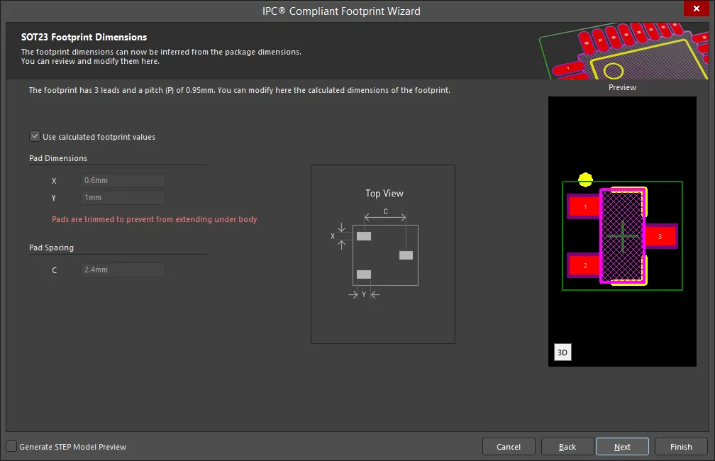
The SOT23 Footprint Dimensions page displays the inferred footprint dimensions using the package dimensions previously defined. To use the displayed values, enable Use calculated footprint values or enter new values for Pad Dimensions and Pad Spacing.
SOT23 Silkscreen Dimensions
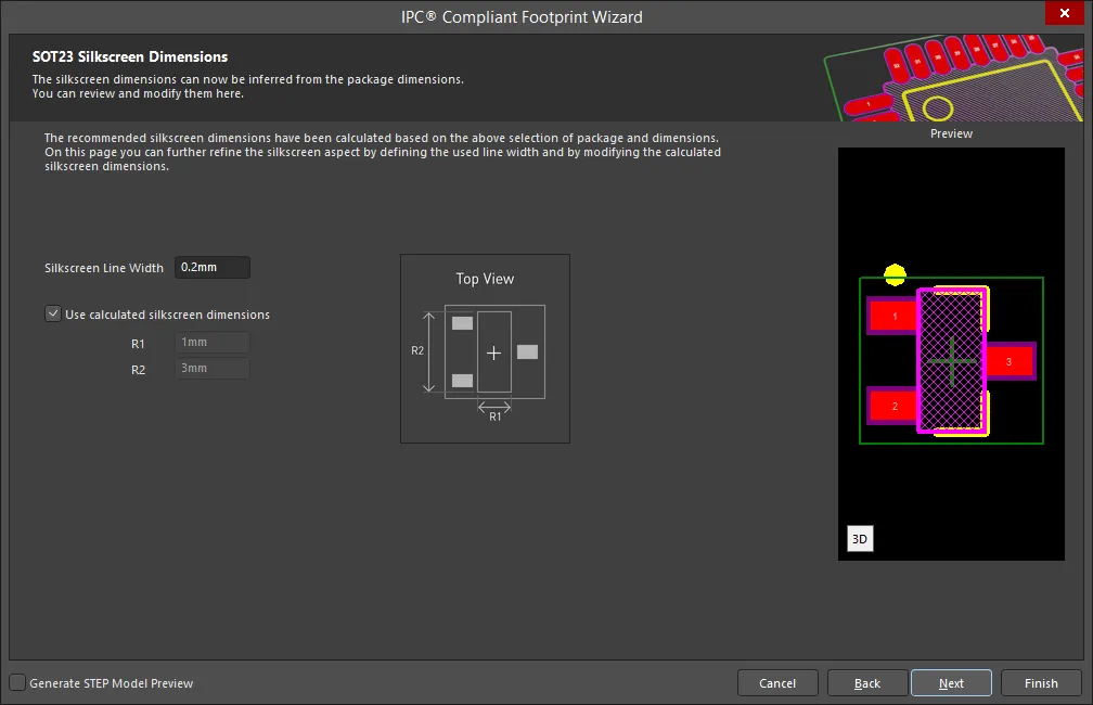
The SOT23 Silkscreen Dimensions page displays the inferred silkscreen dimensions using the package dimensions previously defined. You can further define the silkscreen dimensions by entering a new value for the Silkscreen Line Width. Enable Use calculated silkscreen dimensions to use the values displayed or disable the option and enter the desired values.
SOT23 Courtyard, Assembly and Component Body Information

The SOT23 Courtyard, Assembly and Component Body Information page displays the inferred mechanical dimensions using the package dimensions previously defined.
Enable Add Courtyard Information and Add Assembly Information to add courtyard and assembly information to the component drawing. For each, you can use the IPC calculated dimensions or enter new values directly in the textboxes. If desired, enter a new Line Width directly in the textbox. You can also select the mechanical layer for courtyard and assembly by using the drop-down next to Layer and selecting the desired mechanical layer.
A component body contains the volumetric information corresponding to the package dimensions. Enable Add Component Body Information to include this information. Enable Use calculated values to use the values displayed or disable the option and enter new desired values. You can also select the mechanical layer for the component body by using the drop-down next to Layer and selecting the desired mechanical layer.
SOT89
Copy Link
Copied
SOT89
SOT89 Package Overall Dimensions

Use the SOT89 Package Overall Dimensions page to set the required values for Body Width Range, Body Length Range, and Maximum Height.
Enable Reverse Pin Order to reverse the pin order. The Preview region is dynamically updated.
SOT89 Package Pin Dimensions
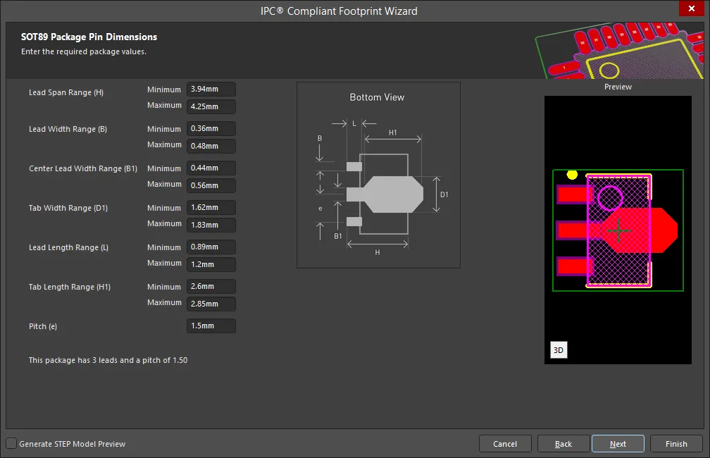
Enter the required values for the package pin dimensions on the SOT89 Package Pin Dimensions page.
SOT89 Solder Fillets
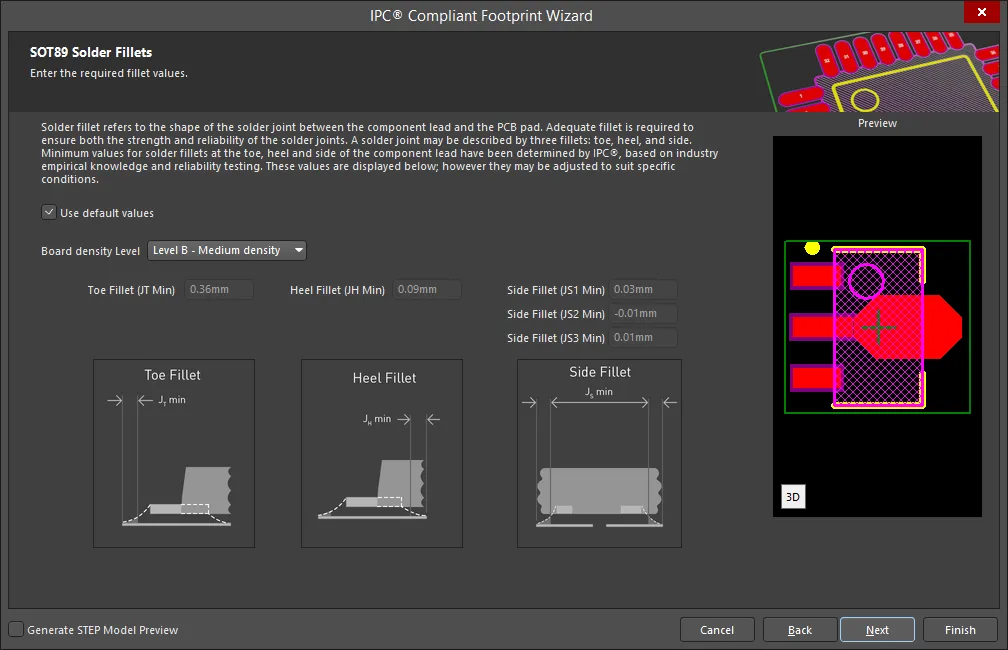
Set the required solder fillet values on the SOT89 Solder Fillets page. Solder fillet refers to the shape of the solder joint between the component lead and the PCB pad. Adequate fillet is required to ensure both the strength and reliability of the solder joints. A solder joint may be described by three fillets: toe, heel, and side.
Minimum values for solder fillets at the toe, heel and side of the component lead have been determined by IPC based on industry empirical knowledge and reliability testing. Enable Use default values to use the values displayed or you can adjust them to suit your specific needs.
Use the Board density Level drop-down to select the desired board density. Choose from Level A - Low density, Level B - Medium density, and Level C - High density. The Preview region is dynamically updated to show your changes.
To update the values for Toe Fillet (JT Min), Heel Fillet (JH Min), and Side Fillet (JS Min), the Use default values option must be disabled. Enter the new values directly in the textboxes.
SOT89 Component Tolerances
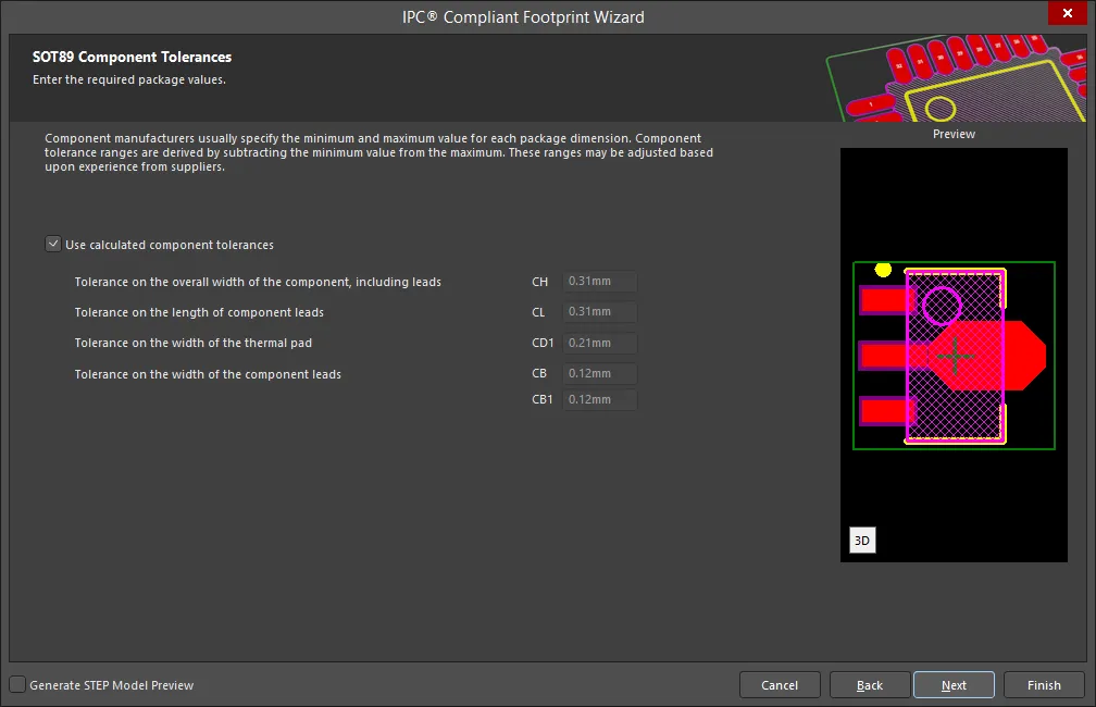
Enter the required values for component tolerances on the SOT89 Component Tolerances page.
Component manufacturers usually specify the minimum and maximum value for each package dimension. Component tolerance ranges are derived by subtracting the minimum value from the maximum value. You can adjust three of these ranges.
If the displayed values are correct for your current situation, enable the Use calculated component tolerances textbox. If the tolerance values need to be adjusted, ensure Use calculated component tolerances is disabled then enter the new values directly in the textboxes next to Tolerance on the overall width of the component, including leads, Tolerance on the inner distance between the heels of the opposing rows of leads, and Tolerance on the width of the component leads.
SOT89 IPC Tolerances
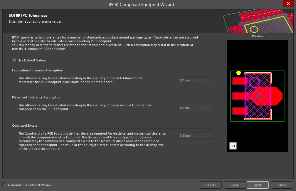
IPC specifies certain tolerances for a number of standardized surface-mount package types. These tolerances are assumed by the Wizard in order to calculate a corresponding PCB footprint. You can modify the tolerances related to fabrication and placement on the SOT89 IPC Tolerances page. Enable Use Default Values to accept the displayed values. You can change the values for Fabrication Tolerance Assumption, Placement Tolerance Assumption, and Courtyard Excess by entering the new values directly in the textboxes.
Modifying the IPC Tolerances may result in PCB footprints that are not IPC compliant.
SOT89 Footprint Dimensions
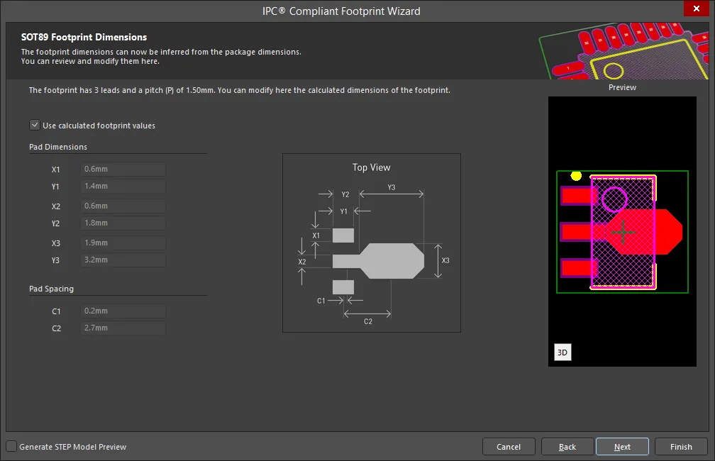
The SOT89 Footprint Dimensions page displays the inferred footprint dimensions using the package dimensions previously defined. To use the displayed values, enable Use calculated footprint values or enter new values for Pad Dimensions and Pad Spacing.
SOT89 Silkscreen Dimensions
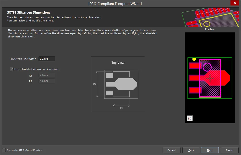
The SOT89 Silkscreen Dimensions page displays the inferred silkscreen dimensions using the package dimensions previously defined. You can further define the silkscreen dimensions by entering a new value for the Silkscreen Line Width. Enable Use calculated silkscreen dimensions to use the values displayed or disable the option and enter the desired values.
SOT89 Courtyard, Assembly and Component Body Information
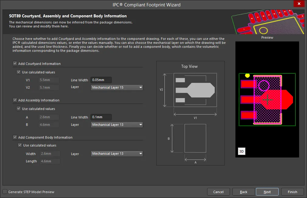
The SOT89 Courtyard, Assembly and Component Body Information page displays the inferred mechanical dimensions using the package dimensions previously defined.
Enable Add Courtyard Information and Add Assembly Information to add courtyard and assembly information to the component drawing. For each, you can use the IPC calculated dimensions or enter new values directly in the textboxes. If desired, enter a new Line Width directly in the textbox. You can also select the mechanical layer for courtyard and assembly by using the drop-down next to Layer and selecting the desired mechanical layer.
A component body contains the volumetric information corresponding to the package dimensions. Enable Add Component Body Information to include this information. Enable Use calculated values to use the values displayed or disable the option and enter new desired values. You can also select the mechanical layer for the component body by using the drop-down next to Layer and selecting the desired mechanical layer.
SOTFL
Copy Link
Copied
SOTFL
SOTFL Package Overall Dimensions
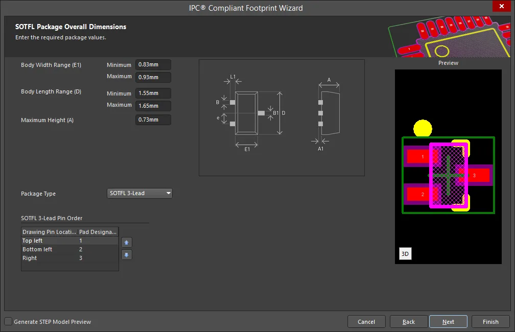
Use the SOTFL Package Overall Dimensions page to set the required values for Body Width Range, Body Length Range, and Maximum Height. Use the drop down to select the correct Package Type: SOTFL 3-Lead, SOTFL 5-Lead, or SOTFL 6-Lead.
To specify the Pin Order, use  and
and  to move the selected Pad Designator up or down in the list.
SOTFL Package Pin Dimensions

Enter the required values for the package pin dimensions on the SOTFL Package Pin Dimensions page.
SOTFL Package Heel Spacing
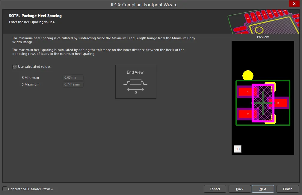
Set the desired heel spacing values on the SOTFL Package Heel Spacing page.
Enable the Use calculated values checkbox to use the values currently displayed or enter new values directly in the textboxes for S Minimum and S Maximum.
SOTFL Solder Fillets
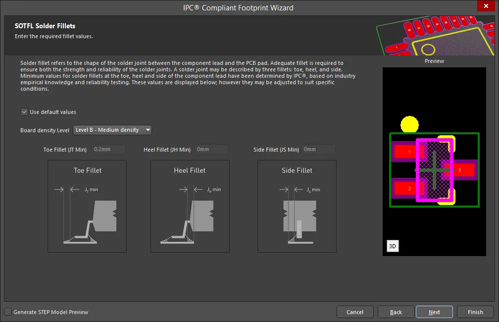
Set the required solder fillet values on the SOTFL Solder Fillets page. Solder fillet refers to the shape of the solder joint between the component lead and the PCB pad. Adequate fillet is required to ensure both the strength and reliability of the solder joints. A solder joint may be described by three fillets: toe, heel, and side.
Minimum values for solder fillets at the toe, heel and side of the component lead have been determined by IPC based on industry empirical knowledge and reliability testing. Enable Use default values to use the values displayed or you can adjust them to suit your specific needs.
Use the Board density Level drop-down to select the desired board density. Choose from Level A - Low density, Level B - Medium density, and Level C - High density. The Preview region is dynamically updated to show your changes.
To update the values for Toe Fillet (JT Min), Heel Fillet (JH Min), and Side Fillet (JS Min), the Use default values option must be disabled. Enter the new values directly in the textboxes.
SOTFL Component Tolerances

Enter the required values for component tolerances on the SOTFL Component Tolerances page.
Component manufacturers usually specify the minimum and maximum value for each package dimension. Component tolerance ranges are derived by subtracting the minimum value from the maximum value. You can adjust three of these ranges.
If the displayed values are correct for your current situation, enable the Use calculated component tolerances textbox. If the tolerance values need to be adjusted, ensure Use calculated component tolerances is disabled then enter the new values directly in the textboxes next to Tolerance on the overall width of the component, including leads, Tolerance on the inner distance between the heels of the opposing rows of leads, and Tolerance on the width of the component leads.
SOTFL IPC Tolerances
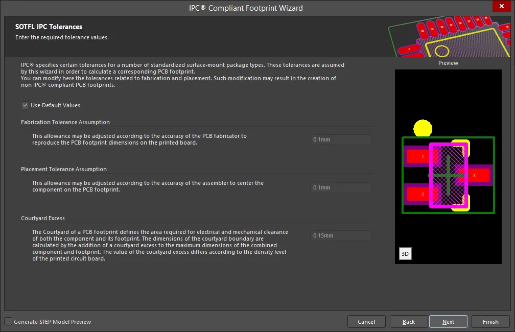
IPC specifies certain tolerances for a number of standardized surface-mount package types. These tolerances are assumed by the Wizard in order to calculate a corresponding PCB footprint. You can modify the tolerances related to fabrication and placement on the SOTFL IPC Tolerances page. Enable Use Default Values to accept the displayed values. You can change the values for Fabrication Tolerance Assumption, Placement Tolerance Assumption, and Courtyard Excess by entering the new values directly in the textboxes.
Modifying the IPC Tolerances may result in PCB footprints that are not IPC compliant.
SOTFL Footprint Dimensions
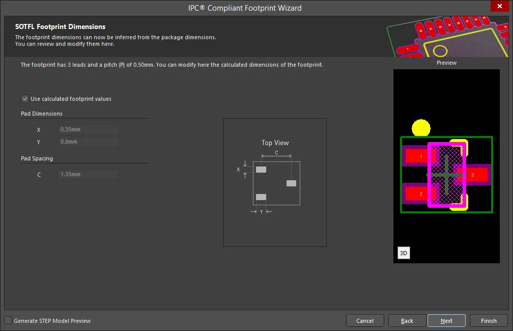
The SOTFL Footprint Dimensions page displays the inferred footprint dimensions using the package dimensions previously defined. To use the displayed values, enable Use calculated footprint values or enter new values for Pad Dimensions and Pad Spacing.
SOTFL Silkscreen Dimensions

The SOTFL Silkscreen Dimensions page displays the inferred silkscreen dimensions using the package dimensions previously defined. You can further define the silkscreen dimensions by entering a new value for the Silkscreen Line Width. Enable Use calculated silkscreen dimensions to use the values displayed or disable the option and enter the desired values.
SOTFL Courtyard, Assembly and Component Body Information
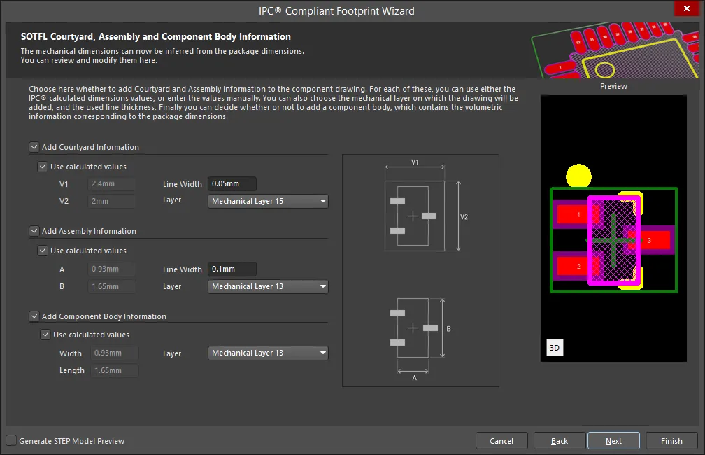
The SOTFL Courtyard, Assembly and Component Body Information page displays the inferred mechanical dimensions using the package dimensions previously defined.
Enable Add Courtyard Information and Add Assembly Information to add courtyard and assembly information to the component drawing. For each, you can use the IPC calculated dimensions or enter new values directly in the textboxes. If desired, enter a new Line Width directly in the textbox. You can also select the mechanical layer for courtyard and assembly by using the drop-down next to Layer and selecting the desired mechanical layer.
A component body contains the volumetric information corresponding to the package dimensions. Enable Add Component Body Information to include this information. Enable Use calculated values to use the values displayed or disable the option and enter new desired values. You can also select the mechanical layer for the component body by using the drop-down next to Layer and selecting the desired mechanical layer.
WIRE WOUND
Copy Link
Copied
WIRE WOUND
Precision Wire Wound Package Dimensions
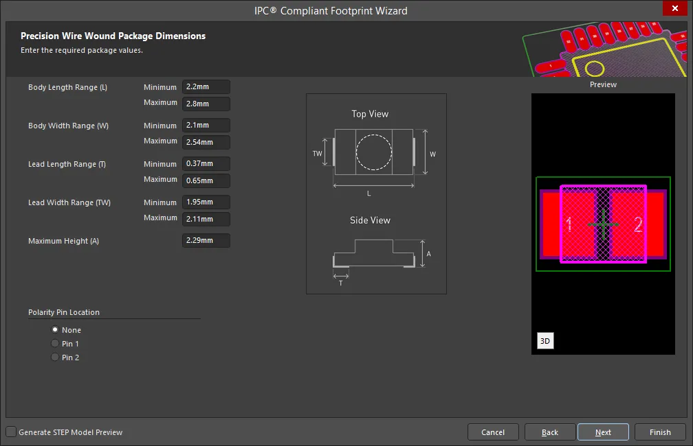
Use the Precision Wire Wound Package Dimensions page to set the required values for Body Length Range, Body Width Range, Lead Length Range, Lead Width Range, and Maximum Height.
Set the Polarity Pin Location by selecting either None, Pin 1, or Pin 2.
Precision Wire Wound Heel Spacing

Set the desired heel spacing values on the Precision Wire Wound Heel Spacing page.
Enable the Use calculated values checkbox to use the values currently displayed or enter new values directly in the textboxes for S Minimum and S Maximum.
Precision Wire Wound Solder Fillets

Set the required solder fillet values on the Precision Wire Wound Solder Fillets page. Solder fillet refers to the shape of the solder joint between the component lead and the PCB pad. Adequate fillet is required to ensure both the strength and reliability of the solder joints. A solder joint may be described by three fillets: toe, heel, and side.
Minimum values for solder fillets at the toe, heel and side of the component lead have been determined by IPC based on industry empirical knowledge and reliability testing. Enable Use default values to use the values displayed or you can adjust them to suit your specific needs.
Use the Board density Level drop-down to select the desired board density. Choose from Level A - Low density, Level B - Medium density, and Level C - High density. The Preview region is dynamically updated to show your changes.
To update the values for Toe Fillet (JT Min), Heel Fillet (JH Min), and Side Fillet (JS Min), the Use default values option must be disabled. Enter the new values directly in the textboxes.
Precision Wire Wound Component Tolerances

Enter the required values for component tolerances on the Precision Wire Wound Component Tolerances page.
Component manufacturers usually specify the minimum and maximum value for each package dimension. Component tolerance ranges are derived by subtracting the minimum value from the maximum value. You can adjust three of these ranges.
If the displayed values are correct for your current situation, enable the Use calculated component tolerances textbox. If the tolerance values need to be adjusted, ensure Use calculated component tolerances is disabled then enter the new values directly in the textboxes next to Tolerance on the overall width of the component, including leads, Tolerance on the inner distance between the heels of the opposing rows of leads, and Tolerance on the width of the component leads.
Precision Wire Wound IPC Tolerances
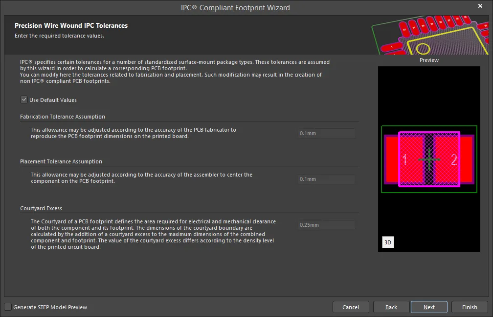
IPC specifies certain tolerances for a number of standardized surface-mount package types. These tolerances are assumed by the Wizard in order to calculate a corresponding PCB footprint. You can modify the tolerances related to fabrication and placement on the Precision Wire Wound IPC Tolerances page. Enable Use Default Values to accept the displayed values. You can change the values for Fabrication Tolerance Assumption, Placement Tolerance Assumption, and Courtyard Excess by entering the new values directly in the textboxes.
Modifying the IPC Tolerances may result in PCB footprints that are not IPC compliant.
Precision Wire Wound Footprint Dimensions
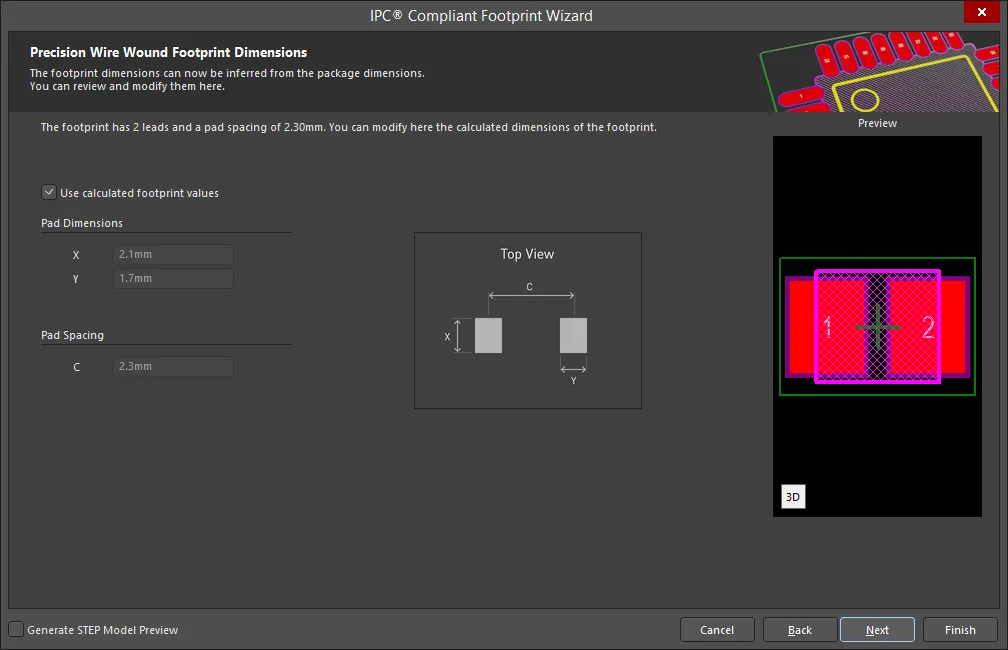
The Precision Wire Wound Footprint Dimensions page displays the inferred footprint dimensions using the package dimensions previously defined. To use the displayed values, enable Use calculated footprint values or enter new values for Pad Dimensions and Pad Spacing.
Precision Wire Wound Silkscreen Dimensions

The Precision Wire Wound Silkscreen Dimensions page displays the inferred silkscreen dimensions using the package dimensions previously defined. You can further define the silkscreen dimensions by entering a new value for the Silkscreen Line Width. Enable Use calculated silkscreen dimensions to use the values displayed or disable the option and enter the desired values.
Precision Wire Wound Courtyard, Assembly and Component Body Information

The Precision Wire Wound Courtyard, Assembly and Component Body Information page displays the inferred mechanical dimensions using the package dimensions previously defined.
Enable Add Courtyard Information and Add Assembly Information to add courtyard and assembly information to the component drawing. For each, you can use the IPC calculated dimensions or enter new values directly in the textboxes. If desired, enter a new Line Width directly in the textbox. You can also select the mechanical layer for courtyard and assembly by using the drop-down next to Layer and selecting the desired mechanical layer.
A component body contains the volumetric information corresponding to the package dimensions. Enable Add Component Body Information to include this information. Enable Use calculated values to use the values displayed or disable the option and enter new desired values. You can also select the mechanical layer for the component body by using the drop-down next to Layer and selecting the desired mechanical layer.
Choosing the Footprint Name and Description
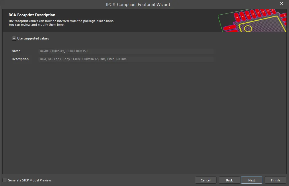
The Footprint Description page is used to name and describe your new footprint. Altium Designer uses the information you input in the Wizard to suggest a name and description. Enable Use suggested values to use the Name and Description the system has entered. Enter any desired changes directly in the textboxes.
Selecting the Footprint Destination

Use the Footprint Destination page to select the location for the newly-created footprint to be stored.
Select Existing PcbLib File if you want the footprint stored in an existing PCB Library file. You can enter the file directly in the textbox or use the  to open a dialog to search for the desired file.
Select New PcbLib File if you want to store the footprint in a new PCB Library file. Enter the name of the new PCB Library file in the textbox. The system will append the new library file name with the extension .PcbLib.
Select Current PcbLib File to store the footprint in the displayed PCB Library file.
Enable Produce 3D/STEP model to generate a 3D STEP model.
If you have a valid 'MCAD Co-Designer - SOLIDWORKS(R)' license, you can choose to save the model as file type Parasolid. Click the drop-down to the right of Format then select Parasolid. The file shown in the External File text box is now a *.x_t file. This is the name and location of the file that will be saved.
Select either Embedded (default) or External File. Select External File to save your 3D STEP model as an external file. The default file type is STEP and the file name appears in the External File text box with *.step as the file extension. If desired, click  to browse and select the folder in which to save your generated 3D STEP model.
Closing the Wizard

Click Finish to close the Wizard.
Creating a Footprint Using the Footprint Wizard
Copy Link
Copied
The PCB footprint editor includes a Footprint Wizard. This Wizard allows you to select from various package types and fill in appropriate information and it will then build the component footprint for you. Note that in the Footprint Wizard you enter the sizes required for the pads and component overlay.
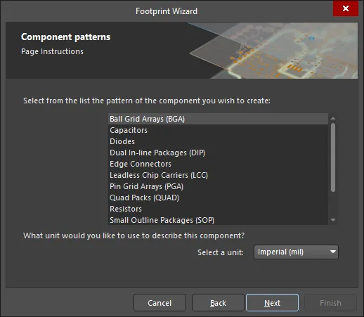
To launch the Footprint Wizard, select Tools » Footprint Wizard from the main menus or right-click in the design space and choose the Tools » Footprint Wizard command from the context menu. Follow the Footprint Wizard's intuitive pages to set up the particular component footprint as required.
Wizard Navigation
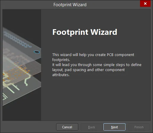
- Click Cancel to close the Footprint Wizard.
- Click Back to navigate to the previous screen.
- Click Next to navigate to the next screen.
- Click Finish to close the Footprint Wizard. This option is available only on the final page of the Wizard.
Selecting Component Patterns
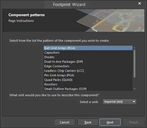
Use the Component patterns page to specify the pattern of the component you want to create.
Select the desired pattern from the list then use the drop-down to select the unit for the component (Imperial (mil) or Metric (mm)).
The subsequent pages of the Wizard change depending upon the component pattern selected. Find the desired component pattern in the following list then click on the link to access the information regarding that component pattern.
Ball Grid Arrays (BGA)
Copy Link
Copied
Ball Grid Arrays (BGA)
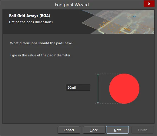
To change the pads' diameters, click on the value and enter the new value.
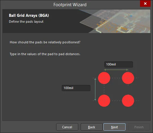
To change the pad to pad distances, click on the values and enter the new value.
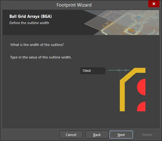
To change the outline width, click on the value and enter the new value.
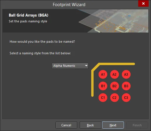
Use the drop-down to select either Alpha Numeric or Numeric naming style.
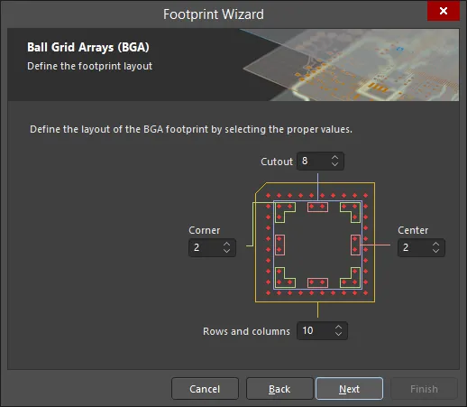
Use the up and down arrows in each region to define the footprint value for Cutout, Center, Rows and columns, and Corner.
Capacitors
Copy Link
Copied
Capacitors

Use the drop-down to select the type of capacitor you want to design. Choose from Through Hole or Surface Mount.
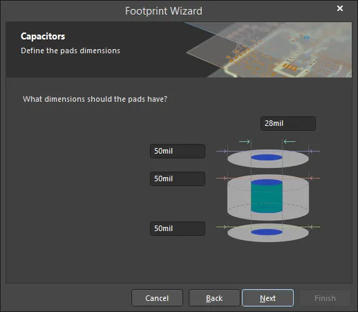
To change the pads' dimensions, click on the values and enter the new values.
This page will have a slightly different look if Surface Mount was selected, however, its functionality is the same.
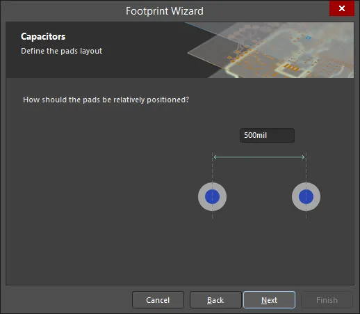
To change the pads positioning, click on the value and enter the new value.
This page will have a slightly different look if Surface Mount was selected, however, its functionality is the same.

This page appears if Through Hole was selected. If Surface Mount was selected, the page below appears.
Use the drop-down to select the capacitor's polarity, either Not Polarised or Polarised. Use the drop-down to select the capacitor's mounting style, either Axial or Radial.

This page appears if Surface Mount was selected.
Use the drop-down to select outline type, either Non polarised Outline or Polarised Outline.

To change the outline dimensions, click on the values and enter the new values.
This page will have a slightly different look if Surface Mount was selected, however, its functionality is the same.
Diodes
Copy Link
Copied
Diodes
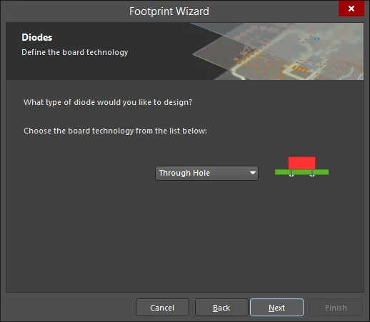
Use the drop-down to select the type of diode you want to design. Choose from Through Hole or Surface Mount.
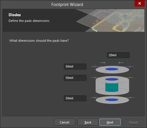
To change the pads' dimensions, click on the values and enter the new values.
This page will have a slightly different look if Surface Mount was selected, however, its functionality is the same.
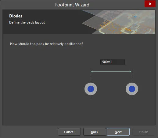
To change the pads positioning, click on the value and enter the new value.
This page will have a slightly different look if Surface Mount was selected, however, its functionality is the same.
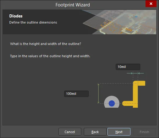
To change the outline dimensions, click on the value and enter the new value.
This page will have a slightly different look if Surface Mount was selected, however, its functionality is the same.
Dual In-line Packages (DIP)
Copy Link
Copied
Dual In-line Packages (DIP)
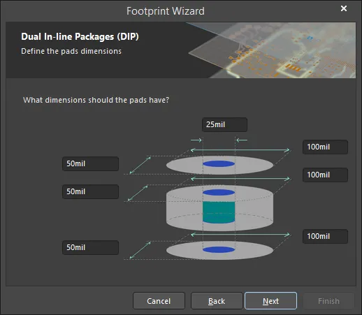
To change the pads' dimensions, click on the value and enter the new required value.

To change the pads' layout, click on the value and enter the new required value.

To change the outline width, click on the value and enter the new required value.

Use the up and down arrows to select the total number of pads.
Edge Connectors
Copy Link
Copied
Edge Connectors

To change the pads' dimensions, click on the value and enter the new required value.
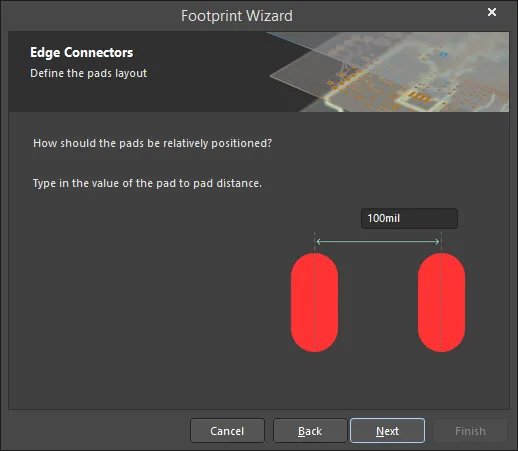
To change the pad to pad distance, click on the value and enter the new required value.

Use the up and down arrows to select the number of pads. Click the green arrow to change the naming order. The arrow will dynamically change to display the order.
Leadless Chip Carriers (LCC)
Copy Link
Copied
Leadless Chip Carriers (LCC)
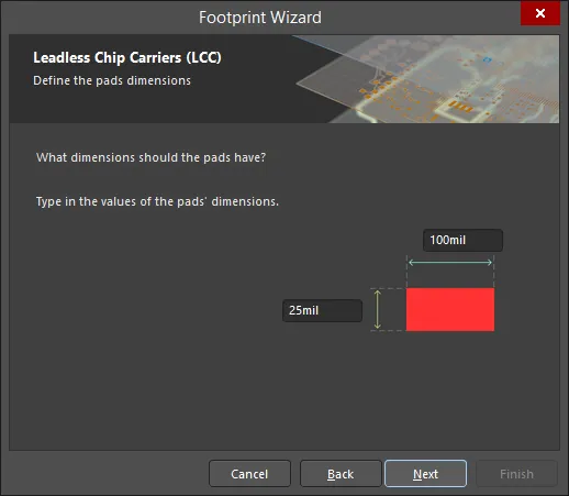
To change the pads' dimensions, click on the value and enter the new required value.

Use the drop-down to choose the pads' shapes. Select from Round or Rectangular for For the first pad, then select Round or Rectangular for For the other pads.
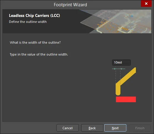
To change the outline width, click on the value and enter the new required value.
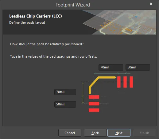
To change the pads' positioning, click on the value and enter the new required value.
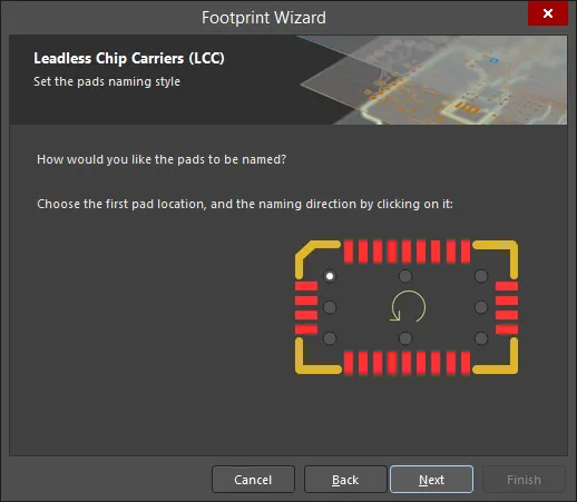
Click one of the radio buttons to select the first pad's location. Choose the naming direction by clicking on the green arrow. The arrow will dynamically update to display the order.
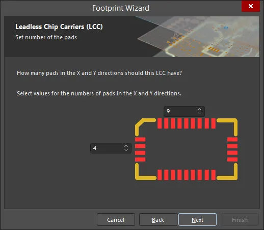
Use the up and down arrows to select the number of pads for both X and Y.
Pin Grid Arrays (PGA)
Copy Link
Copied
Pin Grid Arrays (PGA)
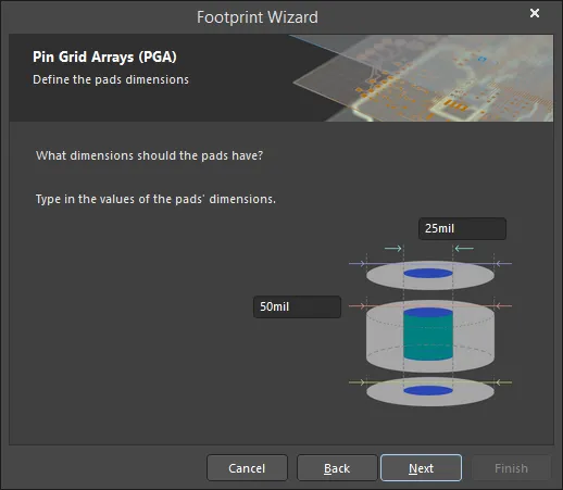
To change the pads' dimensions, click on the value and enter the new required value.
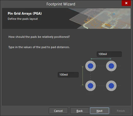
To change the pad to pad distances, click on the value and enter the new required value.
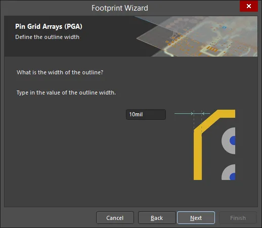
To change the outline width, click on the value and enter the new required value.
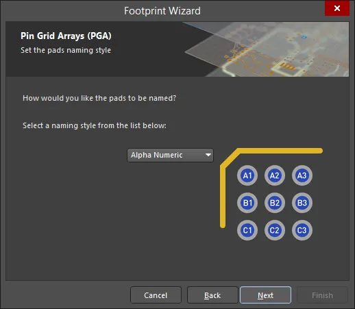
Use the drop-down to select the pads naming style, either Alpha Numeric or Numeric.
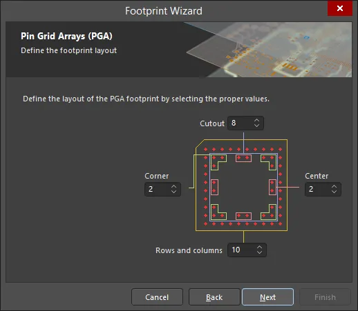
Use the up and down arrows in each region to define the footprint value for Cutout, Center, Rows and columns, and Corner.
Quad Packs (QUAD)
Copy Link
Copied
Quad Packs (QUAD)

To change the pads' dimensions, click on the value and enter the new required value.
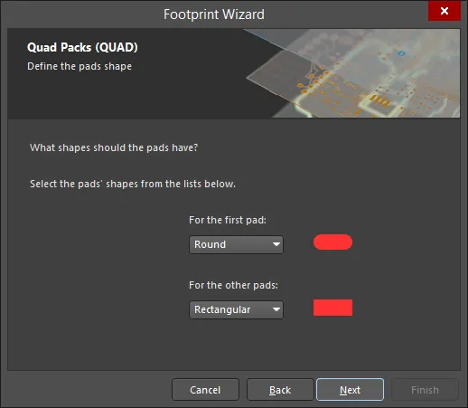
Use the drop-down to choose the pads' shapes. Select from Round or Rectangular for For the first pad, then select Round or Rectangular for For the other pads.
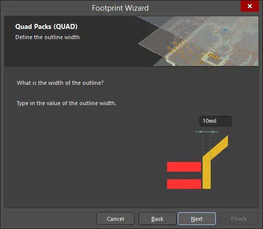
To change the outline width, click on the value and enter the new required value.
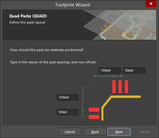
To change the pads' positioning, click on the value and enter the new required value.

Click one of the radio buttons to select the first pad's location. Choose the naming direction by clicking on the green arrow. The arrow will dynamically update to display the order.

Use the up and down arrows to select the number of pads for both X and Y.
Resistors
Copy Link
Copied
Resistors
Defining the Board Technology
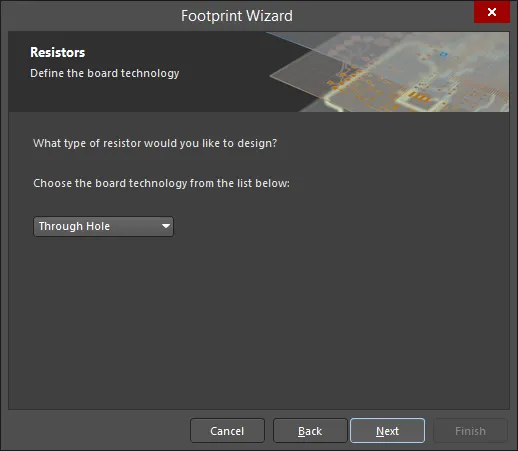
Select the type of resistor you want to design from the drop-down. Choices include Through Hole or Surface Mount.
Defining the Pads Dimensions
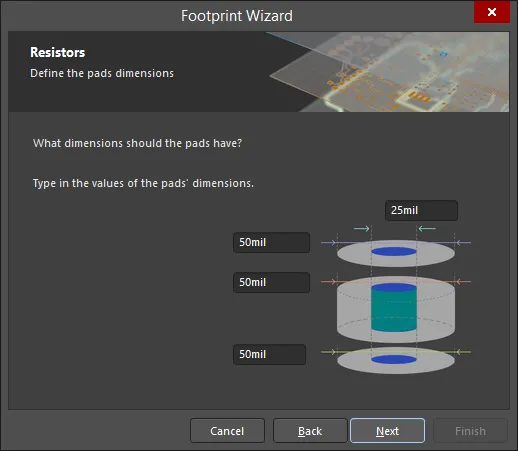
To change the pads' dimensions, click on the value and enter the new value.
This page will have a slightly different look if Surface Mount was selected, however, its functionality is the same.
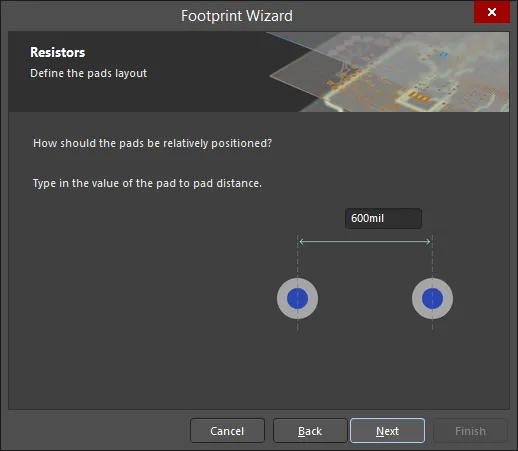
To change the pad to pad distance, click on the value and enter the new value.
This page will have a slightly different look if Surface Mount was selected, however, its functionality is the same.
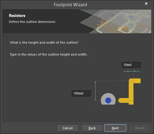
To change the outline dimensions, click on the value and enter the new value.
This page will have a slightly different look if Surface Mount was selected, however, its functionality is the same.
Small Outline Packages (SOP)
Copy Link
Copied
Small Outline Packages (SOP)
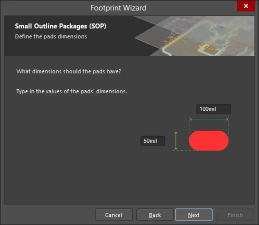
To change the pads' dimensions, click on the value and enter the new value.
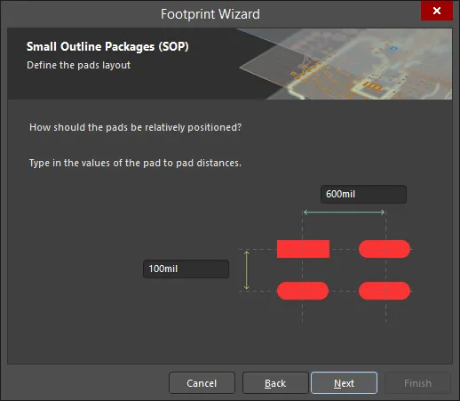
To change the pad to pad distance, click on the value and enter the new value.
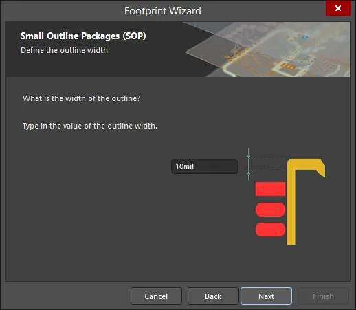
To change the outline width, click on the value and enter the new value.
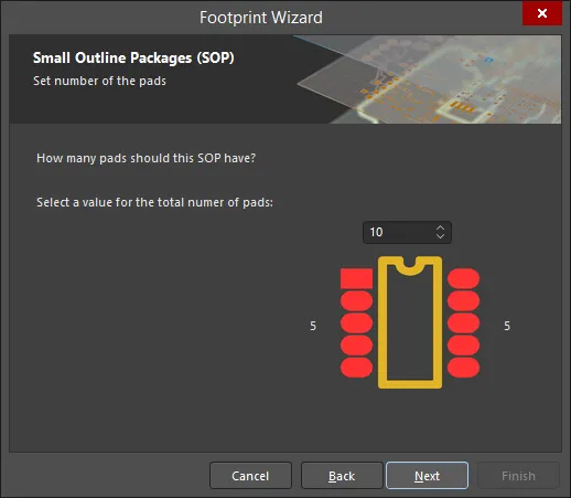
Use the up and down arrows to select the total number of pads.
Staggered Ball Grid Arrays (SBGA)
Copy Link
Copied
Staggered Ball Grid Arrays (SBGA)
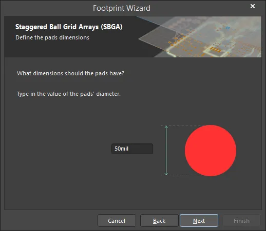
To change the pads' dimensions, click on the value and enter the new value.

To change the pad to pad distance, click on the value and enter the new value.
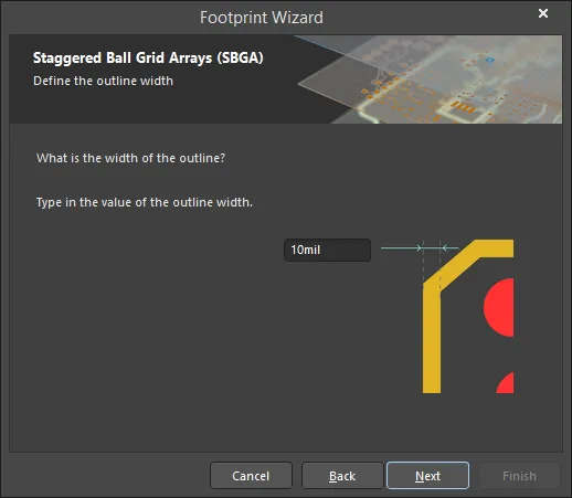
To change the outline width, click on the value and enter the new value.
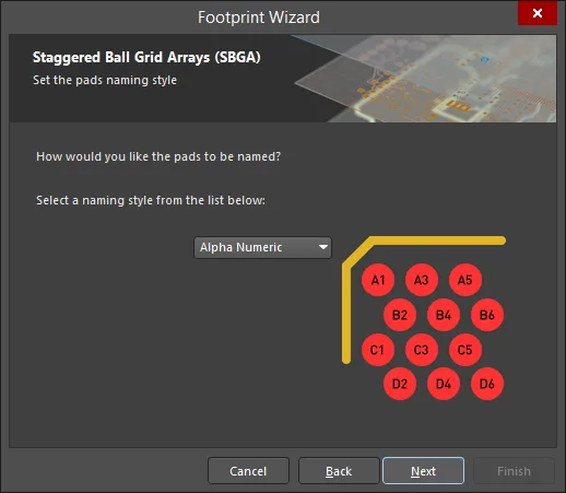
Use the drop-down to select the pads naming style, either Alpha Numeric or Numeric.
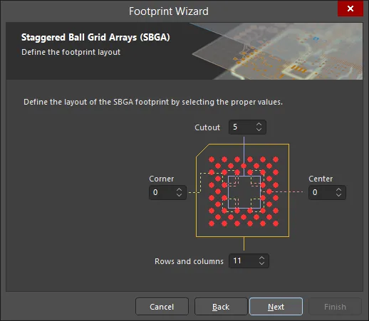
Use the up and down arrows in each region to define the footprint value for Cutout, Center, Rows and columns, and Corner.
Staggered Pin Grid Arrays (SPGA)
Copy Link
Copied
Staggered Pin Grid Arrays (SPGA)
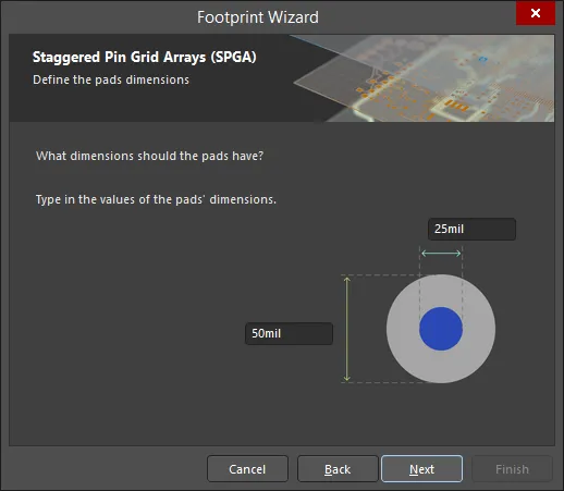
To change the pads' dimensions, click on the value and enter the new value.
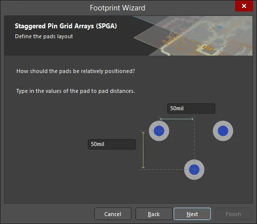
To change the pad to pad distance, click on the value and enter the new value.

To change the outline width, click on the value and enter the new value.
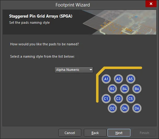
Use the drop-down to select the pads' naming style, either Alpha Numeric or Numeric.
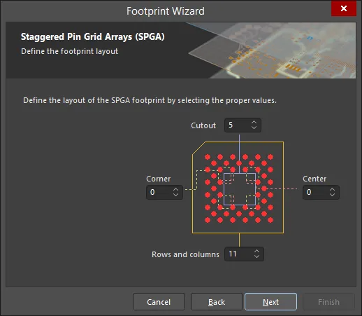
Use the up and down arrows in each region to define the footprint value for Cutout, Center, Rows and columns, and Corner.
Setting the Component Name
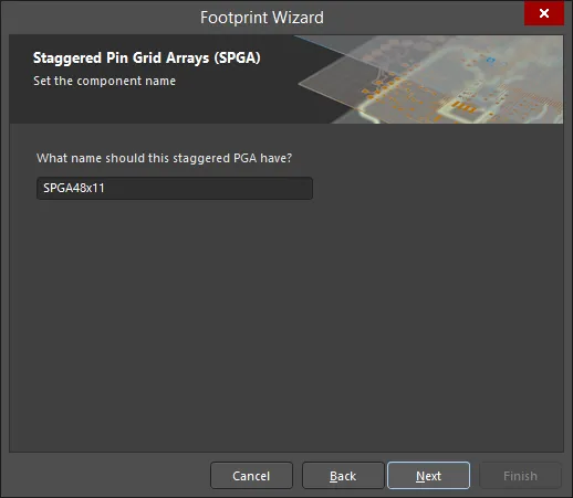
Enter a name for the component in the textbox.
Completing and Closing the Wizard
Click Finish to close the Wizard.
Solder and Paste Mask Expansions
Copy Link
Copied
To check that solder and/or paste masks have been correctly defined in the PCB footprint editor, open the View Configuration panel and enable the show option ( ) option for each mask layer.
The ring that appears around the edge of each pad in the color of the Top Solder Mask layer represents the edge of the solder mask shape protruding by the expansion amount from under the multi-layer pad because multi-layer is at the top of the layer drawing order; it is drawn on top. The Layer Drawing Order is set on the PCB Editor - Display page of the Preferences dialog).
The image below shows a PCB footprint with a purple (color of the Top Solder Mask layer) border that appears around the edge of each pad.

To quickly walk through layers, use the Single Layer Mode (Shift+S) in combination with Ctrl+Shift+Wheel roll.
By default, the shape that is created on the mask layers is the pad shape, expanded or contracted by the amount specified by the
Solder Mask Expansion and
Paste Mask Expansion design rules set in the PCB on which the footprint is placed. In some cases, you might need to override the expansion design rules and specify a mask expansion as a pad attribute, select from a standard set of predefined mask shapes, or create your own custom shape. In these situations, you can configure paste/solder masks for a selected pad in its
Properties panel -
learn more. Alternatively, you can place suitable primitives (Regions, Tracks, etc.) on the required mask layer.
Parameter Support
Copy Link
Copied
Parameters applied to objects in Altium Designer provide a powerful and flexible means of adding additional information to a PCB design. Applied as properties of the parent object, parameters can be applied at a range of levels, including projects, documents, templates, and individual objects within a design document.
Parameters that become available in the PCB space can be used to filter Queries, Design Rules, Scripts, and Variants, and can be applied in PCB component libraries for invoking custom strings in placed Footprints.
Parameters via an Engineering Change Order
The PCB parameter capabilities are based on functionality included in the ECO mechanism and PCB document, which allow user-defined component parameters to be transferred to and retained in the PCB space. This is a one-way transfer and the passed parameters are read-only in the PCB domain.
The parameter transfer is done by creating an ECO from the schematic to PCB with the Design » Update PCB Document menu command.
When the ECO is executed (by using the Execute Changes button), any new user-defined schematic component parameters will be transferred to the corresponding footprint reference in the PCB design.
The detection and migration of parameters to the PCB is determined by the project's options settings (Project » Project Options). In the Project Options dialog, set the difference detection and modification behavior in the Differences Associated with Parameters section of the Comparator tab and the Modifications Associated with Parameters section of the ECO Generation tab.
To view the transferred parameters in the PCB editor, double-click a component to open the Properties panel then choose the Parameters tab. The tab will list the current user parameters that have been assigned to the selected component footprint. Parameters for a selected component footprint also are available in the Components panel.
Information Reference Links
The PCB domain automatically accepts the predefined ComponentLink parameters from the schematic. These are defined as parameter pairs (Description and link URL) that normally establish data reference links to specific files or internet locations – typically a manufacturer web site or datasheet URL.
In both the schematic and PCB design space, the links are accessed from the right-click context menu when hovering over a component (under the References sub-menu options). The specialized parameters are added in the Properties panel, and when transferred to the PCB space, they appear as a component footprint parameter.
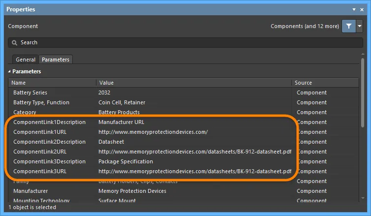
Parameters in Source Footprints
Parameters passed to the PCB can be used for providing additional board production or functional information via component footprints. By adding special parameter strings to footprints at the source library level, the custom strings will be interpreted on the target mechanical layer or overlay.
A special string representing a user-defined parameter can be added to the source component footprint using the special strings button and drop-down ( ) in the Properties panel.
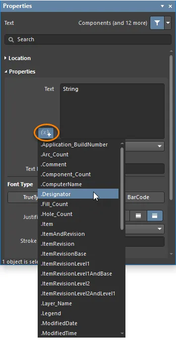
In the below library footprint, the special string .Designator has been placed on the Mechanical 2 layer.

A special string representing a user parameter can be added to the component footprint.
When that custom parameter has also been applied to schematic components and the parameter data has been transferred to the PCB, the interpreted footprint strings will appear on both the board view and generated output files. In this case the special parameter string contains a custom component part identifier to aid assembly.
The application of the user parameters to component footprints as special strings can serve a range of other custom PCB requirements, including function labels for switches and connectors, where a 'function' parameter string might be placed on the Top Overlay in footprints for those component types.
To see the interpreted value of special strings on the board layout, enable Special Strings option under the Additional Options region of the View Options tab in the View Configuration panel. Special strings are always converted in generated output files.
In the schematic editor, if desired, enable the Display Names of Special Strings that have No Value Defined option on the Schematic – Graphical Editing page of the Preferences dialog.
Parameter Queries
Parameter strings in the PCB domain are also accessible through the Altium Designer query language, and therefore, are available for object filtering functions, including the Find Similar Objects feature.
To perform a similar objects selection, right-click on a component then select Find Similar Objects from the context menu to open the Find Similar Objects dialog.
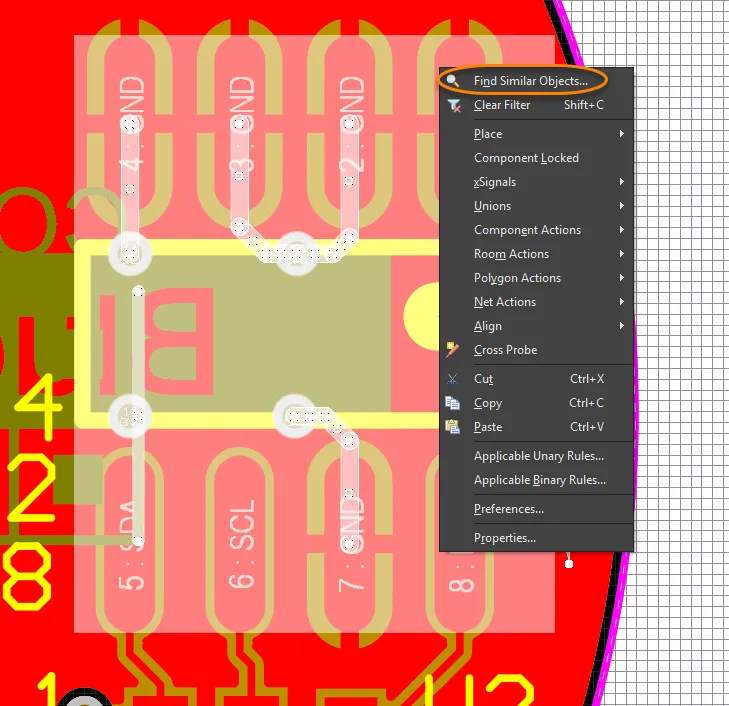
The Find Similar Objects dialog includes a Parameters section where the filtering options can be selected as required.

The PCB Filter panel can apply parameter-specific query words as filter criteria, and can be used for creating Design Rules based on PCB parameters.
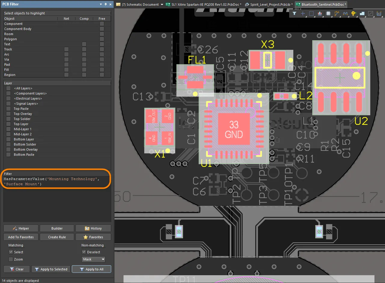
Several query words are available for working with PCB footprint parameters, including specific function words for converting string values to numbers (such as StrToNumber). The string Value conversions are unit-aware (V, mA, mV, kOhm etc.,) and allow the query result to be determined by the numerical processing of a parameter value string.
The supported Unit Types that can be nominated in the queries are:
- % – Percent
- A – Current
- C – Temperature
- dB – Decibels
- F – Capacitance
- G – Conductance
- H – Inductance
- Hz – Frequency
- Kg – Mass
- m – Length
- Ohm – Resistance
- Q – Charge
- s – Time
- V – Voltage
- W – Power
- Z – Impedance

Several Parameter query words are available for working with PCB component footprint parameters.
The example shown in the Query Helper dialog above processes the Voltage Rating parameter for each component (using the string-to-number conversion – StrToNumber(Unit Value, Unit Type)) to determine if its value is greater than 50V. When applied in the PCB Filter panel, the example board layout exposes a single high-voltage component, C1 (which has a Voltage Rating value of 3kV).
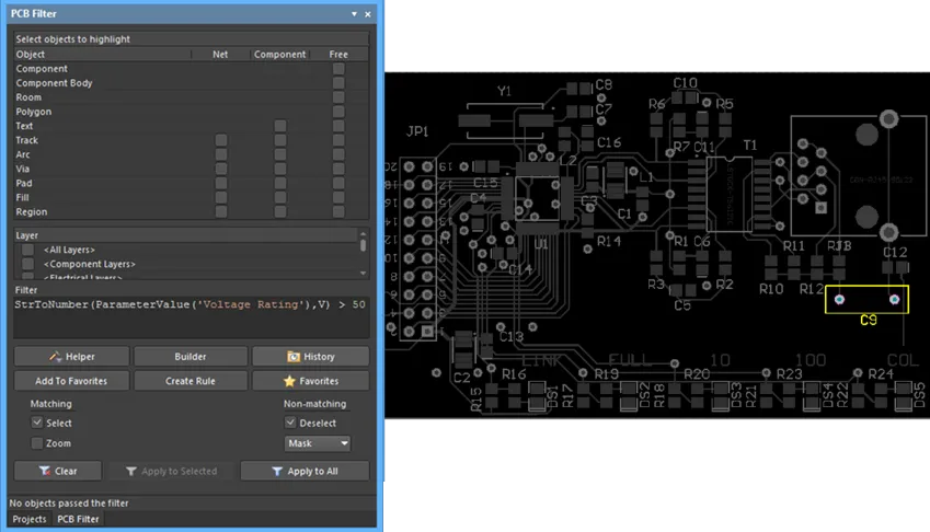
Scientific E notation is also supported, so, for example, a query to filter capacitor values over 1nF would be similar to:
StrToNumber(ParameterValue('CapacitanceValue'), F) > 1e-9
Alternatively, the number conversion function could be used for both the returned ParameterValue and the comparison value:
StrToNumber(ParameterValue('CapacitanceValue'), F) > StrToNumber('1nF', F)
Rules and Scripts
PCB parameter queries can also be applied to Altium Designer Scripts and Design Rules. The latter might perform layout validation checks, such as detecting footprint parameters in order to assess component placement or layer assignment. Note that the functions listed in the Query Helper dialog above are available to the Scripting language.
The below example shows the capacitor voltage rating query (see the filter query above) applied to a component placement rule, which, when run, checks for specific clearance values for components detected as high voltage (>50V) devices.
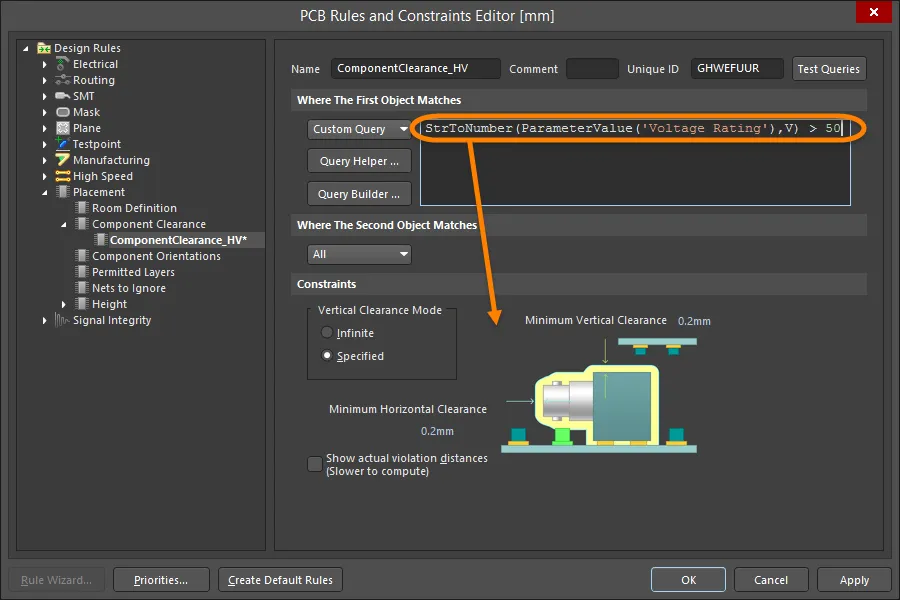
Design rules defined by specific footprint parameters, as transferred from the schematic space, can be used for detecting custom layout conditions.
Similarly, custom PCB parameters can be used to check component layer compatibility, for example, where a component does not support wave soldering and therefore placement of the Bottom Layer. Here, an object matching query that processes a custom ‘WaveSoldering’ parameter (Yes/No) might be applied to the Permitted Layers Rule.

The (batch) Rule will subsequently check the value of that component parameter and create a violation if a component is not compatible with placement on the Bottom Layer.
Variants
Parameters transferred to the PCB that are included in variations of the design (Design Variants) are processed with Variant selection.
In practice, a varied component parameter in the PCB space will be dynamically detected by a query string, or, for example, displayed on a board layer through a special string.
User-defined Footprint Parameters
User-defined parameters for footprints are supported in Altium Designer. The Parameters region on the Footprint tab of the Properties panel in its Library Options mode can be used to view and edit footprint parameters when no object is selected in the PCB footprint editor design space.
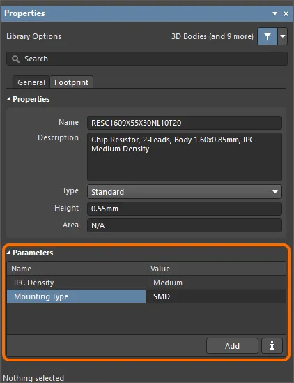
When the component is placed on the PCB, you can see these parameters in the Properties panel in the Component mode on the Parameters tab.
- Footprint parameters of components placed on a PCB will be propagated to footprints in libraries generated by the Make PCB Library or Make Integrated Library command of the PCB editor's main menu.
- Footprint parameters are supported by Altium Designer’s Comparison engine and for generated Pick and Place and ODB++ output.
Altium MCAD CoDesigner supports the placement of native MCAD components in the MCAD according to the configured linking. In some cases, several footprints with different models are linked to one component (e.g., a LED that can be mounted on a PCB in two ways: vertically, with straight legs, or horizontally, with bent legs). Using the footprint parameters, you can now refer to the different MCAD models from those different footprints. Learn more about
Linking Native ECAD and MCAD Design Components.
Designator and Comment Strings
Copy Link
Copied
Default Designator and Comment Strings
When a footprint is placed on a board, it is given a Designator and Comment based on information extracted from the schematic view of the design. Placeholders for the Designator and Comment strings do not need to be manually defined since they are added automatically when the footprint is placed on a board. The locations of these strings are determined by the Designator and Comment string Autoposition option in the Properties panel in Parameter mode when the designator or comment string is selected in the design space. The default position and size of Designator and Comment strings are configured in the respective Primitive on the PCB Editor - Defaults page of the Preferences dialog.

Additional Designator and Comment Strings
There may be situations when you want additional copies of the designator or comment strings. As an example, your assembly house wants a detailed assembly drawing with the designator shown within each component outline, while your company requires the designator to be located just above the component on the component overlay on the final PCB. This requirement for an additional designator can be achieved by including the .Designator special string in the footprint. A .Comment special string also is available for stipulating the location of the comment string on alternate layers or locations.
To cater to the assembly house's requirements, the .Designator string would be placed on a mechanical layer in the library editor and printouts that included this layer could then be generated as part of the design assembly instructions.
Handling Special Layer-specific Requirements
Copy Link
Copied
There are a number of special requirements a PCB component can have, such as needing a glue dot or a peel-able solder mask definition. Many of these special requirements will be tied to the side of the board on which the component is mounted and must flip to the other side of the board when the component is flipped.
Rather than including a large number of special-purpose layers that may rarely be used, Altium Designer's PCB editor supports this requirement through a feature called layer pairs. A layer pair is two mechanical layers that have been defined as a pair. Whenever a component is flipped from one side of the board to the other, any objects on a paired mechanical layer are flipped to the other mechanical layer in that pair. Using this approach, you select a suitable mechanical layer to include the glue dot (or other special requirements) and define its shape using the available objects. When you place that footprint onto a board, you must set up the layer pairing. This instructs the software on which layer it must transfer objects to when this component is flipped to the other side of the board. You cannot define layer pairs in the PCB footprint editor; this is done in the PCB editor.
Layer Pairing needs to be defined before the component gets flipped. If the pairing is defined after the component has moved to the bottom side, the mechanical contents will flip but stay on their original layer. If you forget to create layer pairs before flipping, you can update from the library to refresh the instance of the component placed on the board.
The Names of Mechanical Layers can be edited directly from the View Configurations panel by right-clicking then selecting Edit Layer.
A common approach to managing mechanical layer usage is to assign a dedicated layer number for each required mechanical layer function. This approach requires all designers to adhere to the same layer assignment and numbering scheme. It can also create difficulties when components are obtained from other sources that do not follow the same assignment and numbering scheme. If a different scheme has been used, the design objects must be moved from their current mechanical layer to the mechanical layer assigned for that function.
This issue is resolved with the introduction of the Layer Type property. When a component is placed from a library into the PCB editor, or copied from one library to another, or created by the IPC Footprint Wizard, existing Layer Type assignments are automatically matched, regardless of the mechanical layer number(s) assigned to those Layer Types. The objects are relocated on the correct layer(s) according to their Layer Type. If the software is unable to match by Layer Type, it will fall back to matching by Layer Number.
For both individual mechanical layers and Component Layer Pairs, you can select a Layer Type from a pre-defined list of types. You may access the dialogs shown below by right-clicking on an individual layer, then selecting the Edit Layer or Add Component Layer command from the menu.
Adding Height to a PCB Footprint
Copy Link
Copied
At the simplest level of 3D representation, height information can be added to a PCB footprint. To do this, open the Properties panel in its Library Options mode (active when no object is selected in the design space) and enter the recommended height for the component in the Height field on the Footprint tab of the panel.
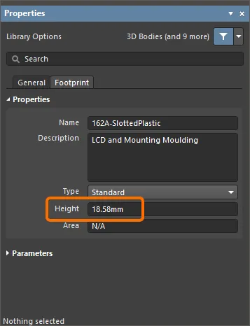
Height design rules can be defined during board design (click Design » Rules in the PCB Editor), typically testing for maximum component height in a class of components or within a room definition.
A better option for defining height information would be to attach 3D Bodies to the PCB footprint.
Managing Components With Routing Primitives
Copy Link
Copied
When a design is transferred, the footprint specified in each component is extracted from the available libraries and placed on the board. Then each pad in the footprint has its net property set to the name of the net connected to that component pin in the schematic. All objects touching a pad connect to the same net as the pad.
The PCB editor includes a comprehensive net management tool. To launch it select Design » Netlist » Configure Physical Nets from the main menus to open the Configure Physical Nets dialog. Click the Menu button for a menu of options. Click the New Net Name header drop-down to select the net to assign to the unassigned primitives.
Footprints With Multiple Pads Connected to the Same Pin
The footprint shown below, a SOT223 transistor, has multiple pads that are connected to the same logical schematic component pin - Pin 2. To make this connection, two pads have been added with the same designator - '2'. When the Design » Update PCB command is used in the Schematic Editor to transfer design information to the PCB, the resulting synchronization will show the connection lines going to both pads in the PCB editor, i.e. they are on the same net. Both of these can be routed.

SOT223 footprint showing two pads with a designator of 2.
Silkscreen Preparation
Copy Link
Copied
To assist in resolving common Design for Manufacture (DFM) issues faced by having silkscreen overlapping exposed copper and holes, the PCB footprint editor includes a dedicated feature for preparing the silkscreen for your footprints. These issues can be effectively addressed by:
- automated clipping of silkscreen lines and arcs;
- automated clipping or movement of fills and regions;
- automated movement of silkscreen text strings.
The silkscreen preparation tool can also be accessed when designing a PCB:
learn more.
To access the silkscreen preparation tool in the PCB footprint editor, use the Tools » Silkscreen Preparation command from the main menus. The Silkscreen Preparation dialog will open.

Use the dialog to configure the settings of the silkscreen object clipping/movement. The available options are:
- Clip to Exposed Copper – enable to automatically clip objects to exposed copper.
- Clip to Solder Mask Openings – enable to automatically clip objects to solder mask openings.
- Silkscreen Clearance – define the minimum acceptable value between silkscreen objects and exposed copper / solder mask openings and holes.
- Min Remaining Length – if the line/arc length is less than the defined value after clipping, the objects will be removed from the footprint. Note that this length is the vertex-to-vertex length, not the edge-to-edge length (show image
![]() ).
).
- Move Text – enable to move silkscreen text strings away from exposed copper / solder mask openings and holes if the distance between them is less than the Silkscreen Clearance. The movement is limited by the Max Distance value.
- Fill & Region – select an action to be performed for fills and regions when the distance between them and exposed copper / solder mask openings and holes is less than the Silkscreen Clearance:
None – fills and regions remain untouched.Clip – fills and regions will be clipped to maintain the Silkscreen Clearance. Fills are converted to regions if applicable.Move – fills and regions will be moved away from exposed copper / solder mask openings and holes. The movement is limited by the Max Distance value.
- Max Distance – define a maximum distance to which text strings, component designators, fills and regions can be moved to maintain the Silkscreen Clearance.
Click OK to perform clipping and/or movement of silkscreen objects according to the settings in the dialog.
If an action cannot be performed for an object (e.g., a text string cannot be moved due to the limitation of Max Distance), a message for this object will appear in the Messages panel.
Below is shown an example of the silkscreen preparation tool performance.
Generating a Component Report
Copy Link
Copied
To generate a report for the active PCB footprint, choose the Reports » Component command from the main menus. After launching the command, the report will be generated (<PCBLibraryDocumentName>.CMP) in the same folder as the source PCB library document and will automatically be opened as the active document in the main design window. The report lists information including footprint dimensions and a breakdown of the primitive objects that constitute the footprint and the layers on which they reside.
The report will be added to the Projects panel as a free document under the Documentation\Text Documents sub-folder.
Working with Jumper Components
Copy Link
Copied
Jumpers, also referred to as wire links, allow you to replace routing with a Jumper component, which is often an essential ingredient to successfully designing a single-sided board.
Early printed circuit boards were all single sided. To successfully implement all of the connections, jumpers or wire links were often used to create another layer of connectivity, which could pass across the printed routing. The image below shows an example of Jumpers being used to implement the routing on one side of the board.
Note the representation of a Jumper, with a curved connection line between the two pads. In the image, the jumper connection lines are shown in different colors because they inherit the color assigned to the net.

What Defines a Jumper?
To act as a jumper, you need:
How Jumpers are Used
After placing a Jumper in the design space you will need to set the Net attribute of one of the pads manually in the Properties panel since there is no automatic net inheritance. Note that if the component is defined as a Jumper, then the other pad will automatically inherit the same Net name.
Controlling the Display of Jumpers
The View menu includes a Jumpers sub-menu that allows control over the display of Jumper components.

There are also Jumper sub-menus in the Netlist popup menu (N shortcut).

Use the available commands to:
The query keyword IsJumperComponent is available for filtering and rule definition.
Jumpers and the Bill of Materials
Jumpers are typically pieces of tinned copper wire that are bent to the correct length, meaning they need to be in the BOM. To support this, Jumpers also can be included on the schematic so that they are included in the Bill of Materials. The Synchronizer and the Report engine have the following behavior for synchronizing Jumpers:
- The component itself is synchronized.
- Net properties of Jumper pins are not synchronized.
- The Jumper is included in the BOM.
Suggested Workflow for Working with Jumpers
The following description is one approach to working with Jumper components. This workflow starts at the schematic, but you can also start by placing the Jumper footprints directly onto the PCB. The main reason for starting on the schematic is that when the design is transferred to the PCB workspace, the footprints will have the correct component Type of Jumper. If you place them directly from the PCB library into the PCB workspace, the component Type will default to Standard, so you will need to manually set it.
Create the Jumper Footprints
Create a footprint for each length jumper that will be used. Typically jumpers are designed in pre-defined lengths, for example, in increments of 0.1 inch (100 mils).
As mentioned above, there are two conditions that make a Jumper a Jumper:
- Both pads in the Jumper must have their Jumper value set to the same, non-zero value in the Properties panel. Note that it does not matter if the pads in all Jumper footprints used on a board design have the same Jumper value.
- The Jumper Component must have its Type set to
Jumper in the Properties panel. Note that this can only be set once the footprint has been placed into the PCB workspace; it cannot be set in the PCB Library editor.
The image below shows a typical Jumper in the PCB Library editor. Both pads have the Jumper value of 1.

Create the Schematic Jumper Component
On the schematic side, you can either:
- Create a single Jumper component, then add to it all of the different length Jumper footprints that you need.
- Create an individual Jumper component for each different length Jumper footprint that will be used.
Once the symbol has been created:
- Set the default Designator.
- Set the Component Type to
Jumper.
- Add the various Jumper footprints to the Models list.
- Define the other component properties you need, such as the Description and any required component Parameters on the Parameters tab.
Placing Jumpers onto the Schematic
Once the Jumper has been designed, you can place a number of them onto the schematic. At this stage, you probably do not know how many you will need, however, extras can easily be deleted. Keep in mind they are on the schematic to ensure they go into the BOM; they do not need to be wired into the circuit at each location that they end up being used. For that reason, it makes sense to place them all on the same schematic sheet, perhaps with other BOM-only hardware, such as screws.
When a Design » Update PCB Document command is performed, all of the jumpers will be placed into the PCB workspace using the default footprint to the right of the board shape.
Position and Routing the Jumpers on the PCB
The image below shows the PCB, almost completely routed. Note the remaining connection lines showing where the routes are not complete. There are also a number of un-placed Jumper components to the right of the board.
The routing for each of these connections cannot be completed because there is no route path available on this single-sided design. To complete them, the Jumper components will be used.
To complete a connection with a Jumper:
- Drag a jumper component into position on the board. If it is not long enough, either press Tab while moving the Jumper or double-click once it is placed to open the Component mode of the Properties panel.
- In the Footprint region of the Properties panel, enter the Footprint Name, or click the
 to open the Browse Libraries dialog to select a footprint.
-
To make it easier to include the Jumper in the BOM, enter a suitable identifying string in the Comment field. In the image below, the footprint name has been copied and pasted into the Comment field since it describes how long the jumper is.
- Position the Jumper in the required location.
-
Double-click to edit one of the pads then select the required net name from the Net drop-down list in the Properties region of the Properties panel. The other pad in the Jumper will automatically be assigned the same net name.
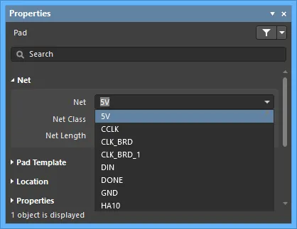
- Once all Jumpers have been placed, delete any unused Jumpers from the board.
- Run the Design » Update Schematics command to push the footprint and comment changes back to the schematic.
- The last step is to remove any unused Jumper components from the schematic. These can be identified by switching to one of the schematic sheets and running the Design » Update PCB Document command. The Engineering Change Order dialog will open and list any extra components on the schematic; note their designators then close the ECO dialog and delete those excess Jumpers from the schematic.
