Parts are available for placement in the schematic editor in the following ways:
- Choose Home | Circuit Elements | Part from the main menus.

- Right-click in the design space then choose Place » Part from the context menu.
Placement from the Libraries Panel
In the schematic editor, the part selection and placement process can be done from the Libraries panel.
Only components that have linked models can be placed in a design. Such components are distinguished with the

icon in the component list in the
Libraries panel.
- Use the drop-down at the top of the panel to choose the component type or your favorite component list.
- Use the search field below the top drop-down to filter the list and speed the searching process or scroll and select the required part.
- Click Place, double-click, or click and drag to place the selected component onto the active schematic sheet. While the part is floating on the cursor, it can be rotated (press Spacebar), mirrored along an axis (press X or Y), or edited (press Tab) before placement.
- The columns shown in the list of components in the currently selected library can be reorganized (click and drag).
Graphical Editing
Graphical editing for a part is limited to moving, rotating, and mirroring. When a part is selected in the design space, a dashed selection box will appear around it. To graphically manipulate a selected component:
- Press Delete to remove the selected part.
- Click and hold to move the selected part. The cursor will jump to the nearest electrical hotspot (the wiring end of the nearest pin).
- Press the Spacebar to rotate the part counterclockwise or Shift+Spacebar for clockwise rotation. The action can also be performed while dragging the object. Rotation is in increments of 90°.
- While a part is moving on the cursor, press the X or Y key to mirror it along that axis.
Working Between the Schematic Component and the PCB Component
The software includes tools to help work between the component on the schematic and that same component on the PCB. These tools include cross probing and cross selection.
Cross Probing
As the name implies, Cross Probe allows you to click on a component in one editor and jump to that component in the other editor. To cross probe:
- Click Cross Probe located on the schematic or PCB editor menu on the Tools tab.
- When you click the component in the schematic editor, it will be centered and zoomed in the PCB editor and vice versa.
- The default behavior is to remain in the same editor, ready to cross probe another component. To switch to the other editor as you cross probe, hold the Ctrl key.
Cross Select Mode
Cross Select Mode selects the same component in the other editor. Note that it does not zoom and center. Cross Select Mode is either on or off. Choose Home | Clipboard | Select » Cross Select Mode to toggle the mode on/off. Select multiple components by holding the Shift key as you click to select.
To clear the selection of (or de-select) the object, use the Esc key.
Non-Graphical Editing
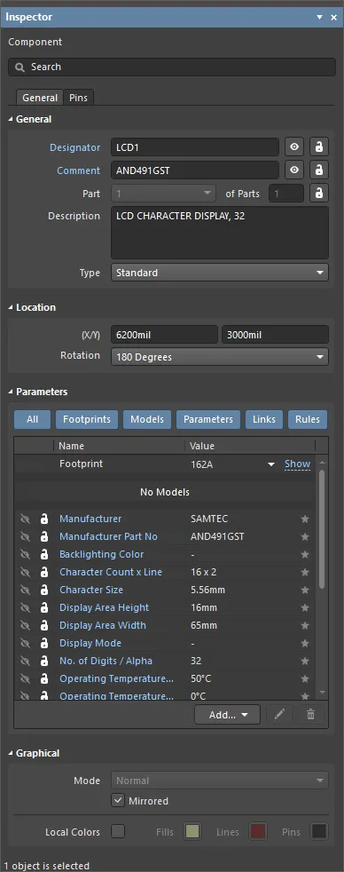
This method of editing uses the associated Inspector panel mode to modify the properties of a part object.

During placement, the Component mode of the Inspector panel can be accessed by pressing the Tab key. Once the component is placed, all options appear.
After placement, the Component mode of the Inspector panel can be accessed in one of the following ways:
- If the Inspector panel is already open, select the object, right-click then choose Properties from the context menu.
- With the object selected, choose View | Schematic | Inspector from the main ribbons.
Editing Multiple Objects
The Inspector panel supports multiple object editing, where the property settings that are identical in all currently selected objects may be modified. When multiples of the same object type are selected manually, an Inspector panel field entry that is not shown as an asterisk (*) may be edited for all selected objects.