
TRANSLATE: KB: ポートクロスリファレンス表示を変更する
回路図にポート参照を追加したいのですが、スペースを節約するためにゾーンやグリッドの参照は含めたくありません。
Solution Details
The port cross reference details added to ports in your schematic by the command.
Reports » Port Cross Reference » Add to Project
The format is set in the Port Cross References section in the preferences here:
Preferences » Schematic » General » Port Cross References
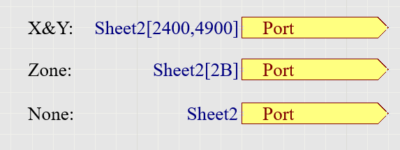
To remove the Zone or X and Y Coordinates, set the Location Style pull-down choice list to "None". Additional settings are available for the Sheet Style, including Name, Number, or None.
Once you select OK in the preferences, run the following command to see the changes:
Reports » Port Cross Reference » Update on Project
Further reading is available in our documentation:
Port Cross References
Update: With AD21.6 the Port Cross Reference Add and Remove commands were removed from the Reports menu and are replaced with the new Automatic Cross References Settings command. Selecting this command will open the Options tab of the Project Options dialog where you can toggle the feature on/off. This change is more thoroughly explained in this document:
Improved Schematic Cross References