デザイン・ディレクティブは、設計キャプチャ中に回路図上へ配置するオブジェクトで、ソフトウェアの他の部分へ渡す指示を指定するための手段を提供します。さまざまなデザイン・ディレクティブが用意されており、次の 2 つの方法で使用できます。
-
ソース回路図ドキュメントの自動コンパイルに関連付けられるディレクティブ。
-
回路図シート上で定義された情報を PCB へ渡すために使用されるディレクティブ。
以下のセクションでは、これらの領域と関連するディレクティブについて詳しく説明します。
コンパイル関連ディレクティブ
設計は時間とともに進化し、段階的にキャプチャされます。各段階が固まるたびに、その部分だけを他の設計部分から切り離してチェックしたくなることは珍しくありません。キャプチャ作業の途中段階で個々の回路図ドキュメント(またはプロジェクト全体)をコンパイルすると、まだキャプチャされていない回路や、未完成の回路断片間のインターフェース配線が原因で、多数のエラーメッセージが生成されることがよくあります。このようなメッセージは実際には価値がなく、本当に必要な情報の周囲にノイズを生むだけです。これらのコンパイルエラーを抑制する最も手早く簡単な方法は、No ERC または Compile Mask ディレクティブを配置することです。
No ERC ディレクティブ
No ERC ディレクティブは、回路内のノードに配置して、回路図プロジェクトの検証時に検出されるすべての Electrical Rule Check の警告および/またはエラー違反状態を抑制します。詳細については、Validating Your Design Project ページを参照してください。
Compile Mask ディレクティブ
No ERC ディレクティブは、設計内の少数の違反ピン、ポート、シートエントリ、ネットを抑制するには非常に有効です。しかし場合によっては、コンポーネントを含む設計のセクション全体を除外したいことがあります。そのような場合は、Compile Mask ディレクティブ(Place » Directives » Compile Mask コマンド)を使用するか、Active Bar 上部にあるディレクティブのドロップダウン内の Compile Mask ボタン( )をクリックして、そのマスクが含む設計領域をコンパイラから事実上隠します。これにより、まだ完成しておらず、コンパイルエラーを発生させることが分かっている回路に対して、エラーチェックを手動で抑制できます。アクティブなドキュメントやプロジェクトをコンパイルして、設計の他の特定領域の整合性を確認したいが、未完成部分に起因するコンパイラ生成メッセージという「ノイズ」は不要な場合に、非常に有用です。
その名称が示すとおり、このディレクティブは、定義されたマスクの境界 completely 内に収まるオブジェクトをコンパイラに無視させます。マスクは、ノートや矩形オブジェクトと同じ要領で配置します。
次の画像の例では、LCD1 デバイスへの配線がまだ完了していない回路図を示しています。この回路図だけをコンパイルすると(Project » Validate PCB Project)、未完成の回路が原因で多数の違反メッセージ(下に表示)が発生します。画像の上にカーソルを置くと、未完成の回路を囲むように Compile Mask ディレクティブを配置した場合の効果が表示されます。これらの違反はコンパイラによって無視され、一方で回路図上の残りの回路(完全に配線済み)はチェックされます。マスクの外接矩形の内部に完全に収まっている、真にマスクされたオブジェクトは、グレー表示になる点に注意してください。
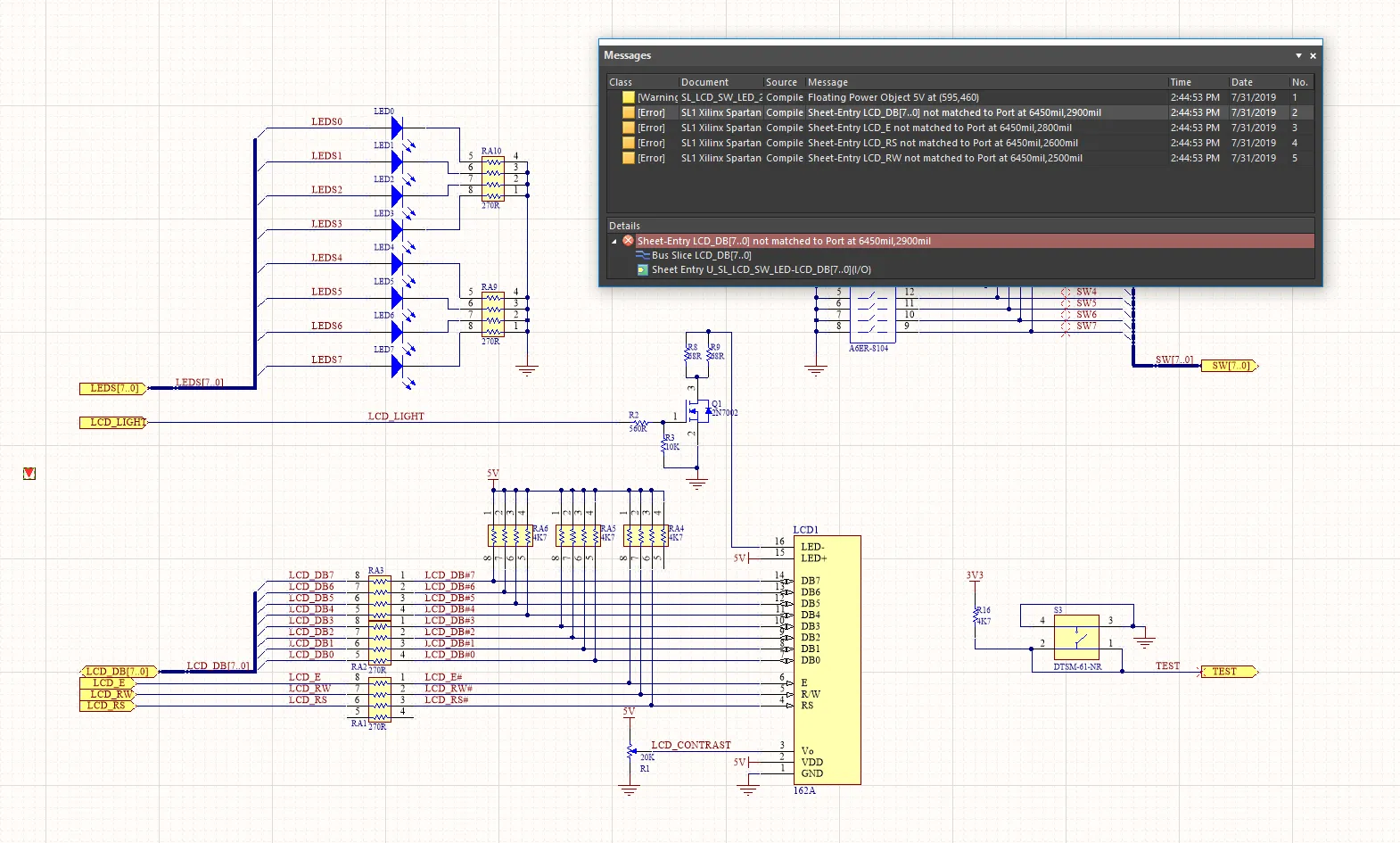
画像にカーソルを重ねると、未完成の回路によるコンパイラ違反を隠すために Compile Mask ディレクティブを使用した効果が表示されます。
コンパイルマスクは、展開(フルフレーム)モードと折りたたみ(小さな三角形)モードのいずれかで表示できます。これらのモードは、それぞれマスクが有効/無効である状態に対応します。配置済みコンパイルマスクの左上隅をクリックすると、表示モードを切り替えられます。この機能は、設計フローの一部としてシミュレーションを含める場合に便利です。
learn more。
コンパイルマスクは X 軸または Y 軸に沿って回転またはミラー反転できますが、マスク内の設計回路の向きには影響しません。
Compile Mask
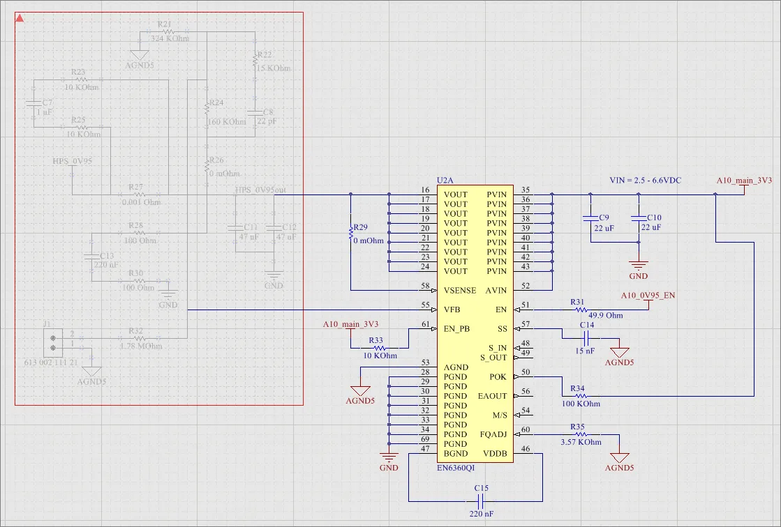 上記の回路図の左側に表示されているのが、配置された Compile Mask です。
概要
Compile Mask は、Project » Validate Project コマンドを使用して検証を実行する際に、その内部に含まれる設計領域をコンパイラから事実上隠すためのデザイン・ディレクティブです。まだ完成しておらず、検証エラーを生成することが分かっている回路に対するエラーチェックを手動で抑制する手段を提供します。現在のプロジェクトについて、設計の他の特定領域の整合性を確認するために検証を行いたいが、未完成部分に関連するコンパイラ生成メッセージの煩雑さは避けたい、といった状況で有用です。
「Compile Mask」という名称ではありますが、このディレクティブはコンパイルという行為自体には関連していません。コンパイルは、Altium Designer の Dynamic Compilation 機能により、各ユーザー操作の後に自動的に実行されます。Compile Mask が関与するのは、ユーザーがプロジェクトの検証を手動で実行する場合であり、これはコンパイルとは別個かつ明確に区別されるプロセスであり、ユーザーが手動で開始する必要があります。検証では、
Error Reporting タブおよび
Connection Matrix タブで定義された設定と組み合わせて、プロジェクト内の回路図ドキュメントに対して電気的およびドラフティング上のエラーをチェックします(
Project Options ダイアログ)。
利用可能性
Compile Mask は、回路図エディタでのみ配置可能です。Compile Mask を配置するには、次のいずれかを実行します。
-
メインメニューから Place » Directives » Compile Mask コマンドをクリックします。
-
デザインスペース上部にある Active Bar のディレクティブ・ドロップダウン内の Compile Mask ボタン(
 )をクリックします。関連コマンドにアクセスするには、Active Bar ボタンをクリックしたまま押し続けます。一度使用したコマンドは、そのセクションの Active Bar の最上部に表示されるようになります。
-
回路図エディタ内で右クリックし、Place » Directives » Compile Mask をクリックします。
配置
コマンドを起動すると、カーソルはコンパイルマスク配置モードを示す十字カーソルに変わります。配置は、次の手順で行います。
-
カーソルを位置決めし、マスクの最初の角を固定するためにクリックするか Enter を押します。
-
カーソルを移動してマスクのサイズを調整し、コンパイラから隠したい設計領域を完全に包み込むようにします。その後、対角の反対側の角を固定してマスクの配置を完了するために、クリックするか Enter を押します。マスクの境界内に完全に収まる設計オブジェクトはグレー表示になります。
-
続けて他のコンパイルマスクを配置するか、右クリックまたは Esc を押して配置モードを終了します。
グラフィカル編集
この編集方法では、デザインスペース内で配置済みコンパイルマスクオブジェクトを直接選択し、そのサイズ、形状、位置をグラフィカルに変更できます。
コンパイルマスクは、アクティブ(フルフレーム)モードと折りたたみ(枠付き三角形)モードのいずれかで表示でき、これらはそれぞれマスクが有効/無効である状態に対応します。配置済みコンパイルマスクの左上隅にある ▲ または ▼ アイコンをクリックして表示モードを切り替えます。
 左上の三角形をクリックして、コンパイルマスクを折りたたみ(無効化)ます。
アクティブ(展開)状態のコンパイルマスクオブジェクトを選択すると、次の編集ハンドルが使用可能になります。
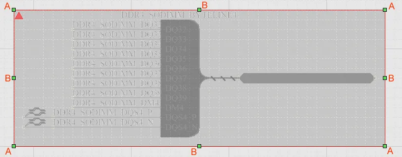 アクティブ状態で選択された Compile Mask。
-
A をクリック&ドラッグして、コンパイルマスクを縦横同時にリサイズします。
-
B をクリック&ドラッグして、コンパイルマスクを縦方向と横方向で個別にリサイズします。
-
編集ハンドル以外のコンパイルマスク上の任意の場所をクリックし、ドラッグして位置を変更します。ドラッグ中は、コンパイルマスクを回転(Spacebar/Shift+Spacebar)したり、ミラー反転(X 軸方向にミラーするには X キー、Y 軸方向にミラーするには Y キー)したりできます。
Compile Mask が折りたたみ状態の場合、ドラッグして新しい位置に移動することによる位置変更のみがグラフィカルに行えます。
Locked プロパティが有効になっているオブジェクトをグラフィカルに変更しようとすると、編集を続行するかどうかを確認するダイアログが表示されます。Preferences ダイアログの Schematic – Graphical Editing ページで Protect Locked Objects オプションが有効になっており、かつその設計オブジェクトに対して Locked オプションも有効になっている場合、そのオブジェクトは選択もグラフィカル編集もできません。ロックされたオブジェクトをクリックして選択し、List パネルで Locked プロパティを無効にするか、Protect Locked Objects オプションを無効にして、そのオブジェクトをグラフィカルに編集できるようにします。
非グラフィカル編集
非グラフィカル編集には、次の方法が利用できます。
Compile Mask ダイアログまたは Properties パネルによる編集
Panel page: Compile Mask Properties
この編集方法では、関連する Compile Mask ダイアログおよび Properties パネルモードを使用して、Compile Mask オブジェクトのプロパティを変更します。
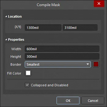
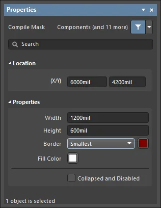
配置後、Compile Mask ダイアログには次の方法でアクセスできます。
-
配置済みコンパイルマスクオブジェクトをダブルクリックする。
-
コンパイルマスクオブジェクトを選択し、右クリックしてコンテキストメニューから Properties を選択する。
配置中に、Properties パネルの Compile Mask モードには Tab キーを押すことでアクセスできます。コンパイルマスクが配置されると、すべてのオプションが表示されます。
配置後、Properties パネルの Compile Mask モードには、次のいずれかの方法でアクセスできます。
-
Properties パネルがすでにアクティブな場合は、コンパイルマスクオブジェクトを選択する。
-
コンパイルマスクオブジェクトを選択した後、デザインスペース右下の Panels ボタンから Properties パネルを選択するか、メインメニューから View » Panels » Properties を選択する。
Double Click Runs Interactive Properties オプションが
Preferences ダイアログの
Schematic - Graphical Editing page で無効(デフォルト)になっている場合、プリミティブをダブルクリックするか、選択したプリミティブを右クリックして
Properties を選択すると、ダイアログが開きます。
Double Click Runs Interactive Properties オプションが有効な場合は、
Properties パネルが開きます。
ダイアログとパネルで利用できるオプションは同じですが、オプションの順序や配置は若干異なる場合があります。
複数オブジェクトの編集
Properties パネルは複数オブジェクトの編集をサポートしており、現在選択されているすべてのオブジェクトで同一のプロパティ設定をまとめて変更できます。同じ種類のオブジェクトが複数選択されている場合(手動選択、Find Similar Objects dialog 経由、または Filter や List パネル経由)、Properties パネルでアスタリスク(*)が表示されていないフィールドは、選択されているすべてのオブジェクトに対して編集できます。
List パネルによる編集
Panel pages: List Panels、SCH Filter
List パネルは、1 つ以上のドキュメントからの設計オブジェクトタイプを表形式で表示し、オブジェクト属性の迅速な確認と変更を可能にします。適切なフィルタリングと組み合わせて使用いることで(パネルの Include オプションを使用してオブジェクトタイプを選択するか、該当する Filter パネルまたは Find Similar Objects dialog を使用する)、アクティブなフィルタの範囲に含まれるオブジェクトのみを表示できます。表示されたオブジェクトのプロパティは、List パネル内で直接編集できます。
Compile Mask Properties
Schematic Editor のオブジェクトプロパティは、配置されたオブジェクトの表示スタイル、内容、および動作を指定するための設定可能なオプションです。各オブジェクトタイプのプロパティ設定は次のように定義されます。
-
Post-placement settings – すべての Compile Mask オブジェクトプロパティは、デザインスペースで配置済みの Compile Mask が選択されているときに、Compile Mask ダイアログおよび Properties パネルで編集できます。


ダイアログとパネルで利用できるオプションは同じですが、オプションの順序や配置は若干異なる場合があります。
Location
-
(X/Y)
-
X (最初のフィールド) - オブジェクトの基準点の現在の X(水平)座標で、現在のデザインスペース原点に対する相対位置です。編集してオブジェクトの X 位置を変更します。値はメートル法またはヤード・ポンド法のいずれでも入力でき、現在のデフォルト単位以外の値を入力する場合は単位を含めて入力します。
-
Y (2 番目のフィールド) - オブジェクトの基準点の現在の Y(垂直)座標で、現在の原点に対する相対位置です。編集してオブジェクトの Y 位置を変更します。値はメートル法またはヤード・ポンド法のいずれでも入力でき、現在のデフォルト単位以外の値を入力する場合は単位を含めて入力します。
Properties
-
Width - オブジェクトの幅を入力します。
-
Height - オブジェクトの高さを入力します。
-
Border - ドロップダウンを使用して、希望するボーダーを選択します。
-
Fill Color - カラーボックスをクリックして、オブジェクトに使用する色を選択します。
-
Collapsed and Disabled - チェックボックスをオンにして、オブジェクトを折りたたんで無効化します。
PCB 関連ディレクティブ
Altium Designer は統合設計環境として、PCB のレイアウトを行う前に PCB 要件を定義できる機能を提供します。これは、回路図シート上に配置されたオブジェクトにパラメータを追加・指定することで実現されます。
コンポーネント、シートシンボル、ポートなどの特定の回路図設計オブジェクトの場合、該当するパラメータをそのオブジェクトのプロパティの一部として追加します。ワイヤやバスなどのネットオブジェクトの場合、パラメータをワイヤやバス自体のプロパティとして直接追加することはできません。その代わり、情報を保持するために必要なパラメータは、専用の設計ディレクティブを使用して指定します。
ディレクティブを使用して指定でき、設計の同期時に適切な PCB ベースの定義へ転送される情報は次のとおりです。
-
PCB レイアウト制約
-
ディファレンシャルペア
-
ネットクラス
回路図内に設計ディレクティブを含めることで、設計エンジニアは明示的な設計制約を指定でき、回路図が設計のマスターレコードとして維持されます。設計の修正は回路図側でのみ行い、その内容を PCB 側へ反映させます。これは、複数の人間が設計に関わる場合、特に地理的に離れている場合に重要になります。メールや電話のやり取りで相互に伝達しようとする代わりに、設計をキャプチャしている担当者が、レイアウト段階で特定の制約が確実に使用されるようにできます。
この機能の中心となるのが Parameter Set directive です。
これらは本質的にはユーザー定義の Parameter Set オブジェクトであり、回路図設計内のネットオブジェクトに関連付けることができます。PCB Layout ディレクティブをワイヤ、バス、またはシグナルハーネス上に配置して、関連付けられたネットに対して 1 つ以上の設計制約を定義します。回路図から PCB を作成すると、PCB Layout ディレクティブ内の情報を使用して、該当する PCB デザインルールが作成されます。PCB Layout ディレクティブで指定された情報は、そのディレクティブが接続されているネット(またはネットの集合)にのみ適用されます。

Parameter Set ディレクティブ。
これは、Parameter Set ディレクティブが接続されているネットを対象とする任意数のパラメータのコンテナとして機能します。パラメータを持たないデフォルトの Parameter Set ディレクティブを配置(Place » Directives » Parameter Set)し、必要なパラメータを後から追加することもできます。以下のセクションでは、これらのパラメータベースのディレクティブの使用方法を詳しく見ていきます。ユーザー定義(Parameter Set)および事前定義(Differential Pair)の両方の parameter set ディレクティブが利用可能です。空の parameter set と事前定義の parameter set の唯一の違いは、事前定義の parameter set には、後述するようにパラメータが含まれている点です。
Moving from Directives to the Constraint Manager
設計要件を定義する従来のアプローチでは、回路図エディタと PCB エディタで別々に扱っていました。すなわち、回路図エディタでは Directives、PCB エディタでは Design Rules を使用します。この分離は、設計要件を定義するための別個のエディタである Constraint Manager の導入によって解消されました。これにより、設計プロセスの任意の段階で要件を設定・編集できるようになりました。1 つのプロジェクトでは、どちらか一方のアプローチしか使用できません。簡単な確認方法としては、Design メニュー内に Constraint Manager エントリがあるかどうかを確認します。存在しない場合(代わりに PCB エディタの Design メニューに Rules エントリがある場合)、そのプロジェクトは従来の Design Rules アプローチを使用していることになります。
Constraint Manager が使用されている場合、parameter set および differential pair ディレクティブを使用して定義されたネットクラス、ディファレンシャルペア、ディファレンシャルペアクラス、およびルールは、回路図から PCB を更新する際に not 検出および転送されません。転送されるのは、Constraint Manager 内で定義されたネットクラス、ディファレンシャルペア、ディファレンシャルペアクラス、およびルールのみです。
回路図に配置されたディレクティブから、ルール、ネットクラス、ディファレンシャルペア、およびディファレンシャルペアクラスをインポートすることもできます。これは、回路図からアクセスした Constraint Manager の Physical または Electrical ビューの右クリックメニューから Import from Directives コマンドを使用して行います – learn more。ディレクティブから Constraint Manager へデータをインポートしてその変更を保存すると、インポートされたディレクティブは回路図デザインスペース上で青色(やや異なるシンボル)で区別されるようになる点に注意してください。これは、ディレクティブから Constraint Manager への一方向の移行が行われたことを示しており、青色のディレクティブは読み取り専用オブジェクト(それ以上の編集は不可)になります。
Parameter Set

Parameter Set
概要
parameter set は、回路図設計内のネットタイプオブジェクトに設計仕様を関連付けるための設計ディレクティブです。たとえば、2 本のネットをディファレンシャルペアのメンバーとして宣言するために parameter set を使用します。どの設計ディレクティブを配置しているかをソフトウェアが判断するのは、parameter set 内に特定の名前のパラメータが存在するかどうかに基づきます。
利用可能性
parameter set は回路図エディタでのみ配置可能です。デフォルト(空)の parameter set ディレクティブと、事前定義された(Differential Pair) parameter set ディレクティブの両方が利用できます。空の parameter set と事前定義の parameter set の唯一の違いは、事前定義の parameter set には、以下で説明するようにパラメータが含まれている点です。
対応するコマンドには、メイン Place メニューから次のようにアクセスします。
| • |
Place » Directives » Parameter Set |
 |
| • |
Place » Directives » Differential Pair |
 |
配置
parameter set は、次のオブジェクトにパラメータを付加するために使用できます。
コマンドを起動すると、カーソルは十字カーソルに変わり、設計ディレクティブ配置モードに入ります。 配置は次の操作で行います。
-
カーソルをワイヤまたは他のネットオブジェクト上に移動し、クリックするか Enter を押して配置します。
-
続けてディレクティブを配置するか、右クリックするか Esc を押して配置モードを終了します。
配置中に実行できる追加操作 – parameter set がまだカーソル上でフローティングしている間に実行できます。
-
Tab キーを押して配置を一時停止し、Properties パネルの Parameter Set mode にアクセスして、その場でプロパティを変更します。デザインスペースの一時停止ボタンオーバーレイ( )をクリックして配置を再開します。
-
移動の初期方向に応じて、水平方向または垂直方向の軸に移動方向を制限するには、Alt キーを押します。
-
弧を反時計回りに回転するには Spacebar を、時計回りに回転するには Shift+Spacebar を押します。この操作はオブジェクトをドラッグしている間にも実行できます。回転は 90° 刻みで行われます。
-
配置モード中に X または Y キーを押すと、パラメータセットを X 軸または Y 軸方向に反転できます。
配置中に属性を変更することもできます(
Tab を押して
Properties パネルを表示)。ただし、
Permanent オプションが
Schematic – Defaults ページ の
Preferences ダイアログで有効になっていない限り、これらの変更は以降の配置に対するデフォルト設定になります。このオプションが有効な場合、行った変更は配置中のオブジェクトと、同じ配置セッション中に配置される後続のオブジェクトにのみ影響します。
グラフィカル編集
この編集方法では、デザイン空間内で配置済みのパラメータセット指示子を直接選択し、その位置や向きをグラフィカルに変更できます。
デザイン空間でパラメータセット指示子を選択すると、その周囲に破線のボックスが表示されます。このボックスは指示子が占める領域のみを囲みます。セット内で可視性が有効になっている各メンバーパラメータについては、そのテキストフィールドと指示子本体を結ぶ破線が表示され、関連付けが確認できます。

破線ボックス内を任意の位置でクリックし、ドラッグして必要な位置にパラメータセットを再配置します。ドラッグ中は、パラメータセットを回転(Spacebar/Shift+Spacebar)したり、反転(X 軸または Y 軸方向に反転するには X または Y キー)したりできます。
パラメータセットのテキストフィールド(親指示子とは独立してグラフィカル編集可能)は、Schematic – Defaults ページ の Preferences ダイアログにある Style オプションを変更することでのみサイズ調整できます。そのため、これらのオブジェクトを選択しても編集ハンドルは表示されません。

破線ボックス内を任意の位置でクリックし、ドラッグして必要な位置にテキストオブジェクトを再配置します。ドラッグ中は、テキストオブジェクトを回転(Spacebar/Shift+Spacebar)したり、反転(X 軸または Y 軸方向に反転するには X または Y キー)したりできます。
Preferences ダイアログの Schematic – General ページ で Enable In-Place Editing オプションが有効になっている場合、(ルールとして追加されたパラメータを除き)デザイン空間内でパラメータの値を直接編集できます。テキストオブジェクトを選択してから一度クリックして機能を呼び出し、必要な新しい値を入力して、テキストオブジェクト以外の場所をクリックするか Enter を押して変更を確定します。
Locked プロパティが有効になっているオブジェクトをグラフィカルに変更しようとすると、編集を続行するかどうかを確認するダイアログが表示されます。Preferences ダイアログの Schematic – Graphical Editing ページで Protect Locked Objects オプションが有効であり、かつそのデザインオブジェクトに対して Locked オプションも有効な場合、そのオブジェクトは選択もグラフィカル編集もできません。ロックされたオブジェクトをクリックして選択し、List パネルで Locked プロパティを無効にするか、Protect Locked Objects オプションを無効にしてオブジェクトをグラフィカルに編集できるようにします。
非グラフィカル編集
次の非グラフィカル編集方法が利用できます。
Parameter Set ダイアログまたは Properties パネルによる編集
Panel page:Parameter Set Properties
この編集方法では、関連付けられた Parameter Set ダイアログおよび Properties パネルモードを使用して、パラメータセットオブジェクトのプロパティを変更します。
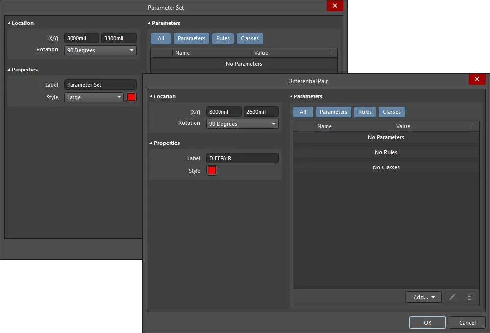
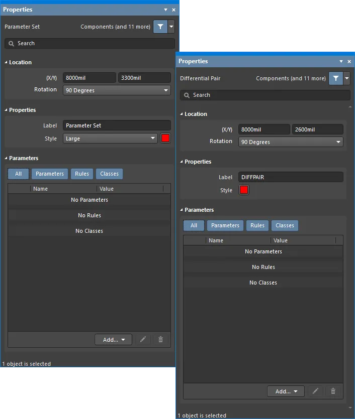
最初の画像の Parameter Set ダイアログ と、2 番目の画像の Properties パネルの Parameter Set モード
配置後、Parameter Set ダイアログには次の方法でアクセスできます。
-
配置済みのパラメータセットオブジェクトをダブルクリックする。
-
パラメータセットオブジェクト上にカーソルを置き、右クリックしてコンテキストメニューから Properties を選択する。
配置中は、Tab キーを押すことで Properties パネルの Parameter Set モードにアクセスできます。パラメータセットが配置されると、すべてのオプションが表示されます。
配置後、Properties パネルの Parameter Set モードには、次のいずれかの方法でアクセスできます。
-
Properties パネルがすでにアクティブな場合は、パラメータセットオブジェクトを選択する。
-
パラメータセットオブジェクトを選択した後、デザイン空間右下の Panels ボタンから Properties パネルを選択するか、メインメニューから View » Panels » Properties を選択する。
Preferences ダイアログの
Schematic – Graphical Editing ページ で
Double Click Runs Interactive Properties オプションが無効(デフォルト)な場合、プリミティブをダブルクリックするか、選択したプリミティブを右クリックして
Properties を選択すると、ダイアログが開きます。
Double Click Runs Interactive Properties オプションが有効な場合は、
Properties パネルが開きます。
Parameter Set のプロパティには、配置モードに入る前に
Preferences ダイアログの
Schematic – Defaults ページ からアクセスできます。これにより、オブジェクトのデフォルトプロパティを変更でき、以降に配置するオブジェクトに適用されます。
複数オブジェクトの編集
Properties パネルは複数オブジェクトの編集をサポートしており、現在選択されているすべてのオブジェクトで同一のプロパティ設定をまとめて変更できます。同一タイプの複数オブジェクトが、手動選択、Find Similar Objects ダイアログ、または Filter/List パネル経由で選択されている場合、Properties パネル内でアスタリスク(*)が表示されていないフィールドは、選択されているすべてのオブジェクトに対して編集できます。
List パネルによる編集
Panel pages: List Panels、SCH Filter
List パネルを使用すると、1 つ以上のドキュメントからデザインオブジェクトを表形式で表示でき、オブジェクト属性の迅速な確認と変更が可能になります。適切なフィルタリング(該当する Filter パネル または Find Similar Objects ダイアログ を使用)と組み合わせることで、アクティブフィルタの範囲に含まれるオブジェクトのみを表示でき、対象となる複数のデザインオブジェクトをより正確かつ効率的に編集できます。
注意
Parameter Set Properties
回路図エディタのオブジェクトプロパティは、配置されたオブジェクトの表示スタイル、内容、および動作を指定する設定可能なオプションです。
各オブジェクトタイプのプロパティ設定は、次の 2 通りの方法で定義されます。
-
Pre-placement settings – ほとんどの Parameter Set オブジェクトのプロパティ、または論理的に事前定義できるプロパティは、Preferences ダイアログの Schematic – Defaults page 上で編集可能なデフォルト設定として利用できます(ダイアログはデザインスペース右上の  ボタンからアクセスします)。右側にオプションを表示するには、Primitive List 内でオブジェクトを選択します。
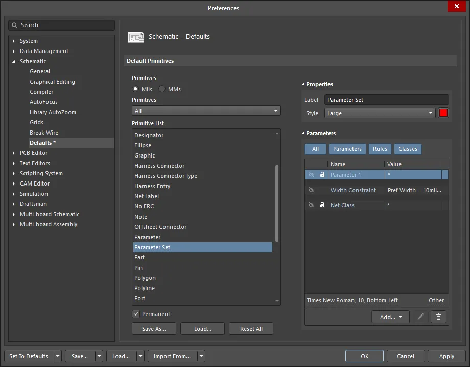
-
Post-placement settings – すべての Parameter Set オブジェクトのプロパティは、デザインスペースで Parameter Set が選択されているときに、 Parameter Setダイアログおよび Propertiesパネル内で編集できます。


Double Click Runs Interactive Properties オプションが
Preferences ダイアログの
Schematic – Graphical Editing page で無効(デフォルト)になっている場合、プリミティブをダブルクリックするか、選択したプリミティブを右クリックして
Properties を選択すると、ダイアログが開きます。
Double Click Runs Interactive Properties オプションが有効な場合は、
Properties パネルが開きます。
ダイアログとパネルでオプション自体は同じですが、オプションの順序や配置は若干異なる場合があります。
以下のプロパティ一覧では、Preferences ダイアログのデフォルト設定としては利用できないオプションには「Properties panel only」と記載されています。
Location
-
(X/Y)
-
X (最初のフィールド)– オブジェクトの基準点の現在の X(水平)座標で、現在のデザインスペース原点に対する相対値です。編集してオブジェクトの X 位置を変更します。値はメートル法またはヤード・ポンド法のいずれでも入力できます。現在のデフォルト単位以外の値を入力する場合は、単位を含めて入力してください。
-
Y (2 番目のフィールド)– オブジェクトの基準点の現在の Y(垂直)座標で、現在の原点に対する相対値です。編集してオブジェクトの Y 位置を変更します。値はメートル法またはヤード・ポンド法のいずれでも入力できます。現在のデフォルト単位以外の値を入力する場合は、単位を含めて入力してください。
-
Rotation – ドロップダウンを使用して回転角を選択します。
Properties
-
Label – Parameter Set のラベルです。必要に応じて編集します。
-
Style – ドロップダウンを使用してスタイルを選択します。カラーボックスをクリックすると、デフォルト色を選択できるドロップダウンにアクセスできます。
Parameters
-
Grid – 現在選択されているパラメータに関連付けられているパラメータの Name および Value を一覧表示します。追加後、Name および Value フィールドは編集可能です。Value はフィールドをクリックして目的のテキストを入力することで名前を付けることができます。Name フィールドは、Parameter Set オブジェクトの Properties パネルモードで Ctrl+Click を使用する場合にのみ変更できます。この方法では、Properties パネルの Parameter モードが開き、Name フィールド内に目的の名前を入力できます。ロックアイコン(
 )を使用して、一覧表示されたパラメータをロック/ロック解除します。目のアイコンを使用してパラメータを表示/非表示にします。All および個々のパラメータボタンを切り替えることで、この領域内にすべて、個別、または何も表示しないようにできます。ボタンがグレーのときはパラメータは無効、青のときは有効です。
-
Add – ドロップダウンを使用してクラスの種類を追加します:
-
Net Class – 新しいネットクラスを追加する場合に選択します。
-
Component Class – 新しいコンポーネントクラスを追加する場合に選択します。このオプションは、Parameter Set ダイアログまたは Properties パネルの Parameter Set イテレーションでのみ使用できます。
ブランケット内のコンポーネントに対してパラメータを設定するために、新しいクラス Component Class Name を追加できます。Component Class Name をコンポーネント(またはコンポーネントのグループ)に関連付けると、現在 Net Classes に対して行われているのと同様に、コンポーネントクラス、その名前およびメンバーに関する情報が PCB に送信されます。
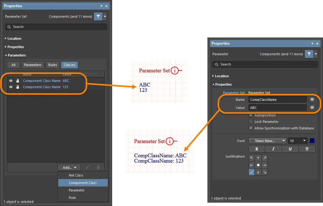
-
Diff. Pair Net Class – 新しいディファレンシャルペアネットクラスを追加する場合に選択します。このオプションは、Parameter Set ダイアログまたは Properties パネルの Differential Pair イテレーションでのみ使用できます。
-
Parameter – 新しいパラメータを追加する場合に選択します。
-
Rule – クリックして
![]() Choose Design Rule Type dialog を開き、新しいルールを選択できます。新しいルールを選択して OK をクリックすると、必要に応じて新しいルールを編集できるように Edit PCB Rule (From Schematic) ダイアログが開きます。
Choose Design Rule Type dialog を開き、新しいルールを選択できます。新しいルールを選択して OK をクリックすると、必要に応じて新しいルールを編集できるように Edit PCB Rule (From Schematic) ダイアログが開きます。
ディレクティブから Constraint Manager へデータをインポートしてデータを同期し、
Constraint Manager で変更を保存した後は、対応するディレクティブに対して、新しいネットクラス、ディファレンシャルペアクラス、コンポーネントクラス、またはルールを追加/編集/削除するためのコントロールは、
Properties パネル内でグレーアウトされます。
Constraint Manager にインポートされたエントリは、ディレクティブプロパティ内では実質的に読み取り専用となり、
Constraint Manager ボタンを使用して、
Properties パネルの
Parameters 領域上部でそれらをフィルタリングできるようになります。
鉛筆アイコン( )をクリックして Edit PCB Rule (From Schematic) ダイアログを開き、選択した項目を編集します。
 をクリックして選択した項目を削除します。
-
Font Settings – 表示されているフォントをクリックしてフォントスタイルを変更します。このオプションは、ネットクラス、ディファレンシャルペアネットクラス、パラメータ、またはルールが追加されている場合にのみ利用できます。
-
Other – ネットクラス、ディファレンシャルペアネットクラス、パラメータ、またはルールが追加されている場合、クリックしてドロップダウンを開き、追加オプションを変更します:
-
Show Parameter Name – 有効にするとパラメータ名を表示します。
-
Allow Synchronization with Database – 有効にするとデータベースと同期します。
-
X/Y – X および Y 座標を入力します。
-
Rotation – ドロップダウンを使用して回転角を選択します。
-
Autoposition – チェックして自動配置を有効にします。
Parameter Set ディレクティブの配置
このタイプのディレクティブは、メインメニューから Place » Directives » Parameter Set コマンドを選択するか、デザインスペース内を右クリックして配置します。デフォルトの Parameter Set ディレクティブを配置する場合、既存のパラメータはありません。Parameter Set は、回路図設計内のネットタイプオブジェクトに設計仕様を関連付けるための設計ディレクティブです。たとえば、2 つのネットをディファレンシャルペアのメンバーとして宣言するために Parameter Set を使用します。ソフトウェアは、Parameter Set 内に特定の名前のパラメータが存在することによって、どの設計ディレクティブを配置しているかを判断します。
ユーザー定義のパラメータディレクティブに加えて、ルールベースのパラメータディレクティブは、パラメータに関連付けられた Properties パネルモードからアクセスできる Choose Design Rule Type ダイアログで定義されます。アクセス手順は次のとおりです。
-
Tab を押してから Parameter Set を配置するか、すでに配置済みの Parameter Set ディレクティブをダブルクリックして、Parameter Set mode of the Properties panel を表示します。
-
次に、Properties パネルの Parameter Set モードの Parameters セクションにある Add ボタンをクリックし、ドロップダウンから Rule を選択して Choose Design Rule Type ダイアログからルールを選択します。
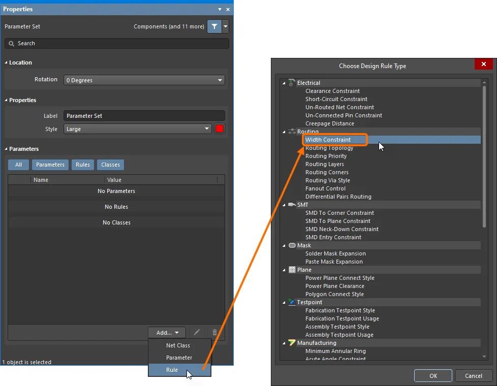
ルールの値を編集する。
Choose Design Rule Type ダイアログを使用して、ディレクティブにルールパラメータとして追加したいルールを選択します。ルールタイプをダブルクリックすると、対応する Edit PCB Rule (From Schematic) ダイアログにアクセスでき、その中でルールの制約を定義できます。
Edit PCB Rule (From Schematic) ダイアログに表示される具体的なプロパティは、選択した設計ルールに依存し、PCB エディタでそのルールに対して定義されているプロパティと同じになります。
たとえば、下図は Max-Min Width Rule 用の Edit PCB Rule (From Schematic) ダイアログを示しており、ここではすべての層に対する Min/Preferred/Max 設定を構成したり、各層ごとに各幅設定を手動で定義したり、あるいは Impedance Profile を使用することを選択できます。インピーダンスプロファイルを選択していて、PCB エディタ内ですでに実際の物理ボード構造が定義されている場合は、Load the PCB Layer Stack and calculate the track width values するためのボードファイルも選択できます。
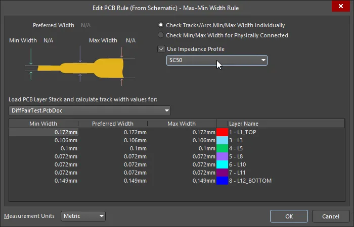 PCB が存在し、レイヤースタックが定義されている場合、計算された幅を回路図に読み込むことができます。
上記のルールは、ネットクラスに適用されました。これは、Blanket Directive を配置し、PCB Routing Directive を接続してネットをクラスにグループ化し、そのクラスに Max-Min Width Rule を適用することで実現しました(show image![]() )。
)。
各 PCB Design Rule と制約の詳細については、here をクリックしてください。
Measurement Units ドロップダウンフィールドを使用して、Metric または Imperial 単位を選択します。
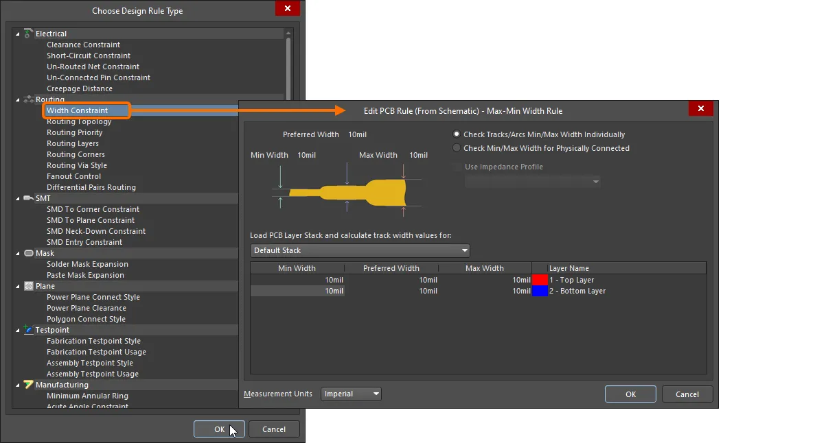
選択したルールに対して制約を指定します。
Parameters 領域のエントリには、選択したルールタイプと指定した制約が表示されます。次の画像は、Parameter Set ディレクティブに対して定義された幅制約ルールパラメータを示しています。デザイン空間内にルールを表示するには、Rules 領域内の可視性 ( ) アイコンをクリックします。
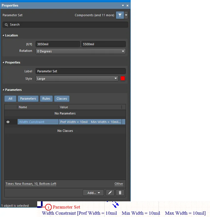
特定のネットに対して定義された複数のルール制約。Parameter Set ディレクティブによるものです。
設計が同期プロセスを通じて PCB に転送されると、ディレクティブに含まれる情報に基づいて、関連する設計ルールが作成されます。生成された各ルールの名前には、そのルールのソースを区別するために Schematic という語が使用されます。

PCB 側で生成された設計ルール。
同じ Parameter Set ディレクティブには複数のパラメータを追加できるため、よりすっきりとした回路図にすることができます。
Net Class ディレクティブの配置
Net Class ディレクティブを使用すると、回路図上でユーザー定義のネットクラスを作成できます。Net Class ディレクティブは、メインメニューから Place » Directives » Parameter Set コマンドを選択し、コマンドページの Tip #2 で指定されているように Parameter Set を Net Class ディレクティブとして定義することで配置できます。回路図から PCB を作成すると、Net Class ディレクティブ内の情報を使用して、PCB 上に対応する Net Class が作成されます。ネットをネットクラスのメンバーにするには、対象となるワイヤ、バス、またはシグナルハーネスに Net Class ディレクティブを接続し、そのディレクティブの ClassName パラメータを目的のクラス名に設定します。この機能を使用するには、プロジェクトオプションダイアログの Class Generation タブ で Generate Net Classes オプション (User-Defined Classes 用) を有効にしておく必要があります。
あるネットに対して Net Class ディレクティブが定義されている場合、その Parameter Set オブジェクトによって作成される PCB 設計ルールは、設計が PCB エディタに転送されるときにルールスコープが Net Class になります。配置済みの Parameter Set ディレクティブにクラスを追加し、その値を必要な PCB Net Class に設定することで、Net Class ディレクティブを作成できます。
Net Class は PCB エディタ内からも作成できますが、ネットの論理的な機能やグループ化は通常、回路図の方がはるかに明確であるため、回路図側からプロセスを駆動する方が理にかなっています。
設計が同期プロセスを通じて PCB に転送されると、ディレクティブに含まれる情報に基づいて、関連するネットクラスが作成されます。
Blanket オブジェクト に Net Class ディレクティブを接続して、その Blanket でカバーされている個々のネットをメンバーとするネットクラスを作成します。同じ Blanket に PCB Layout ディレクティブも接続されている場合、PCB Layout ディレクティブのルールパラメータは、各個別ネットではなく、そのネットクラスをターゲットにします。変更を PCB ドキュメントにインポートすると、(パラメータごとに) スコープがそのネットクラスをターゲットとする単一の設計ルールが作成されます。
Blanket ディレクティブの配置
Parameter Set ディレクティブは、それが接続されている特定のネットにしか適用できませんが、Blanket ディレクティブと組み合わせることで、そのスコープを Blanket 内のすべてのネットに拡張できます。
このタイプのディレクティブを配置するには、メインメニューから Place » Directives » Blanket コマンドを選択します。Blanket を配置する際には、単純な矩形形状か多角形形状のいずれかを定義できます。後者の方が、シート上の必要なネットオブジェクトのカバー範囲をより正確に制御できます。
Blanket は対象となるネットを識別します。これらのネットに設計要件を適用するには、Blanket のエッジ上の任意の場所に Parameter Set ディレクティブを配置します。Blanket ディレクティブの下にあるネットに周囲ディレクティブを適用するには、そのネットに関連付けられたオブジェクト (ピン、ポート、ネットラベル、パワーポート、ワイヤ/バス/ハーネスセグメント (両端を含む)) のいずれかが Blanket の境界内に入っている必要があります。ネットラベルなどのネット識別子については、ホットスポットが Blanket 内にある必要があることに注意してください。メンバーネットが期待どおりに PCB の Parameter Set に反映されない場合は、Blanket の領域を調整してみてください。
Blanket ディレクティブがどのネットに適用されるかを確認するには、
Net Colors 機能を使用してハイライトします。
View » Set Net Colors メニューから必要な色を選択し、対象の Blanket ディレクティブの周囲をクリックします。特定のネットのハイライトを解除するには、
View » Set Net Colors » Clear Net Color コマンドを使用し、色を削除したいネットをクリックします。すべての回路図シートからネットの色付けをクリアするには、
View » Set Net Colors » Clear All Net Colors コマンドを使用します。
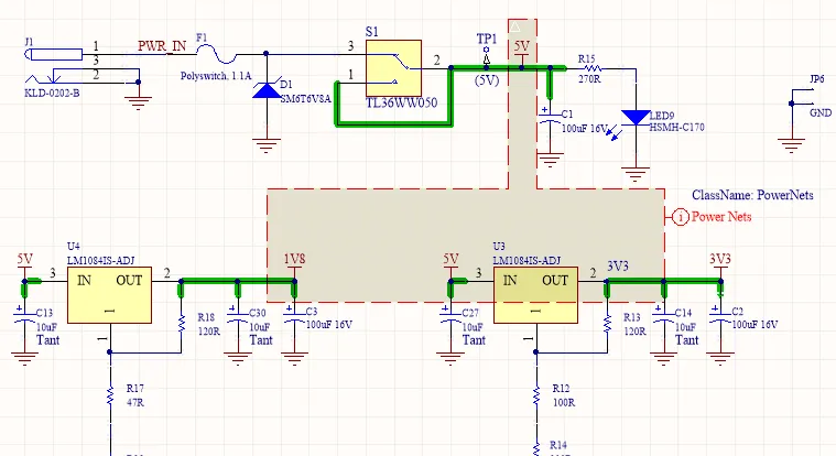
Blanket ディレクティブを使用して、Blanket 内のネットに Parameter Set ディレクティブを適用する例。
Blanket ディレクティブの使用例には、次のようなものがあります。
-
Blanket オブジェクトに Parameter Set ディレクティブを接続し、そのルールパラメータを Blanket でカバーされている各個別ネットに適用する。
-
Blanket オブジェクトに Parameter Set ディレクティブを接続し、そのメンバーが Blanket でカバーされている個々のネットとなる Parameter Set を作成する。
-
Blanket オブジェクトに Differential Pair ディレクティブを接続し、その Blanket の範囲内にある差動ネットに基づいて差動ペアオブジェクトを作成する。
Blanket オブジェクト に Parameter Set ディレクティブを接続して、そのルールパラメータを Blanket でカバーされている各個別ネットに適用します。同じ Blanket に Parameter Set ディレクティブも接続されており、その Parameter Set に Net Class パラメータも含まれている場合、Parameter Set ディレクティブのルールパラメータは、各個別ネットではなく、そのネットクラスをターゲットにします。変更を PCB ドキュメントにインポートすると、(パラメータごとに) スコープがそのネットクラスをターゲットとする単一の設計ルールが作成されます。
周囲の Parameter Set ディレクティブをコピーして、別の Blanket ディレクティブや個々のワイヤ、バス、ハーネスに接続することもできます。その結果、同じ Parameter Set ディレクティブに関連付けられたすべての追加ネットが、同じ生成された PCB Net Class に追加されます。
Blanket は Parameter Set ディレクティブと組み合わせることで、Blanket で定義された領域内に完全に含まれるコンポーネントに対して、コンポーネントクラスやパラメータを適用するためにも使用できます。これを行うには、Blanket に接続された Parameter Set ディレクティブのプロパティ内にある Component Class および Parameter オプションを、Add ボタンドロップダウンから使用します。コンポーネントクラスおよびパラメータに関する情報は、PCB 更新時の ECO プロセス中にプロジェクトの PCB ドキュメントへ転送されます。
Blanket
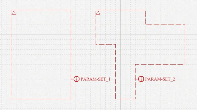
矩形の Blanket と多角形の Blanket – それぞれに Blanket ディレクティブが接続されています。
まとめ
Blanket は、ネットおよび/またはコンポーネントの集合の上に配置される、矩形または多角形のグループディレクティブオブジェクトです。Blanket に適用されたディレクティブ (Parameter Set オブジェクト) は、Blanket がカバーするすべてのネットおよびコンポーネントに適用されます。Blanket を配置する際には、単純な矩形形状か多角形形状のいずれかを定義できます。後者の方が、シート上の必要なネットオブジェクトのカバー範囲をより正確に制御できます。
Blanket は、次の条件を満たすすべてのネットに適用されます。
-
Blanket で定義された領域内に完全に含まれている、または
-
ワイヤ / バス / ハーネスの接続された端点頂点の少なくとも一方が Blanket の下にある、または
-
ワイヤ / バス / ハーネスにネットラベルが接続されており、そのネットラベルが Blanket の下にある。
コンポーネントについては、Blanket で定義された領域内にあるすべてのコンポーネントに適用されます。
Blanket の周囲 (Place » Directive) に適用されたディレクティブ (No ERC、Differential Pair、特定の Rule/Class Parameter Set など) は、Blanket オブジェクトによって登録されたすべてのネットおよびコンポーネントに適用されます。Blanket は 無効化および非表示 にすることができます。
利用可能性
Blanket は回路図エディタでのみ配置可能です。Blanket を配置するには、次のいずれかを行います。
-
メインメニューから Place » Directives » Blanket をクリックします。
-
デザイン空間上部にある Active Bar のディレクティブドロップダウン内の Blanket ボタン (
 ) をクリックします。Active Bar ボタンをクリックしたままにすると、関連する他のコマンドにアクセスできます。一度使用したコマンドは、そのセクションの Active Bar の最上部の項目になります。
-
回路図エディタ内で右クリックし、Place » Directives » Blanket をクリックします。
配置
長方形の Blanket を配置するには:
-
上記で説明したようにコマンドを起動します。
-
カーソルを配置し、左クリックするか Enter を押して、左上の角を配置します。
-
カーソルを配置し、左クリックするか Enter を押して、右下の角を配置します。
-
右クリックするか Enter を押して、配置を完了します。
-
続けて他の Blanket を配置するか、右クリックするか Esc を押して配置モードを終了します。
多角形状の Blanket を配置するには:
-
配置コマンドを起動します。
-
カーソルを配置し、左クリックするか Enter を押して、Blanket の開始点をアンカーします。
-
カーソルを配置し、左クリックするか Enter を押して、Blanket の形状を定義する一連のセグメントをアンカーします。
-
最後のセグメントを配置したら、右クリックするか Esc を押して配置を完了します。ポリゴンを「閉じる」必要はありません。ソフトウェアが開始点と最後に配置したセグメントを接続するために必要なセグメントを自動的に追加して形状を完成させます。
-
続けて他の Blanket を配置するか、右クリックするか Esc を押して配置モードを終了します。
Blanket セグメントの配置中に実行できる追加操作は次のとおりです:
-
Tab キーを押して配置を一時停止し、Properties パネルの Blanket モードにアクセスします。ここから線のプロパティをその場で変更できます。デザインスペースの一時停止ボタンオーバーレイ (
 ) をクリックして配置を再開します。
-
未確定のセグメントコーナーの曲がり方向を変更するには、 Spacebar を押します。
-
Blanket の多角形形状を定義しているときに、直前に確定したセグメントを削除するには Backspace を押します。続けて Backspace を使用すると、それ以前のセグメントが順に削除されます。
配置モードは、より細い点線で表されます。これは多角形状の Blanket を定義する際に特に有用です。これを利用して、さらにセグメントを確定する前に Blanket 全体の形状がどのようになるかを確認できます。複雑/自己交差する多角形形状はサポートされていません。ソフトウェアはそのような形状が形成されるのを防ぎます。
グラフィカル編集
この編集方法では、デザインスペース内で配置済みの Blanket オブジェクトを直接選択し、そのサイズ、形状、位置をグラフィカルに変更できます。Blanket オブジェクトを選択すると、次の編集ハンドルが使用可能になります:
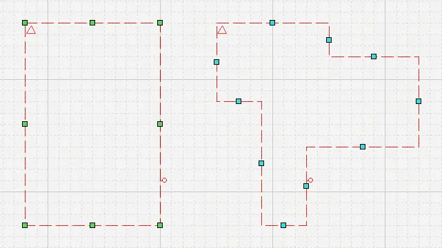 選択された長方形および多角形 Blanket と、そのグラフィック編集ハンドル。
セグメント中央の編集ハンドルをクリックしてドラッグすると、その辺を移動できます。
長方形 Blanket の場合、コーナーの編集ハンドルをクリックしてドラッグすると、垂直方向と水平方向の両方に同時にリサイズできます。
編集ハンドル以外の Blanket の外形線上をクリックしてドラッグすると、Blanket 全体を再配置できます。ドラッグ中に Blanket を回転または反転できます:
-
カーソル位置を中心として Blanket を反時計回りに回転するには、 Spacebar を押します。Shift+Spacebar は Blanket をカーソル位置を中心に時計回りに回転します。回転は 90° 単位で行われます。
-
カーソル位置を基準に、Blanket を X 軸方向または Y 軸方向に反転するには、 X または Y キーを押します。
多角形 Blanket の形状を変更した結果、複雑/自己交差形状になる場合、その変更は行えません。
Locked プロパティが有効なオブジェクトをグラフィカルに変更しようとすると、編集を続行するかどうかを確認するダイアログが表示されます。
Preferences ダイアログの
Schematic – Graphical Editing ページで
Protect Locked Objects オプションが有効であり、かつそのデザインオブジェクトに対して
Locked オプションも有効な場合、そのオブジェクトは選択もグラフィカル編集もできません。ロックされたオブジェクトをクリックして選択し、
List パネルで
Locked プロパティを無効にするか、
Protect Locked Objects オプションを無効にして、そのオブジェクトをグラフィカルに編集できるようにします。
非グラフィカル編集
利用可能な非グラフィカル編集方法は次のとおりです。
Blanket ダイアログまたは Properties パネルによる編集
Panel page: Blanket Properties
この編集方法では、関連する Blanket ダイアログモードおよび Properties パネルモードを使用して、Blanket オブジェクトのプロパティを変更します。
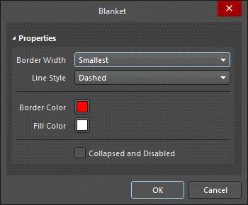
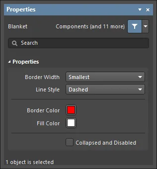 左側が Blanket ダイアログ、右側が Properties パネルの Blanket モード
配置後、Blanket ダイアログには次の方法でアクセスできます:
-
配置済み Blanket オブジェクトをダブルクリックします。
-
Blanket オブジェクト上にカーソルを置き、右クリックしてコンテキストメニューから Properties を選択します。
配置中に、Properties パネルの Blanket モードには Tab キーを押してアクセスできます。Blanket を配置し終えると、すべてのオプションが表示されます。
配置後、Properties パネルの Blanket モードには、次のいずれかの方法でアクセスできます:
-
Properties パネルがすでにアクティブな場合は、Blanket オブジェクトを選択します。
-
Blanket オブジェクトを選択した後、デザインスペース右下の Panels ボタンから Properties パネルを選択するか、メインメニューから View » Panels » Properties を選択します。
Blanket のプロパティには、配置モードに入る前に
Preferences ダイアログの
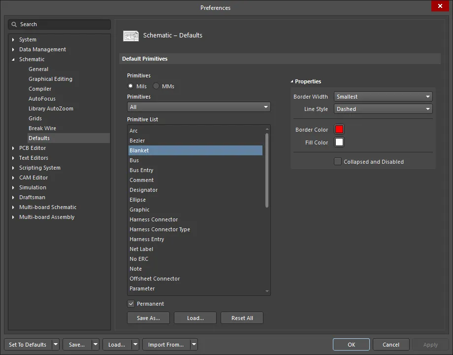
Schematic – Defaults ページからアクセスできます。これにより Blanket オブジェクトのデフォルトプロパティを変更でき、その後に配置する Blanket に適用されます。
Preferences ダイアログの
Schematic – Graphical Editing ページで
Double Click Runs Interactive Properties オプションが有効(デフォルト)な場合、プリミティブをダブルクリックするか、選択したプリミティブを右クリックして
Properties を選択すると、
Properties パネルが開きます。
Double Click Runs Interactive Properties オプションが無効な場合は、ダイアログが開きます。
ダイアログとパネルで利用できるオプションは同じですが、オプションの順序や配置は若干異なる場合があります。
複数オブジェクトの編集
Properties パネルは複数オブジェクトの編集をサポートしており、現在選択されているすべてのオブジェクトで同一のプロパティ設定を一括変更できます。同一タイプのオブジェクトを手動で選択した場合、Find Similar Objects ダイアログ経由、または Filter や List パネル経由で選択した場合、Properties パネルでアスタリスク (*) では表示されていないフィールドは、選択されているすべてのオブジェクトに対して編集できます。
List パネルによる編集
Panel pages: List Panels, SCH Filter
List パネルは、1 つ以上のドキュメントからのデザインオブジェクトタイプを表形式で表示し、オブジェクト属性の迅速な確認と変更を可能にします。適切なフィルタリング(パネルの Include オプションを使用してオブジェクトタイプを選択する、または該当する Filter パネルや Find Similar Objects ダイアログを使用する)と組み合わせることで、アクティブなフィルタの範囲に含まれるオブジェクトのみを表示できます。表示されたオブジェクトのプロパティは、List パネル内で直接編集できます。
フィルタリングサポート
論理クエリ式を使用して Blanket オブジェクトをターゲットにする際に特に有用なキーワードが 2 つ用意されています。これらは、Blanket のプロパティに基づいて Blanket をターゲットにするための他のキーワード群を補完するものです。
-
Collapsed – オブジェクトが折りたたまれている(Compile Mask をターゲットにする場合にも有用)ことを示します。このキーワードは、Query Helper を使用する際に SCH Functions - Fields カテゴリ内で見つけることができます。
-
IsBlanket – オブジェクトが Blanket であるかどうかをテストします。このキーワードは、Query Helper を使用する際に SCH Functions - Object Type Checks カテゴリ内で見つけることができます。
必要に応じて、設計内の Blanket をターゲットとして抽出するクエリ用の論理式を作成します。Blanket をターゲットにした論理クエリ式の例をいくつか示します:
IsBlanket And Collapsed – 現在折りたたまれているすべての Blanket オブジェクトをターゲットにします。
IsBlanket And Not Collapsed – 現在折りたたまれていないすべての Blanket オブジェクトをターゲットにします。
Blanket の無効化
配置後、左上の小さな三角形 ( ) をクリックすることで Blanket を一時的に無効化できます。1 回クリックすると Blanket が無効化され非表示になり、再度クリックすると再有効化されます。これにより、Blanket を設計から完全に削除することなく、その影響を制御する便利な方法が提供されます。
Blanket は、
Properties パネルで
Collapsed and Disabled オプションを有効にするか、
SCH List パネルで編集する際に
Collapsed オプションを有効にすることでも無効化できます。
Blanket Properties
Schematic Editor のオブジェクトプロパティは、配置されたオブジェクトの表示スタイル、内容、および動作を指定する定義可能なオプションです。各オブジェクトタイプのプロパティ設定は、次の 2 通りの方法で定義されます。
-
Pre-placement settings – ほとんどの Blanket オブジェクトプロパティ、または論理的に事前定義可能なプロパティは、Preferences ダイアログの Schematic - Defaults ページ(デザインスペース右上の
 ボタンからアクセス)で編集可能なデフォルト設定として利用できます。Primitive List 内でオブジェクトを選択すると、右側にそのオプションが表示されます。
-
Post-placement settings – デザイン空間で配置済みの Blanket を選択すると、Blanket ダイアログPropertiesパネルの両方で、すべての Blanket オブジェクトのプロパティを編集できます。


Preferences ダイアログ
Schematic - Graphical Editing ページの
Double Click Runs Interactive Properties オプションが無効(デフォルト)になっている場合、プリミティブをダブルクリックするか、選択したプリミティブを右クリックして
Properties を選択すると、ダイアログが開きます。
Double Click Runs Interactive Properties オプションが有効になっている場合は、
Properties パネルが開きます。
ダイアログとパネルでオプションの内容は同じですが、オプションの順序や配置は若干異なる場合があります。
以下のオプション一覧では、Preferences ダイアログ内でデフォルト設定としては利用できないオプションには「Properties パネルのみ」と記載しています。
Properties
-
Border Width - ドロップダウンを使用して、希望する枠線の太さを選択します。
-
Line Style - ドロップダウンを使用して、希望する線種を選択します。
-
Border Color - カラーボックスをクリックして、枠線に使用する色を選択します。
-
Fill Color - カラーボックスをクリックして、塗りつぶしに使用する色を選択します。
-
Collapsed and Disabled - チェックして Blanket を折りたたみ、無効化します。
間接(パラメータベース)ディレクティブ
Parameter Set ディレクティブは、パラメータを保持できない Schematic 上のデザインオブジェクトをターゲットにする場合に必要ですが、パラメータを保持できるオブジェクトに対しては、関連する回路図オブジェクトにパラメータとして追加(および定義)することで、デザインディレクティブを間接的に適用できます。要するに、それらは parameter-based directives です。
パラメータベースのディレクティブの使用例としては、特定コンポーネントの高さを制限する、またはデザイン内のすべてのオブジェクトを対象とするクリアランス制約を追加する、といったものが挙げられます。制約を定義するために必要なパラメータは、ルールとしてオブジェクトに追加されます。
PCB と同期すると、回路図上のオブジェクトに追加されたパラメータベースのディレクティブは PCB デザインルールになります。対応する PCB デザインルールのスコープは、最初にパラメータが割り当てられたオブジェクトの種類によって決定されます。次の表は、サポートされている回路図パラメータから PCB ルールスコープへの対応をまとめたものです。
いずれの場合も、ルールベースのパラメータを追加する方法は同じです。各タブまたはダイアログから、次の操作を行います。
-
パラメータをルールとして追加します。
-
使用するルールタイプを選択します。
-
選択したルールタイプの制約を設定します。
回路図上のオブジェクトにデザインルールパラメータを追加すると、それぞれのルールパラメータに一意の ID が付与されます。同じ ID が、PCB 上に作成される対応するデザインルールにも付与されます。この Unique ID により、ルールの制約は回路図側または PCB 側のどちらからでも編集でき、同期時に変更内容を反映させることができます。
コンポーネントクラスの指定
同様の考え方で、ターゲットとなるコンポーネントに ClassName パラメータを追加し、その値を目的のクラス名に設定することで、回路図上でコンポーネントクラスを定義できます。デザインを PCB に転送すると、定義されたコンポーネントクラスが作成されます。
回路図で定義した Component Classes を PCB に反映させるには、Project Optionsダイアログ内で次のオプションを設定する必要があります。
-
ダイアログの Class Generation タブの User-Defined Classes 領域にある Generate Component Classes オプションを有効にします。
-
ダイアログの Comparator タブで、Differences Associated with Components » Extra Component Classes Mode 設定を
Find Differences に設定します。
上記の Class Generation タブオプションは、下図に示されています。画像にカーソルを重ねると、Comparator タブオプションの設定が表示されます。
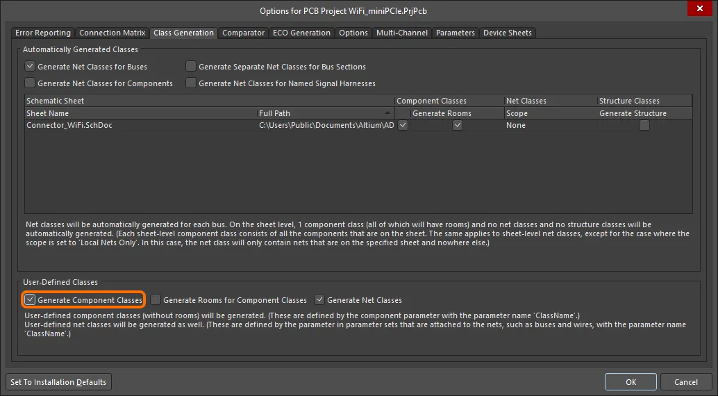
Component Classes を PCB に反映させるには、Class Generationタブで Generate Component Classes オプションを有効にします。画像にカーソルを重ねると、Extra Component Classes Mode 設定を Find Differences に設定する必要がある Comparator タブが表示されます。
一度定義されたクラスは、該当コンポーネントのプロパティにある Propertiesパネルの Properties 領域でロックできます。
PCB エディタでは、1 つのコンポーネントが複数の Component Classes に属することができます。これを回路図で定義するには、回路図コンポーネントパラメータ値内で、各 PCB Component Class 名をカンマで区切って入力します(画像を表示![]() )。
)。
ディレクティブの印刷制御
デフォルトでは、すべてのデザインディレクティブが回路図シートの印刷に含まれますが、これは変更可能です。
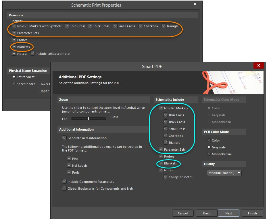
必要に応じてディレクティブの印刷を制御します。No ERC ディレクティブについては、特定のシンボルスタイルのみを印刷し、他を除外することができます。


 AI で翻訳