Draftsmanは専用のファイル形式(*.PCBDwf)でPCB図面ファイルを作成し保存します。
新しいDraftsmanドキュメントの作成
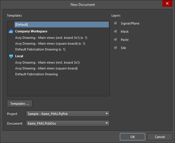
新しいDraftsmanドキュメントを作成するには、メインメニューからFile » New » Draftsman Documentコマンドを使用するか、必要なプロジェクトのエントリを右クリックしてProjectsパネルでAdd New to Project » Draftsman Documentコマンドをコンテキストメニューから選択します。開かれるNew Documentダイアログでは、事前定義されたドキュメントテンプレートまたは[Default]オプションを選択して、空白のA4ドキュメントを作成できます。

指定されたプロジェクトとPCBから空白またはテンプレートベースのDraftsmanドキュメントを作成します。
ワークスペーステンプレート(接続されたワークスペースのエントリの下にリストされ、形式は<TemplateName> (v.<Revision>))では、利用可能な各テンプレートの最新のリビジョンが使用されます。 ボタンをクリックしてPreferencesダイアログのData Management – Templatesでアクセスします。
Draftsmanの「スマート」ドキュメントテンプレートは、指定されたPCB図面ビューと情報テキストでドキュメントを自動的に埋めるように設定できます。ドキュメントテンプレートが最初に作成されるとき、現在のシートテンプレートを使用してページのプロパティ(サイズ、スタイル、マージンなど)を定義できます。
Draftsmanシートおよびドキュメントテンプレートの作成についての詳細は、Draftsmanテンプレートの作成ページを参照してください。
希望のドキュメントテンプレートとともに、特定のProject (Altium Designerで複数のプロジェクトが開かれている場合)および選択したプロジェクト内で見つかったPCBソースDocumentを選択できます。新しいドキュメントは指名されたプロジェクトに追加され、そのプロジェクトからデータを引き出すことになり、アクティブなプロジェクトになります。
ダイアログのLayersチェックボックスは、製造ドキュメントテンプレートが使用される場合にドキュメント内で製造図面を生成するために使用される基板レイヤー(Signal/Plane、Mask、Paste、および/またはSilk、レイヤースタックによって定義される)を決定します。製造図面は、選択されたテンプレートで対応するboard fabricationビューのLayerがAll (for document template)に設定された場合、シートごとに1つ作成されます。
PCBとDraftsmanを同期させる
DraftsmanはPCBの銅、コンポーネント、および機械レイヤーから直接設計データを抽出します。PCBデータが変更された場合、ドキュメント上の任意の場所を右クリックしてコンテキストメニューからImport Changes From <PCBDocumentName>.PcbDocを選択するか、メインメニューからTools » Import Changes From <PCBDocumentName>.PcbDocコマンドを選択して、Draftsman内のデータを更新できます。

同じ名前の異なるフットプリントはDraftsmanドキュメントで区別されるため、同じ名前を持つフットプリントのいくつかが異なる構造を持っている場合、あるコンポーネントのフットプリントへの変更が同じ名前のフットプリントを持つすべてのコンポーネントに伝播されないことに注意してください(例えば、board assemblyビュー上で)。
一般的なドキュメントオプション
デザインスペース内でオブジェクトが選択されていないときにPropertiesパネルのGeneralタブで定義される全体のDraftsmanドキュメント(複数のシート/ページで構成される可能性があります – 詳細を学ぶ)の設定は、ドキュメントのソース設計データ、グラフィックスタイル、描画動作、および適用される単位を決定します。設定の変更は、適用されたドキュメントテンプレートによって定義されたデフォルトのプロパティ設定を上書きします。
ドキュメントオプションはドキュメント全体に適用されるのに対し、Page Optionsは個々のドキュメントページ(シート)に適用されることに注意してください。ドキュメントオプションとシートプロパティは、現在のDraftsmanドキュメントおよび/または保存されたドキュメントテンプレートに保存されます。
| オプション |
説明 |
General ( ) )
|
Grid Size,
Show Grid |
これらのオプションを使用して、ドキュメントのグリッドを設定します。詳細については、グリッドとスナッピングオプションの設定セクションを参照してください。 |
Snapping,
Snapping Distance |
スナッピング機能を設定するには、これらのオプションを使用してください。詳細については、グリッドとスナッピングオプションの設定セクションを参照してください。 |
| Document Font |
ドキュメントシートで使用される基本フォントスタイルと追加属性を設定します。これにより、board assemblyビューのタイトルなどの描画オブジェクトに適用されるドキュメントレベルのフォントが定義されます。オブジェクトのプロパティパネルを使用して、個々のオブジェクトのドキュメントレベルのフォントを上書きすることができます。 |
| Sheet Border |
ドキュメントシートのゾーン境界線と文字色を設定します。 |
| Sheet Color |
ドキュメントシートの背景色を設定します。 |
Variants Display,
Pattern,
Not Fitted Text,
Not Fitted Font,
Font Size (Min/Max) |
これらのオプションを使用して、ボードアセンブリビューで選択したデザインバリアントに対して未装着として設定されたコンポーネントの表示を構成します。詳細については、Board Assemblyビューのページを参照してください。 |
Source ( ) )
|
| PCB Document |
ドラフトマン文書のデータソースとして使用されるボードデザインを設定します。ドロップダウンメニューを使用して、現在のプロジェクトにある利用可能なPCB文書から選択します。 |
| Variants |
ドロップダウンメニューを使用して、ドラフトマン文書のデータソースとして使用されるボードデザインのバリエーション(バリアント)を選択します。詳細については、デザインバリアントのサポートセクションを参照してください。 |
| Scale |
現在のドキュメントに配置された新しいフルボードビュー(board assemblyビュー、board fabricationビュー、またはdrill drawingビューなど)のサイズを設定します。配置されたビューのスケールを制御する方法については、ビューの操作ページを参照してください。 |
Line Styles ( ) )
|
| Dash Pattern |
破線オプションの線/間隔定義は、0.02mm単位(メトリックモードの場合)です。例えば、パターン値20,10,20は、0.4mm、0.2mm、0.4mmのダッシュ配置を繰り返し、サイクル長は1mm(50単位)です。カスタム破線オプションは ボタンを使用して作成でき、 ボタンを使用して作成でき、 ボタンで削除できます。 ボタンで削除できます。 |
| Line Thicknesses |
利用可能なラインスタイルオプションの重さまたは厚さ。デフォルト値を復元するには、 ボタンを使用してください。 ボタンを使用してください。 |
Units ( ) )
|
| Units |
文書の主要な測定単位の種類を設定します。
ステータスバーの左端にある座標のエントリを見れば、アクティブな主要ユニットをすぐに確認できます。 ( ). ).
|
| Dual Units |
ドキュメントの二次(デュアル)測定単位タイプを設定します。追加のデュアル単位は、描画オブジェクトのPropertiesパネルで有効にできます。 |
| Decimal Separator |
ドロップダウンメニューから小数点区切りに使用する文字を選択してください。 |
| Remove Leading Zero |
値が"1"未満のときに先頭のゼロを自動的に削除できるようにします。例えば、"0.5"はこのオプションが有効な場合、".5"として表示されます。ASME Y14.5 Dimensioning and Tolerancingでは、インチ単位を使用する際に、1未満の値については先頭のゼロを省略することが規定されています。 |
| Primary Units |
|
| Dual Units |
|
ドラフトマン文書パラメータ
デザインスペースでオブジェクトが選択されていないとき、PropertiesパネルのParametersタブは、現在のドキュメントで利用可能なパラメータの表形式リストビューを表示します。プロジェクト(バリアントを含む)、システム、PCB、および追加されたカスタムパラメータがリストに表示されます。

独自のカスタムパラメータを作成または削除するには、 および
および ボタンを使用します。
カスタムパラメータ名は一意でなければなりません。プロジェクトまたはバリアントレベルのパラメータ(デザインスペースでオブジェクトが選択されていないときのPropertiesパネルのGeneralタブのSource領域で選択されたバリアント)がある場合、同じ名前のカスタムパラメータを作成することはできません。プロジェクトまたはバリアントレベルのパラメータが、Draftsmanドキュメントで同じ名前のパラメータを定義した後に作成された場合、そのドキュメントに対してドキュメントレベルのパラメータが最優先されます。ドキュメントレベルのパラメータがない場合、バリアントレベルのパラメータ値が同じ名前のプロジェクトレベルのパラメータ値を上書きします。
リストに表示されるパラメータエントリの範囲を設定するために、リストの下部にあるチェックボックスを使用します: (プロジェクト)、
 (システム)、
 (PCB)。プロジェクト、システム、およびPCBパラメータエントリは読み取り専用であり、追加されたカスタムパラメータは編集可能で常にリストに含まれます。
以下は、事前定義されたシステムおよびPCBパラメータです。
システムパラメータ
| パラメータ |
説明 |
Application_BuildNumber |
現在のAltium Designerインストールのバージョンとビルド番号。 |
BOMPageNumber |
Titleフィールドの部品表テーブルプロパティで、現在のBOMテーブルページ番号を表示します。 |
BOMTotalPages |
Titleフィールドの部品表テーブルプロパティで、BOMテーブルの総ページ数を表示します。 |
ComponentName |
Titleフィールドのcomponentビュープロパティで、ビューが作成されたコンポーネントのコメントを表示します。 |
CurrentDate |
システム設定から自動的に計算される現在の日付。 |
CurrentTime |
システム設定から自動的に計算される現在の時刻。 |
DocumentFullPathAndName |
Draftsmanドキュメントファイルの完全なパスと名前。例:C:\MyTestDesign\Kame_FMU_asm_rm.PCBDwf。 |
DocumentName |
ファイルパスを除いたDraftsmanドキュメントのファイル名のみ。例:Kame_FMU_asm_rm.PCBDwf。 |
DocumentScale |
Draftsmanドキュメントに選択されたスケール。 |
DocumentUnits |
Draftsmanドキュメントに選択された測定単位。 |
FootprintName |
Titleフィールドのcomponentビュープロパティで、ビューが作成されたコンポーネントのフットプリント名を表示します。 |
HoleName |
Titleフィールドのcounter holeビュープロパティで、ビューが作成されたパッド(その指定子、PCB上の位置、および層に関して)の名前を表示します。 |
ModifiedDate |
Draftsmanドキュメントファイルの変更日時スタンプ;自動的に入力されます。 |
ProjectName |
Draftsmanドキュメントの親プロジェクトの実際の名前(拡張子を含む)。例:Sample - Kame_FMU.PrjPcb。 |
Revision |
デフォルトのドキュメントレベルパラメータRevisionに指定された値を表示します。 |
SheetNumber |
特別な文字列として配置された場合、Draftsmanドキュメントの現在のシート番号を表示します。 |
SheetNumber_OneSheet |
特別な文字列として配置された場合、Draftsmanドキュメントの現在のシート番号を表示します。Draftsmanドキュメントにシートが1枚しか含まれていない場合は値を表示しません。 |
SheetTotal |
Draftsmanドキュメントの総シート数。 |
VersionControl_PCBDocumentRevNumber |
DraftsmanドキュメントのソースPCBの現在のリビジョン番号。この文字列に情報を含めるにはバージョン管理を使用する必要があります。 |
VersionControl_PCBDocumentRevNumberShort |
現在のリビジョン番号の短いGitハッシュ形式(最初の8文字)およびDraftsmanドキュメントのソースPCBのVCSステータス。この文字列に情報を含めるにはバージョン管理を使用する必要があります。 |
VersionControl_PrjFolderRevNumber |
プロジェクトの現在のリビジョン番号で、プロジェクトファイルを含むプロジェクトの完全なコミットが実行されるたびに増分されます。この文字列に情報を含めるにはバージョン管理を使用する必要があります。 |
VersionControl_PrjFolderRevNumberShort |
プロジェクトの短いGitハッシュ形式(最初の8文字)アイテム |
VersionControl_RevNumberShort |
ドラフトマン文書の現在のリビジョン番号の短いGitハッシュ形式(最初の8文字)とVCSステータス。この文字列に情報を含めるには、バージョン管理を使用する必要があります。 |
ViewLabel |
board sectionビューまたはboard detailビューのプロパティのTitleフィールドで使用され、ビューに適用されたLabelを表示します。 |
ViewLayerName |
board fabricationビューのプロパティのTitleフィールドで使用され、ビューが作成されたLayerを表示します。 |
ViewScale |
ビューのプロパティのTitleフィールドで使用され、ビューの選択されたScaleを表示します。 |
ViewSide |
board assemblyビュー、board fabricationビュー、componentビュー、またはboard isometricビューのプロパティのTitleフィールドで使用され、ビューが作成されるためのView Side / Face sideを表示します。 |
ViewVariantName |
board assemblyビューまたはboard isometricビューのプロパティのTitleフィールドで使用され、ビューが作成されたVariationを表示します。 |
PCBパラメータ
| オプション |
説明 |
Arc_Count |
ドラフトマン文書のソースPCBにおけるアークオブジェクトの数。 |
BoardArea |
ドラフトマン文書のソースPCBの面積は、ドラフトマン文書に選択された主要な測定単位で表示されています。 |
BoardDensity |
ドラフトマン文書のソースPCBの密度。 |
BoardHeight |
ドラフトマン文書のソースPCBの高さは、ドラフトマン文書に選択された主要な測定単位で表示されています。 |
BoardWidth |
ドラフトマン文書のソースPCBの幅は、ドラフトマン文書に選択された主要な測定単位で表示されています。 |
BlindVia_Count |
ドラフトマン文書のソースPCB上のブラインドビアの数。 |
BuriedVia_Count |
ドラフトマン文書のソースPCB上の埋め込みビアの数。 |
Component_Count |
ドラフトマン文書のソースPCBにおけるコンポーネントオブジェクトの数。 |
ComponentMixed_Count |
ドラフトマン文書のソースPCB上の混合パッド(SMDとスルーホールの両方)を持つコンポーネントの数。 |
ComponentsArea |
ドラフトマン文書のソースPCBのコンポーネントエリアは、ドラフトマン文書に選択された主要な測定単位で表示されています。 |
ComponentSMD_Count |
ドラフトマン文書のソースPCB上のSMDパッドを持つコンポーネントの数。 |
ComponentThru_Count |
ドラフトマン文書のソースPCB上のスルーホールパッドを持つコンポーネントの数。 |
ComputerName |
ドラフトマン文書が作成されたコンピュータのシステム名。 |
CopperInner_Weight_Max |
内層の銅の最大重量。 |
CopperOuter_Weight_Max |
外層の銅の最大重量。 |
Fill_Count |
ドラフトマン文書のソースPCBにおけるフィルオブジェクトの数。 |
Hole_Count |
ドラフトマン文書のソースPCBにおけるパッド/ビアホールの数。 |
Hole_Size_Min |
ドラフトマン文書のソースPCBにおける最小穴径は、ドラフトマン文書に選択された主要な測定単位で示されています。 |
Hole_Size_Num |
ドラフトマン文書のソースPCBにおけるユニークな穴の直径の数。 |
Item |
プロジェクトリリーサを使用してプロジェクトのソースデータが公開された最新のPCBプロジェクト設計アイテムの名前。例:SRC-Sample - Kame_FMU。 |
ItemRevision |
プロジェクトリリーサを使用してプロジェクトのソースデータがリリースされた最新のPCBプロジェクトデザインアイテムのアイテムリビジョン。例:01.A.1。 |
ItemRevisionBase |
プロジェクトリリーサを使用してプロジェクトのソースデータがリリースされた最新のPCBプロジェクトデザインアイテムのアイテムリビジョンのベースレベル部分。例:1。 |
ItemRevisionLevel1 |
プロジェクトリリーサを使用してプロジェクトのソースデータがリリースされた最新のPCBプロジェクトデザインアイテムのアイテムリビジョンのレベル1部分。例:A。 |
ItemRevisionLevel2 |
プロジェクトリリーサを使用してプロジェクトのソースデータがリリースされた最新のPCBプロジェクトデザインアイテムのアイテムリビジョンのレベル2部分。例:01。 |
Layer_Count |
ドラフトマン文書のソースPCB上の銅層の数。 |
MicroVia_Count |
ドラフトマン文書のソースPCB上のマイクロビアの数。 |
Net_Count |
ドラフトマン文書のソースPCB内のネットの数。 |
Pad_Count |
ドラフトマン文書のソースPCB上のパッドオブジェクトの数。 |
Pcb_File_Name |
ドラフトマン文書のソースPCBファイルの完全なパスと名前。例:C:\MyTestDesign\Kame_FMU.PcbDoc。 |
Pcb_File_Name_No_Path |
ドラフトマン文書のソースPCBファイル名のみ(ファイルパスなし)。例:Kame_FMU.PcbDoc。 |
PCBConfigurationName |
Releaseビューで定義されたデータセットの名前(プロジェクトリリーサ)。 |
PadSMD_Count |
ドラフトマン文書のソースPCB上のSMDパッドの数。 |
PadThru_Count |
ドラフトマン文書のソースPCB上のスルーホールパッドの数。 |
Poly_Count |
ドラフトマン文書のソースPCB上のポリゴンプアオブジェクトの数。 |
SlotHole_Count |
ドラフトマン文書のソースPCB上のスロット穴を持つパッドオブジェクトの数。 |
SolderMask_Bottom |
ボトムはんだマスクの有無。ボトムはんだマスク層がない場合、パラメータはNo mask値を持ちます。ボトムはんだマスク層があるがその色が定義されていない場合、パラメータはNo color値を持ちます。ボトムはんだマスク層があり、その色が定義されている場合、パラメータは色を示し、その名前(Green、Black、Blue、Redなど)またはRGBAコード(例:#FF0065FF)で表示されます。 |
SolderMask_Top |
トップはんだマスクの有無。トップはんだマスク層がない場合、パラメータはNo mask値を持ちます。トップはんだマスク層があるがその色が定義されていない場合、パラメータはNo color値を持ちます。トップはんだマスク層があり、その色が定義されている場合、パラメータは色を示し、その名前(Green、Black、Blue、Redなど)またはRGBAコード(例:#FF0065FF)で表示されます。 |
SquareHole_Count |
ドラフトマン文書のソースPCB上の長方形の穴を持つパッドオブジェクトの数。 |
StackedVia_Count |
ドラフトマン文書のソースPCB上のスタックドビアの数。 |
String_Count |
ドラフトマン文書のソースPCB上のテキストオブジェクトの数。 |
Thru_Via_Count |
ドラフトマン文書のソースPCB上のスルーホールビアの数。 |
Total_Thickness |
ドラフトマン文書のソースPCBの総厚さ。 |
Track_Count |
ドラフトマン文書のソースPCB上のトラックオブジェクトの数。 |
VariantName |
ドラフトマン文書に選択されたデザインバリアントの名前。 |
Via_Count |
ドラフトマン文書のソースPCB上のビアオブジェクトの数。 |
グリッドとスナッピングオプションの設定
ドラフトマン文書にオブジェクトを配置する前に、グリッドを設定し、スナッピングオプションを構成して、配置を容易にします。グリッドとスナッピングオプションは、デザインスペースでオブジェクトが選択されていない場合のPropertiesパネルのGeneral領域のGeneralタブで構成されます。

デザインスペースでは、グリッドラインは点線として表示され、各10番目のグリッドラインは実線として描画されます。ドキュメント内でオブジェクトが選択されていないときに、PropertiesパネルのGrid Sizeフィールドを使用してグリッドライン間の測定距離を設定します。あるいは、メインメニューからView » Set Grid Sizeコマンドを選択することでアクセスできるSnap Grid (1..1000)ダイアログ( )を使用してグリッド値を設定することもできます(ショートカット:
G)。
ドキュメントシートで表示グリッド線を制御するには、Show_Gridオプションを使用します。デザインスペースでグリッドの色を指定するには、関連する色ボタンを使用してください。
スナッピングは、ドラフツマン文書のシート上にオブジェクトを配置したり移動したりする際の補助機能です。この機能は、既存のオブジェクトや文書の定義されたグリッドによって生成されたポイントやガイドにプリミティブを引き寄せます。これにより、文書のページ上のさまざまな要素を迅速かつ簡単に整列させることができます。スナッピングは、PropertiesパネルのSnappingオプションやメインメニューのView » Toggle Snappingコマンド(ショートカット:Shift+E)を使用して有効化/無効化できます。
ステータスバーからスナッピング機能の状態をすぐに確認できます。そこにはSnapping: EnabledまたはSnapping: Disabled と表示されます。( ).
).
スナッピング機能が有効になっている場合、以下のオプションを個別に有効/無効にすることでさらに設定できます。
| オプション |
説明 |
| Snap to Grid |
有効にすると、プレビューカーソルはオブジェクト配置モードの間、グリッドラインの交差点にスナップ(ジャンプ)します。グリッドが表示されていない場合(つまり、Show_Gridオプションが無効になっている場合)には、グリッドへのスナップは機能しないことに注意してください。 |
| Snap to Vertices |
有効にすると、プレビューカーソルはオブジェクト配置モードの間にオブジェクトの角(頂点)にスナップします。プレビューカーソルが頂点にスナップすると、オレンジ色の点で頂点が強調表示されます。 |
| Snap to Boundaries |
有効にすると、プレビューカーソルはオブジェクト配置モードの間、オブジェクトの周囲線(またはそのエッジの延長)にスナップします。オブジェクトの周囲の延長は細い破線として表示されます。 |
| Snap to Line centers |
有効にすると、プレビューカーソルはオブジェクト配置モードの間にオブジェクトの周囲線の中点にスナップします。プレビューカーソルが中点にスナップすると、オレンジ色の点で中点が強調表示されます。 |
| Snap to Circle centers |
有効にすると、プレビューカーソルはオブジェクト配置モードの間、円オブジェクトの半径中心にスナップします。プレビューカーソルが円の中心点にスナップすると、オレンジ色の点で中心点が強調表示されます。 |
| Snap to component references |
有効にすると、プレビューカーソルはコンポーネントの参照ポイントにスナップします。 |
| Snap to Visible primitives |
有効にすると、プレビューカーソルはシートの現在のビューに表示されているオブジェクトプリミティブにスナップします(他のスナップオプションによって決定されます)。無効にすると、カーソルはシート上に存在するすべてのオブジェクトにスナップします。 |
Snapping Distanceオプションを使用して、プレビューカーソルがスナップターゲットとして指定された要素にスナップする距離を入力します。あるいは、ドロップダウンを使用して現在のグリッドに対する値を選択します(例:0.5x Snap Grid)。
ドキュメントシート(ページ)の設定
ドキュメント内のDraftsmanドキュメントは複数のシート形式であり、それぞれのページ(シート)が特定のボードプロジェクトの生産情報に割り当てられるようになっています。
現在のドキュメントにシートを追加したり削除したりすることが、Add New SheetコマンドやRemove Sheetコマンドを使って、Toolsメインメニューやデザインスペースの右クリックメニューから行えます。新しいシートは、コマンドを実行したときにカーソルが位置しているシートの後に挿入され、直前のシートに適用されているDraftsmanシートテンプレートに従って表示されます。
Draftsmanドキュメントのシートは、ブックマークパネルを使用して追加、削除することができ、シートの順序を変更することもできます – 詳細を学ぶ。
Draftsmanドキュメント内の個々のページ(シート)の設定は、デザインスペースでオブジェクトが選択されていないときにPropertiesパネルのPage Optionsタブで定義できます。これらの設定は、ページの基本構造(サイズ、余白など)を決定します。

ページオプションのプロパティに加えられた変更は、現在のページに適用することも、ドキュメント内のすべてのページに適用することもできます。 ボタンを選択してプロパティパネルの上部にある変更されたプロパティ設定を現在のシートに適用するか、
 ボタンを適用してドキュメントのすべてのシートに変更を適用します。現在のページの番号は表示され、Current Pageドロップダウンから選択できます。
パネルのFormatting and Size領域を使用して、ページ形式がどのように定義されるかを選択できます。
| オプション |
説明 |
| Template |
利用可能なDraftsmanシートテンプレートの範囲から選択してページサイズと形式を設定します。ワークスペーステンプレート(<TemplateName> (v.<Revision>)のエントリの下にリストされている)の場合、利用可能な各テンプレートの最新のリビジョンが使用されます。
-
現在選択されているテンプレートを再適用するには、 ボタンを使用します。古いワークスペーステンプレートの場合、これによりテンプレートの最新のリビジョンが適用されます。 ボタンを使用します。古いワークスペーステンプレートの場合、これによりテンプレートの最新のリビジョンが適用されます。
-
ドキュメントテンプレートでページプロパティがシートテンプレートによって定義されている場合、そのシートテンプレートがその間に変更されている場合は再適用する必要があります。
-
ハードドライブ上のシートテンプレートを参照して選択するには、Sourceフィールドの右にある ボタンを使用します。 ボタンを使用します。
|
| Standard |
シートサイズを標準のページ形式に設定します。Sheet_Sizeドロップダウンメニューを使用して、標準ページ寸法のリストから選択します。 |
| Custom |
指定されたカスタム寸法を使用してシートサイズを設定します。WidthおよびHeightフィールドを使用します。入力できる最大の幅または高さの値は20000 mmです。 |
パネルのMargin and Zones領域のオプションは、シートの境界グラフィックとそのゾーン区分のサイズを定義します。
| オプション |
説明 |
| Show Zones |
境界グラフィックにゾーン区分を表示するように設定します。 |
| Vertical |
縦のシート余白における区分(行)の数を設定します。アルファベット-数字のゾーンラベリングタイプは、このパネルの領域にあるOriginおよびLetter Positionの設定によって定義されます。 |
| Horizontal |
横のシート余白における区分(列)の数を設定します。アルファベット-数字のゾーンラベリングタイプは、このパネルの領域にあるOriginおよびLetter Positionの設定によって定義されます。 |
| Margin |
ページの端と各四つの境界線の間の距離を設定します。 |
| Origin |
ドキュメントシートのどの角からペリメーターゾーンのアルファベット-数字指標が始まるかを設定します(ゾーン位置A-1または1-A)。 |
| Letter Position |
ドキュメントシートに配置される文字ゾーンインジケーターの位置を設定します:水平周辺ゾーン(列)または垂直ゾーン(行)です。すべての文書シートで列に割り当てられた英数字インジケーターが順次増加するように、Iterate Columns Across Sheetsオプションをチェックします(各シートでAまたは1から始めるのではなく)。
|
ブックマークパネルを使用して製図文書をナビゲートする
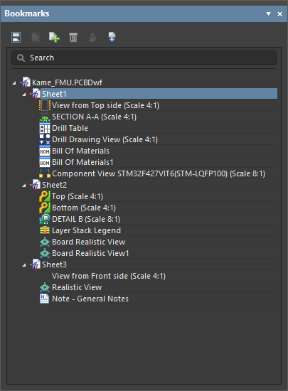
Bookmarksパネルは、マルチシートのドラフツマン文書をナビゲートし管理する便利な方法を提供します。このパネルは、Projectsパネルに似た完全な文書構造の展開可能なツリービューを表示し、すべての文書シートとそれらのシート内の主要なビューオブジェクトを含んでいます。

Bookmarksパネルを使用して、マルチシートのドラフツマン文書内のビューをナビゲートします。
Bookmarksパネルは、ドラフツマン文書内のシートとオブジェクトの構造化されたツリービューを提供し、各シートエントリは展開および折りたたむことができます。ツリー内のシートエントリは、ドラフツマンによって降順で自動的に名前が付けられます。パネル内の各シートエントリのサブコンテンツには、そのシート上のドラフツマンビュータイプのオブジェクトが含まれますが、寸法、コールアウト、グラフィックシェイプなどの二次描画オブジェクトは含まれません。
Bookmarksパネルは、ツリーで選択されたシートまたは図面オブジェクトがデザインスペースでフォーカスされるアクティブなナビゲーション機能を提供します。ツリーで選択されたオブジェクトは、図面ビューでも選択され、そのオブジェクトに合わせてズームされます。ツリービューのナビゲーションは双方向であるため、デザインスペースで選択されたシートやオブジェクトに応じて、自身の選択が変更されます。

ドキュメントシートを管理するための追加機能がBookmarksパネルに含まれており、シートの追加や削除、ドラフトマンドキュメント構造内での位置順の変更が可能です。パネルの上部にある一連の機能ボタンは、ドキュメントシートの表示と構造を管理するために使用されます:
シートやツリー内のオブジェクトで右クリックコンテキストメニューを使用することで、追加のオプションにアクセスできます。
-
シートを右クリックして、選択したシートを削除したり、ドキュメントに新しいシートを追加したり、プロパティパネルでそのプロパティにアクセスしたりできます。Propertiesパネルは、まだ開いていない場合は開きます。
-
選択したオブジェクトを削除するか、プロパティパネルでそのプロパティにアクセスするには、オブジェクトの右クリックオプションを使用してください。Propertiesパネルは、まだ開いていない場合は開きます。
ブックマークパネルに表示される構造は、出力ジョブの対応する出力コンテナのPDF settingsダイアログでGenerate Table of Contentsオプションを有効にすることにより、PDF出力にブックマークとして含めることができます。詳細を見る。
Support for Design Variants
Altium Designerでは、ボードデザインのバリエーション(デザインバリアント)を作成し、このバリアント情報をDraftsmanに渡すことができます。これにより、配置された図面ビューにデザインバリエーションを適用できるようになります。各バリアントにはパラメータを追加できます。これらのパラメータは通常、現在有効なバリアントを示すためにAltium Designer文書内で特別な(解釈された)文字列として適用されます。
Draftsmanでは、設計スペース内でオブジェクトが選択されていない場合、PropertiesパネルのGeneralタブのProperties領域にあるVariantsドロップダウンを使用して、ドキュメントレベルでのプロジェクトの現在のバリアント選択が行われます。

配置された board assemblyビュー、board isometricビュー、およびboard realisticビュー は、選択されたバリアントを反映します。ボード組み立てビューの場合、設定されたドキュメントオプションに従って、取り付けられていないコンポーネントのレンダリングが適用されます(詳細を見る)。ボード等角ビューやボードリアルビューの場合、取り付けられていないコンポーネントはビューに表示されません()。ビューが設計スペースで選択されている場合、ビューの現在のバリアントはプロパティパネルで選択できます。
バリアントの選択は、個々のビューごとに上書きすることができます。したがって、Draftsmanドキュメントには、それぞれ異なるバリアントに設定された複数の配置ビューが存在することがあります。
特別な文字列、例えば=VariantNameやバリアントパラメーターは、自由文字列として図面に配置することができます。
テキストオブジェクトについての詳細は、図面注釈ページを参照してください。

より汎用的な解決策として、特別な文字列をDraftsmanシートテンプレートのタイトルブロックに含めることができます。
Draftsmanドキュメントの基本バリアント([No Variations])が選択されている場合、ドキュメントに配置されたバリアントパラメーターの特別な文字列は解釈されません。その後、ドキュメントに基づいて出力ジョブファイルから生成される出力では、OutJobで選択されたバリアントに従ってパラメーター特別文字列が解釈されます – 詳細を見る。