PCB エディタはグリッドベースのデザイン環境です - デザインオブジェクトは配置、またはスナップグリッドと呼ばれるものに配置されます。複数のスナップグリッドを定義することができ、必要に応じて指定した領域に制限することができます。スナップグリッドには優先順位があり、現在位置で利用可能なグリッドの中で最も優先順位の高いグリッドが自動的に適用されます。スナップグリッドは、コンポーネントまたは非コンポーネントに制限することもできます。
また、スナップガイドは自由に配置でき、オブジェクトの位置合わせに便利なビジュアルアイコンとなります。
このページでは、PCB ドキュメントでスナップグリッドとスナップガイドを設定する方法を説明します。
スナップグリッドやスナップガイドと同様に、PCB エディタには、デザインオブジェクトの正確な位置や整列を助けるために設計された、いくつかの追加スナップ機能があります。これらの機能は、Unified Cursor-Snap System と呼ばれています。詳細は、Working with the Cursor-Snap Systemページを参照してください。
インペリアルグリッドかメートルグリッドか?
伝統的に、グリッドはコンポーネントのピンピッチとボードに使用する予定の配線技術に合わせて選択されていました。基本的な考え方は、製造コストを下げ、信頼性を向上させるために、トラックとクリアランスの両方をできるだけ広くすることです。もちろん、トラックとクリアランスの選択は、最終的には各設計で何が達成できるかによって決定されます。
時間の経過とともに、部品とそのピンのサイズは劇的に縮小し、ピンの間隔も狭くなっています。部品の寸法とピンの間隔は、主にスルーホールピンのインペリアル寸法から、表面実装ピンのメートル寸法に移行することが多くなりました。新しい基板設計を始める場合、既存の(インペリアルの)製品に適合する交換用基板を設計するなどの強い理由がない限り、メトリックで作業する方がよいでしょう。なぜか?なぜなら、旧式のインペリアル・コンポーネントには大きなピンがあり、ピン間に余裕があるからです。一方、小型の表面実装デバイスはメートル法で製造されます。これらは、製造/組み立て/機能する製品が動作し、信頼できることを保証するために高い精度を必要とするものです。また、PCBエディタはオフグリッドピンへの配線を簡単に扱うことができるため、メートル基板上でインペリアル部品を使用する作業も負担になりません。
ユーザー定義グリッド
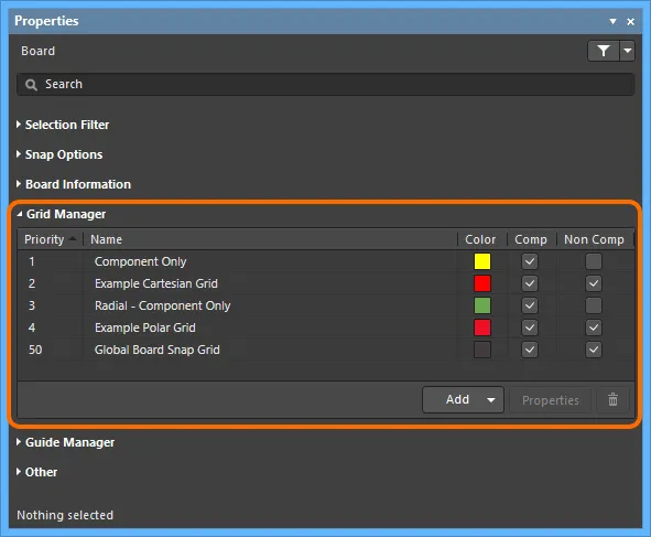
任意の数のユーザ定義グリッドは、Properties パネルのGrid Manager領域(デザインスペースで現在選択されているデザインオブジェクトがない時にアクセス)から実行される全てのグリッド管理でデザインスペース用に設定できます。利用可能なコントロールを使用して、カスタムローカルグリッドを定義し、デザインオブジェクト(特にコンポーネント)をより正確に配置することができます。

PropertiesパネルのGrid Manager領域は、ボードで使用するグリッドを定義し、整理するための中心的なコマンドです。
グリッドタイプ
ソフトウェアは2つのカスタムグリッドタイプの作成をサポートします:デカルト(伝統的な垂直/水平グリッド)とポーラー(円形グリッド)です。
-
Cartesian Grid- Add Cartesian Gridコマンド(前述の  ボタンから利用可能)を使用して、このタイプの新しいグリッドを作成します。新しいグリッドのエントリがリストに表示され、最初はNew Cartesian Gridというデフォルト名で表示されます。グリッドを編集するには、そのエントリをダブルクリックするか、エントリを選択して
 ボタンをクリックします。Cartesian Grid Editorダイアログが開き、グリッドを定義するためのオプションが表示されます。
 CartesianGrid Editorダイアログを使用した直交グリッドの定義と、その結果のデザイン空間での表示例。
カルテジアングリッドエディタダイアログのオプションとコントロール
デフォルトのグローバルスナップグリッドでは、Settings、Steps、Display領域だけがダイアログに表示されます。
設定
-
Name- 意味のある名前を入力します。例えば、グリッドの目的を反映した形式を使用してグリッドの名前を付けることができます(例:Grid for Component-Side Memory)。
-
Unit- グリッドの測定単位をImperialまたはMetric指定します。
-
Rotation- グリッドを(指定した原点を中心に)回転させるかどうか、またその量を指定します。
ステップ
デフォルトでは、2つのフィールドは、フィールドの右のボタン に描かれた連続した鎖で示されるようにリンクされています。この状態では、Step Xフィールドに指定したものはすべてコピーされ、Step Yフィールドに使用されます。このリンクを解除してステップ・サイズを個別に入力するには、チェーン・リンクをクリックします。リンクが切れたチェーン -
 - が表示され、Step Yフィールドが編集可能になります。
PCB デザインスペース内から直接、X/Y ステップサイズを定義できる以下のコントロールもあります。それぞれのケースで、2 つの '計算' 位置を指定するためにデザインスペースに移動し、結果のステップサイズはそれに応じて計算されます。
-
Set Step X in PCB View- 結果のサイズは、デザインスペースで選択したポイントによって形成される三角形の斜辺として取得されます。
-
Set Step Y in PCB View- 結果のサイズは、デザイン空間で選択されたポイントによって形成される三角形の斜辺として取得されます。
-
Set Step X from Delta X- 結果のサイズは、X 座標の差だけを使用して取得されます。
-
Set Step Y from Delta Y- 結果のサイズは、Y座標の差だけを使用して取得されます。
-
Set Both Steps from Delta- 結果のサイズは、XとY座標の差だけを使用して取得されます。
Step Y が Step Xに続いている時(チェーンが "リンク "されている時)、Set Step X in PCB ViewとSet Step X from Delta Xコントロールだけが利用可能であることに注意してください。
原点
-
Show Origin- デザイン空間に原点マーカーを表示します。
-
Origin X- デザイン空間のグリッドの中心点のX座標を指定します。
-
Origin Y- デザイン空間でのグリッドの中心点のY座標を指定します。
-
Set Origin in PCB View- グリッドの原点の中心点を定義するためにクリックする PCB デザイン空間に移動します。結果の座標値は、Origin XとOrigin Yフィールドに読み込まれます。
表示
-
Fine- 関連するドロップダウンを使用して、デザインスペースでグリッドの細かいレベル表示に使用するマーカーを、Lines、Dots、Do Not Draw のいずれかに定義します。細かいレベルの表示グリッドを使用しない場合は、Do Not Drawを選択します。マーカーに使用されるステップサイズは、Steps領域で定義されたものです。関連する色見本をクリックすると、標準のChoose Colorダイアログが表示され、デザインスペースのファインレベル表示グリッドに使用する色を指定できます。また、Reset to Defaultボタンを使って色をデフォルトに戻すこともできます。
-
Coarse-デザインスペースのグリッドの粗レベル表示に使用されるマーカーを定義するために、関連するドロップダウンを使用してください。選択肢は、Lines、Dots、またはDo Not Drawです。粗レベル表示グリッドを使用したくない場合は、Do Not Drawを選択してください。粗レベル表示グリッドは、Multiplierフィールドで選択されたエントリーに応じてステップサイズが増加した、細レベル表示グリッドです。関連するカラースウォッチをクリックすると、デザインスペースの粗レベル表示グリッドに使用する色を指定できる標準のChoose Colorダイアログにアクセスできます。細レベル表示グリッドに使われている色とは全く異なる色を選ぶことができます。また、細レベル表示グリッドに現在使用されている色の明度を素早く明るくしたり暗くしたりするには、LighterまたはDarkerボタンをクリックしてください。
Reset to Defaultボタンをクリックしたときに、FineおよびCoarse表示グリッドに割り当てられるデフォルトの表示色は、View Configurationパネル(ショートカットL) のSystem Colors領域で定義されます。
-
Multiplier- このフィールドを使用して、グリッドのステップ・サイズの必要な倍数(
2x Grid Step、5x Grid Step、または10x Grid Step)を指定します。
エクステント
デフォルトでは、2つのフィールドはリンクされていて、フィールドの右のボタンに描かれている連続した鎖で示されています -

。この状態では、
Widthフィールドに指定したものはすべてコピーされ、
Heightフィールドに使われます。このリンクを解除して個別に値を入力するには、このチェーンリンクをクリックします。ボタンは壊れた鎖を表し -

-、
Heightフィールドが編集可能になります。
PCB デザインスペース内から直接、幅や高さを定義できるコントロールもあります。それぞれの場合、2つの '計算' 位置を指定するためにデザインスペースに移動し、それに応じて幅や高さが計算されます。
-
Set Width in PCB View- 結果の幅は、デザインスペース内の選択したポイント間の X 座標の差だけを使用して取得されます。
-
Set Height in PCB View- 結果の高さは、デザイン空間で選択したポイント間の Y 座標の差だけを使用して取得されます。
-
Set Width and Height in PCB View- 結果の幅と高さは、X と Y 座標の差だけを使用して取得されます。
HeightがWidthに続いている(チェーンがリンクしている)場合、Set Width in PCB Viewコントロールだけが利用可能であることに注意してください。
象限
この領域を使って、グリッドがどの象限を占めるかを指定する。グリッドの領域は、ダイアログのExtents領域のWidthとHeightの設定によって定義されるように、有効なすべての象限で同じになります。

Quadrants領域オプションの使用例。1,2,4象限だけが使用可能で、結果のグリッドはグリッドの原点に対してこれらの象限だけを占めることに注意。
-
Polar Grid- Add Polar Gridコマンド(前述したように  ボタンから利用可能)を使用して、このタイプの新しいグリッドを作成します。新しいグリッドのエントリがリストに表示され、最初はNew Polar Gridというデフォルト名で表示されます。グリッドを編集するには、そのエントリーをダブルクリックするか、そのエントリーを選択して、
 ボタンをクリックします。Polar Grid Editorダイアログが開き、グリッドを定義するためのオプションが表示されます。
 Polar Grid Editorダイアログを使った極座標グリッドの定義とデザインスペースでの表示例。
極グリッドエディタダイアログのオプションとコントロール
設定
-
Name - このフィールドを使用して、極グリッドに意味のある名前を付けます。例えば、グリッドの目的を反映した書式を使用して名前を付けることができます(例:
Grid for Component-Side Memory)。
-
Unit - このフィールドを使用して、グリッドに使用する測定単位を指定します:インペリアル またはメトリック。
ステップ
-
Angular Step- このフィールドを使用して、角度グリッド線間の距離を度単位で定義します。この値は、定義された角度範囲にわたって角度グリッド線を均等に配置するために使用されます。
-
Radial Step- このフィールドを使用して、半径方向のグリッド線間の距離を定義します。必要なステップサイズを直接入力するか、関連するドロップダウンリストから一般的なサイズを選択します。
-
Set Radial Step in PCB View- PCB デザインスペース内から直接ラジアルステップを定義するためにクリックします。2つの '計算' 位置を指定するためにデザインスペースに移動します - 結果のステップサイズは、デザインスペースで選択した点によって形成された三角形の斜辺として取得されます。
原点
-
Origin X - グリッドの中心点のX座標を指定します。
-
Origin Y- グリッドの中心点のY座標を指定します。
-
Set Origin in PCB View- グリッドの原点の中心点を定義するためにクリックできる PCB デザイン空間に移動するために、このコントロールをクリックします。結果の座標値は、Origin XとOrigin Yフィールドにロードされます。
表示
-
Fine - 関連するドロップダウンを使用して、デザインスペース内のグリッドの細かいレベル表示に使用するマーカーを、Lines、Dots、またはDo Not Draw のいずれかで定義します。マーカーに使用されるステップサイズは、Steps 領域で定義されたものです。関連する色見本をクリックすると、標準のChoose Colorダイアログが表示され、デザインスペースの細かいレベル表示のグリッドに使用する色を指定できます。粗いレベルの表示グリッドを使用したくない場合は、Do Not Draw オプションを選択します。また、Reset to Defaultリンクを使用して、色をデフォルトに戻すこともできます。
-
Coarse - 関連するドロップダウンを使用して、デザインスペースのグリッドの粗いレベルの表示に使用するマーカーを定義します(Lines、Dots、Do Not Drawのいずれか)。粗いレベルの表示グリッドは、Multiplier フィールドで選択した項目に従ってステップ・サイズが大きくなった細かいレベルの表示グリッドになります。粗いレベルの表示グリッドを使用したくない場合は、Do Not Drawオプションを選択します。関連する色見本をクリックすると、標準のChoose Colorダイアログが表示され、デザインスペースの粗いレベルの表示グリッドに使用する色を指定できます。細かいレベルの表示グリッドに使用する色とは全く異なる色を自由に選択できます。また、LighterまたはDarkerのリンクを使用して、粗いレベルの表示グリッドに現在使用されている色の明るいまたは暗い色合いをすばやく採用することもできます。また、デフォルトにリセットリンクを使用して、色をデフォルトに戻すこともできます。
-
Multiplier - このフィールドを使用して、グリッドのステップ・サイズの必要な倍数(2x Grid Step、5xGrid Step、10xGrid Step)を指定します。
角度範囲
-
Start Angle- このフィールドを使用して、極グリッドがどの角度から始まるかを設定します。
-
End Angle- このフィールドを使用して、ポーラーグリッドがどの角度で終了するかを設定します。
開始角度と終了角度が同じ数値に設定されている場合、ダイアログは自動的にStart Angle00.000、End Angle360.000に更新されます。極グリッドは360°フルに表示されます。
半径範囲
-
Min - このフィールドを使用して、極座標グリッドの最小直径を設定します。
-
Max - このフィールドを使用して、極座標グリッドの最大直径を設定します。
Radial Rangeの直径は、原点から外側に向かって測定され、グリッドの半径方向の範囲を設定します。
そのグリッドを使用しているボードの領域にカーソルを合わせ(コマンドを起動する前にデザインスペースでクリックしないでください)、Ctrl+Gキーボードショートカットを押すか、G キーボードショートカットを使用し、その後のポップアップメニューでGrid Propertiesエントリを選択することで、デザインスペースで定義されたグリッドの関連エディタに素早くアクセスできます。
デフォルトスナップグリッド
デフォルトのスナップグリッドは、Global Board Snap Grid という名前でボードに定義されます。これは、専用のローカルグリッドによってカバーされていないボードの領域でオブジェクトの配置と移動のために使用されるグリッドです。デフォルトグリッドは、ボード形状上に表示されるだけであっても、常にデザインスペース全体に適用されることに注意してください。
 Global Board Snap Grid - カスタムローカルグリッドが定義されていないボードのどの領域でも使用されます。
デフォルトのグリッドは、デカルトタイプのグリッドです。グリッドのステップサイズや表示は変更できますが、グリッドの名前の変更、無効化、削除はできません。
デフォルトのスナップグリッドのサイズ変更、測定単位、およびスナップグリッドの上書き
.
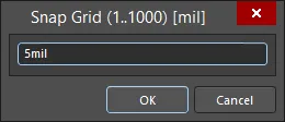
デザインスペース内で、Gキーボードショートカットは、デフォルトのGlobal Board Snap GridX(水平)またはY(垂直)ステップ値を素早く設定するコマンドのメニューにアクセスできます。これらのコマンドは、ボードのデフォルトスナップグリッドにのみ 影響し、定義したカスタムグリッド(デカルトや極座標)には影響しません。コマンドは、他の定義済みのステップサイジングに素早く切り替えるか、または特定のカスタムサイジングを定義できるSnap Grid (1..1000)ダイアログ(ショートカット:Ctrl+Shift+G)にアクセスするために利用可能です。

Snap Grid(1..1000)ダイアログ
事前定義値/カスタム値の適用は、XおよびYステップ値を同時に設定するか、XまたはYステップ値を個別に設定するかによって異なります:
-
XとYのステップ値を同時に設定-Global Board Snap Gridの Step Xと Step Yプロパティが以前にリンクされていなかった場合、このコマンドは2つをリンクし、両方を同じ定義済み/カスタム値に設定します。
-
XまたはYステップ値を個別に設定-Global Board Snap Gridの Step Xと Step Yプロパティが以前にリンクされていた場合、このタイプのコマンドは2つのリンクを解除し、選択した(XまたはY)ステップ値のみを定義済み/カスタム値に設定します。他のステップ値は以前の設定のままです。
単位を指定せずにスナップグリッド設定を入力すると、PropertiesパネルのBoardモードのOther領域のUnits設定によって決定された、デザインで選択されたデフォルトの測定単位で入力されます。このダイアログで値(mm または mil)を入力する際に単位を指定すると、現在デフォルトでない場合、ドキュメントのデフォルトの測定単位が変更されます。
現在カーソルの下にあるグリッド(デフォルトまたはカスタムローカル)の現在のスナップグリッド設定は、常に現在の原点からの相対的なカーソル位置と共にステータスバーに表示されます。グリッドが(ステップXとステップYの両方に対して)グローバルに設定されている場合は、グリッドの値が1つだけ表示されます。グリッドがステップXまたはステップYに対して個別に設定されている場合は、個々のグリッドステップが表示されます。
絶対原点は、デザイン空間の左下(0,0)です(100X x 100Yインチが最大)。
 ステータスバーには、常に現在のスナップグリッドとカーソル位置が表示されます。
Status Barは、オブジェクトホットスポットスナップの現在の状態も表示します。オブジェクトのホットスポットスナップは、エレクトリカルオブジェクト、特にデフォルトのGlobal Board Snap Grid や、定義されたカスタムグリッドに該当しないオブジェクトのルーティングを補助します。これは、カーソルがオブジェクトから離れていても、オブジェクトのホットスポット(例えば、パッドの中心)にスナップできる距離(範囲)を与えます。オブジェクトのホットスポットスナップはスナップグリッドをオーバーライドするので、グリッド外のオブジェクトに簡単に接続できます。Shift+Eキーボードショートカットを使用して、3つのモード(Off、Current Layer、All Layers)を切り替えます。詳しくは、オブジェクトスナッピングを参照してください。
デザインスペースでデフォルトのGlobal Board Snap Gridの細かいレベル表示に使用するマーカーを線と点の間で切り替えるには、メインメニューからView » Grids » Toggle Visible Grid Kindコマンドを選択します。
グリッドの目的の定義
ローカルグリッドは様々な状況で使用できる:
-
コンポーネント以外のオブジェクトを配置する場合。
-
コンポーネントオブジェクトの配置のみ。
-
非コンポーネントオブジェクトとコンポーネントオブジェクトの両方の配置において。
グリッドの使用方法(目的または用途)の定義は、次の表に従って、Properties パネルのGrid Manager領域のグリッドのエントリに関連付けられた CompおよびNon Comp オプションを使用して実行されます:
| |
NON COMP = クリア |
NON COMP = 有効 |
| COMP = クリア |
グリッドは表示されないが、現在のスナップ動作設定<に/a>従って適用される。 |
グリッドは表示され、すべての非コンポーネントオブジェクトのアクションに適用されます。 |
| COMP = 有効 |
コンポーネントのアクションでのみグリッドが表示され、適用されます。 |
グリッドは、すべての種類のオブジェクトのアクションで表示および適用されます。 |
 CompオプションとNon Comp オプションを使用して、ローカルグリッドの適用を決定します。
.
次のアニメーションは、PCB エディタでコンポーネントを配置するためにローカルの Polar Grid を使用する例を示しています。グリッドはコンポーネントのみで使用するために定義されているため、コンポーネントが移動し始める時のみ表示されます。この例は、極座標グリッドの優れた機能である自動配置回転も示しています。このタイプの定義されたグリッド上でコンポーネントを移動すると、グリッドの周りを移動するにつれて、自動的にグリッドの原点に回転します。この機能を、標準的なオブジェクトの回転(Spacebar (反時計回り)、Shift+Spacebar(時計回り))と組み合わせて使用すると、コンポーネントを必要な位置に正確に配置できます。
 コンポーネントのみのローカルPolar Gridにコンポーネントを配置した例。
[/collapse]
グリッド表示の定義
Global Board Snap Gridと同様に、定義したカスタムグリッドに対して、グリッドをデザインスペースでどのように表示するかをコントロールするオプションが提供されています。2つのレベルを定義できます:
 デザイン・スペースに表示されたファイン・レベルとコース・レベルの表示グリッドを持つデカルト・グリッドの例。左:細かいレベルはドットで、粗いレベルは線で表示。右:細かいレベルと粗いレベルの両方のグリッドがLinesを使って表示されている.
グリッドエディタでReset to Defaultリンクをクリックすると、FineおよびCoarse表示グリッドの色を指定したデフォルトの色にリセットできます。デフォルトのカラーリングは、View ConfigurationパネルのView Optionsタブにある General Settings領域で定義します。Show Gridオプションの右にある色見本をクリックし、表示されるカラーパレットから必要な色を選択します。この1つのデフォルト色は、FineとCoarseの両方の表示グリッドに使用されることに注意してください。また、ここで色を変更すると、デフォルトのGlobal Board Snap Gridにのみ影響することに注意してください。既存のカスタムグリッドはそれらに設定された表示色を保持し、Reset to Defaultリンクが使用された場合のみ、この新しい色に戻ります。
ネスティングとグリッドの優先順位
Properties パネルのGrid Manager領域で定義したローカルグリッドは、ボード領域内で自由に積み重ねることができます。それに応じて原点座標を指定することによって、グリッドは重ねることができ、ボードをレイアウトするときにデザインオブジェクトの配置を微調整するグリッドの入れ子階層を作成することができます。
グリッドの競合(重なり合ったグリッドの中でどのグリッドにデザインオブジェクトをスナップさせるか)は、優先度システムを使用して解決されます。あなたが作成し定義した各ローカル配置グリッドには、番号が付けられた優先順位が与えられます。デフォルトでは、各新規グリッドには最高の優先度1が与えられ、それに応じてすべての既存グリッドは優先度を下げられます。
Global Board Snap Gridは例外です。これは、定義されたカスタムグリッドによって'カバー'されていないボードのすべての領域で使用されるデフォルトのグリッドなので、優先度設定50が与えられています。
デザイン空間では、優先順位は描画順序によって区別されます。最も優先度の高いグリッド(優先度1)は他のグリッドの前に描画され、次に優先度2のグリッドが描画され、そしてデフォルトのGlobal Board Snap Gridまで描画されます。
 3つのネストされたPolarグリッドの例。黄色の極座標グリッドが最も優先度が高く、一番上に表示されます。赤の極グリッドは次の優先順位で、黄色のグリッドの後ろに表示されますが、水色のグリッドの前に表示されます。すべてのカスタムグリッドが優先順位で優先されるため、デフォルトグリッドはこれらすべてのグリッドの後ろに表示されます。
Global Board Snap Gridの優先順位は変更できません。常に50の優先順位に固定されています。
グリッドの無効化
特定のデザインオブジェクトの配置や移動中にグリッドが不要になる場合があります。グリッドを削除するのではなく(ボードの同じまたは異なる領域で後で再び必要になるかもしれないので)、デザインスペースで'隠す'ことができます。これは、Properties パネルのGrid Manager領域でグリッドの関連するCompとNon Comp属性を無効にすることで実現できます。
 ローカルグリッドを無効にすると効果的に非表示になり、オブジェクトがグリッドにスナップできなくなります。ネストされたグリッドの例では、Red Polarグリッドが無効になっています。グリッドは削除されていないので、再定義することなく、必要なときに再度有効にして使用することができます!
デフォルトのGlobal Board Snap Gridは、永久に有効です。これは、ボードの領域にローカルグリッドが定義されていないときに使用されるデフォルトグリッドだからです。しかし、View ConfigurationパネルのView OptionsタブのGeneral Settings領域のShow Gridオプションを無効にすることによって、このグリッドとすべての定義されたグリッドを非表示にすることができます。
グリッドの削除
カスタムグリッドは、Properties パネルのGrid Manager領域で対応するエントリを選択し、 ボタンをクリックすることで削除できます。削除の確認を求められます。Yesをクリックしてください。
デフォルトのGlobal Board Snap Gridは削除できないことを覚えておいてください。
スナップガイド
Snap Guides は、オブジェクトやコンポーネントの配置を補助するために、特定の軸やポイントにカーソルスナップを駆動する目的で手動で配置される特別なオブジェクトです。また、一般的なレイアウトや位置合わせのための視覚的なインジケータとしても機能します。以下のタイプのスナップガイドがサポートされています:
-
リニアガイド- 水平、垂直、+/-45°のラインスタイルのガイド。
-
ポイントガイド- ポイントスタイルのガイドで、オブジェクトの配置をより細かくコントロールできます。定義されたグリッドの範囲内で手動でマークされるホットスポットです。
デザインスペースにスナップガイドをいくつでも定義でき、配置と管理のコントロールはPropertiesパネルのGuide Manager領域から行えます(デザインスペースでデザインオブジェクトが選択されていない時にアクセスします)。この領域から( ボタンから)新しいスナップガイドを追加するコントロールもありますが、デザインスペースに直接(
 ボタンから)視覚的に追加し、必要に応じて微調整する方がはるかに簡単です。
スナップガイドは、Place » Work Guidesから利用できるコマンドを使用して配置することもできます。
スナップガイドはスナップグリッドと同じように動作します。カーソルは、オブジェクトが移動しているときに通過するガイドにスナップします。
 Propertiesパネルの Guide Manager領域は、デザインスペースで使用するビジュアル配置ガイドを管理するコマンドの中心です。これらは、オブジェクトの配置を補助するために利用できる様々なスナップガイドの例です。
配置や移動のようなインタラクティブな処理中、カーソルは、ガイドが定義されたグリッドと交差するポイントで、配置されたリニアガイドにスナップします。リニアガイドを使用すると、オブジェクトがガイドラインに対して「スナップ」するまでドラッグすることで、素早く整列させることができます。ポイントガイドの場合、移動するオブジェクトのホットスポットがガイドの近くを通過すると、ガイドに「スナップ」します。
グリッド表示がドットに設定されていると、ポイントガイドを視覚的に見つけやすくなります。
ガイドの無効化
特定のデザインオブジェクトを配置または移動する際に、スナップガイドが不要な場合があります。ガイドを削除するのではなく(ボードの同じエリアまたは別のエリアで後で再び必要になる可能性があるため)、デザインスペースで「隠す」ことができます。これは、Properties パネルの Guide Manager領域でガイドの関連するEnabled属性を無効にすることで実現できます。
 スナップガイドを無効にすると効果的に非表示になり、オブジェクトがスナップできないようになります。この画像では、+45 と -45 ガイドが無効になっています。ガイドは削除されていないので、再定義することなく、必要なときに再度有効にして使用することができます!
ガイドの削除
スナップガイドを削除するには、PropertiesパネルのGuide Manager領域でそのエントリを選択し、 ボタンをクリックします。削除の確認を求められます。Yesをクリックしてください。