Orienting and Positioning the 3D Model
Once the MCAD model has been placed near the component footprint, it can be positioned. It is common that a 3D MCAD model will need to be reoriented to suit the footprint.
There are a number of tools and features to help with this process.
Generally, it is easy to perform rotation tasks in 3D display mode, and X-Y positioning tasks, such as aligning a Snap Point with a location on the footprint, in 2D display mode.
Reference Point and Snap Points
Reference and Snap Points provide a way of holding a 3D Body object during placement. If the Snap to Center option is enabled in the PCB Editor – General page of the Preferences dialog, the cursor will automatically snap to the nearest vertex/reference point/snap point when you click and hold to move the object.
Generic models will have a reference point assigned in the MCAD software in which they were designed.
Snap points are user-defined locations, which allow the object to be held at that location as it is moved in the design space. Snap points are typically assigned to an edge or corner of the object or a center location, for example, the center of a pin or mounting peg. Snap points are used as reference markers on 3D objects and can be useful when orienting or aligning the 3D Body with primitives or other snap points on the PCB or PCB аootprint. Snap points can be added to any 3D Body, regardless of model type - extruded, cylinder, sphere, linked/embedded models (STEP, Parasolid, SOLIDWORKS), or a 3D model referenced from a Workspace.
Snap points can be added by entering the X, Y & Z locations in the Snap Points region of the Properties panel or they can be added interactively using the Add Snap Points From Vertices command. It is easier to interactively add Snap points in 3D mode.
To add snap points:
-
Press 3 to switch to 3D layout mode.
-
Select the Tools » 3D Body Placement » Add Snap Points From Vertices command.
-
As shown on the Status bar, the next step is to Pick the STEP model to add snap points to; click to select the required 3D Body object. The cursor will change to the 3D positional cursor (blue, six-pointed).
The Add Snap Points From Vertices command has two modes (use the Spacebar to toggle between the modes):
-
Click on a single vertex to add a snap point at that location, or
-
Click on two separate vertices; the snap point is added midway between them. Use this technique to add a snap point to the middle of a component pin.
-
Press the Spacebar to select the required mode.
-
Click a vertex to define the snap point location. Move the 3D cursor over the surface of the 3D model. When coming within close proximity of a local vertex, the 3D cursor will be magnetically pulled to that vertex.
-
If the two-click mode is being used, click a second vertex to define the second location; the snap point will be created midway between the two click locations.
-
Continue placing snap points or right-click or press Esc to terminate the command.
The snap points added to the chosen model will appear listed in the Snap Points section when viewing the properties for the selected model in the Properties panel.
Visibility controls for the 3D Body Reference Point and Custom Snap Points are located in the System Colors region of the View Configuration panel.
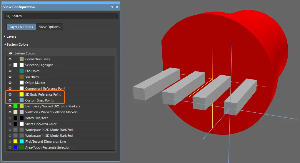
To remove Snap Points from vertices of a chosen 3D Body, choose the Tools » 3D Body Placement » Remove Snap Points command from the main menus. Position the cursor over the 3D model of interest and click, then move the 3D cursor over the surface of the 3D model. The 3D cursor will only move between existing snap points. With the 3D cursor over a snap point, click to remove that snap point.
Center Snapping for 3D models
To improve the convenience and accuracy of adding Snap Points to a 3D model, the following points are automatically snapped to, during Snap Point definition:
-
All hole centers.
-
The 90° locations (points crossing the orthogonal axes) around a hole circle.
-
The middle of a border line.
-
The model’s body axis.
-
The center point in a line between two snap points (Spacebar mode).
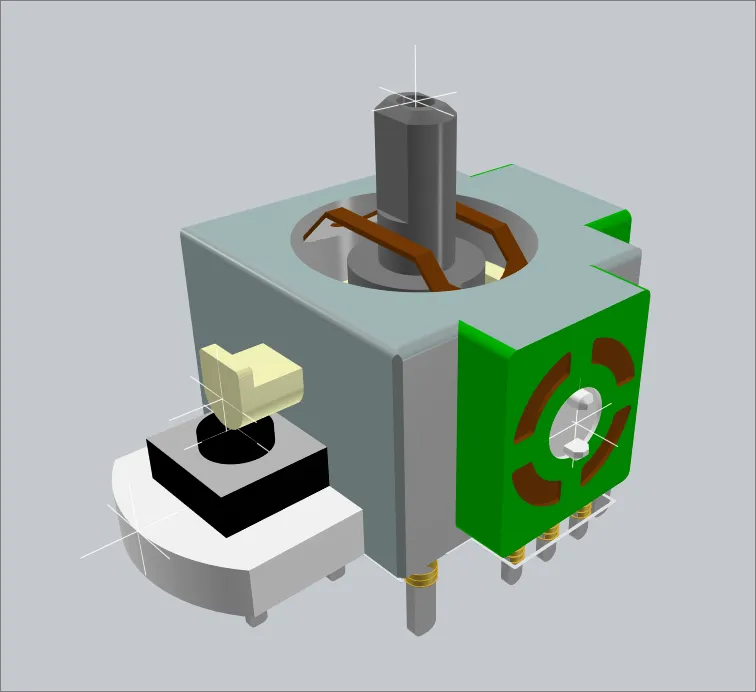
These snap points were added using the automatic snap to hole center capability.
Snapping to these locations is also available when using the
Reports » Measure Distances command in 3D Layout Mode.
Orienting a Model in the Properties Panel
An excellent approach to orienting a model is to use the 3D Body mode of the Properties panel. Because the values can be edited from the keyboard, it is easy to quickly test various X, Y or Z values and change the orientation as you observe the model in 3D. The keyboard can be used to:
-
Ctrl+F – to Flip the view over.
-
M – to move an object.
-
J – to Jump to a location in the design space.
-
R – to select Reference (the PCB library editor design space origin) from the Jump sub-menu.
-
Enter – to apply the value just typed into the panel and also to place the model being moved.
This can be used to rotate the model around each axis, and raise or lower it in the Z plane (demonstrated in the video below).
The Properties panel can be used to visually reorient the model.
Using the 3D Body Placement Commands
The software includes commands for orienting and positioning a 3D Body.
Orient and Position 3D Body
This feature requires you to select three anchor points that lie on the surface of the 3D model, then indicate the three reference points on the PCB to which each of these snap points should be mated. This technique does not necessarily require snap points to have been placed since any vertex on the 3D model can be used.
This feature will not work with extruded 3D models, since that model type has no 3-dimensional rotation support.
The process is the following:
-
Switch to 3D Layout Mode (shortcut: 3).
-
Choose the Tools » 3D Body Placement » Orient and Position 3D Body command from the main menus.
-
The Status bar will prompt you to select a model; click the generic model you want to reposition.
-
The cursor will change to the 3D positional cursor (blue, six-pointed), and you will be prompted to select points on the 3D model. Three anchors must now be selected, one after the other. Ideally, these will be an accurate reference, such as a pre-defined model reference point, or a snap point located at the center of a pin. The Status bar will indicate which anchor you are currently up to. Note that the Status bar displays a numerical reference value for the vertex or snap point that is currently under the cursor – user-define Snap Points have a low value, from 2 upward; keep an eye on this value to help identify the correct click location. Refer to the Defining Snap Points section to learn more about adding Snap Points.
-
Once the three anchors have been chosen, the next step is to select, in the same order, the three locations on the footprint where these anchors are to sit. Use the Status bar to guide you as you select the three locations. Note that the cursor will be blue as you move it through the design space, but will change to green if you are over the center of an object, such as a pad.
-
As soon as the third anchor location has been clicked on, the model will change its orientation and position as the software attempts to mate these three locations. The command will then terminate.
Resulting rotation values and standoff height will be reflected for the selected 3D Body, after the move, in the Properties panel. These can be adjusted to fine-tune placement as required.
This process is demonstrated in the video below.
Video demonstrating the process of re-orienting a Generic Model.
Position 3D Body
This feature uses two points to perform its function; one selected on the 3D model and then one corresponding point picked on the board/footprint. This technique does not necessarily require a snap point to have been placed since any vertex on the 3D model can be used.
Note that this command repositions the 3D Body using a lateral translation only. No rotations will be performed as only two points are used in the translation.
The process is the following:
-
Switch to 3D Layout Mode (shortcut: 3).
-
Choose the Tools » 3D Body Placement » Position 3D Body command from the main menus. The cursor will change to a cross-hair and you will be prompted to select the 3D model that you want to position.
-
Position the cursor over the 3D model of interest and click, or press Enter. The cursor will change to the 3D positional cursor (blue, six-pointed), and you will be prompted to select a point on the 3D model.
-
Move the 3D cursor over a vertex, or snap point, and click, or press Enter, to define the main anchor point. This is the 3D model anchor point, which will be used to intersect precisely with the board/footprint anchor point.
-
The cursor will now change to appear as two blue cones (selection mode), and you will be prompted to select a point on the board/footprint.
-
Position the cursor and click, or press Enter, to define the main anchor point's destination. This is the destination point for the 3D model's main anchor point when the body is repositioned.
-
After the destination point is chosen for the board/footprint, the 3D model will be repositioned accordingly.
Set Body Height
This feature is used to adjust the height of a chosen 3D Body relative to the top surface of the board/footprint.
The process is:
-
Switch to 3D Layout Mode (shortcut: 3).
-
Choose the Tools » 3D Body Placement » Set Body Height command from the main menus. The cursor will change to a cross-hair and you will be prompted to select the 3D model that you wish to position. All 3D model-types are supported.
-
Position the cursor over the 3D model of interest and click, or press Enter. The cursor will change to the 3D positional cursor (blue, six-pointed), and you will be prompted to select a point on the 3D model.
-
Move the 3D cursor over a vertex (or snap point) on the 3D model, and click, or press Enter, to define the point on the model whose height above the board/footprint is to be set.
-
The Choose Height Above Board Top Surface dialog appears. You will now specify where that point on the model is to be located in the Z-plane; either on the Board Surface, or at a Custom distance from the surface of the Board Side that the 3D model is currently placed on.
-
If a custom height is required, select Custom and enter the height required (positive or negative) for the nominated point on the 3D model in relation to the surface of the board/footprint.

The Choose Height Above Board Top Surface dialog
-
Click OK - the 3D model will be repositioned in the Z-plane accordingly.
When a point on a 3D model is prompted to be selected during use of the Orient and Position 3D Body, Position 3D Body, Set Body Height or Measure Distances command, press Tab to access the Choose Selectable Points dialog from where you can choose should vertices and/or snap points on the 3D model to be able to be selected and measured from.

The Choose Selectable Points dialog
Align Face With Board
This feature is used to position a chosen 3D Body so that its selected face is aligned with the surface of the board/footprint.
-
Only a flat (planar) surface can be used for alignment.
-
The surface of the board/footprint (top or bottom) that is referenced, is determined by the Board Side setting, in the Properties section of the Properties panel (when viewing the properties for the selected model).
The process is the following:
-
Switch to 3D Layout Mode (shortcut: 3).
-
Choose the Tools » 3D Body Placement » Align Face With Board command from the main menus. The cursor will change to a cross-hair and you will be prompted to select the 3D model that you wish to align.
-
Position the cursor over the 3D model that you wish to align and click, or press Enter. The model will become transparent.
-
Move the cursor over the 3D model to locate a face. Where a flat surface is found under the cursor, it will become opaque with a thin blue border.
-
Once the appropriate face has been found, click, or press Enter - the selected face will be aligned with the surface of the board/footprint.
Perform 3D Collision Checks within the PCB Editor
Perhaps the greatest strength of the 3D PCB editor is the ability to perform 3D collision testing. As well as catching general component-to-component collisions, you can also confidently position one component under another, or test if the loaded board fits correctly into the enclosure.
Collision testing relies on the Component Clearance design rule. Add Component Clearance design rules to check for collisions between components that include 3D body objects in the X, Y and Z planes. This allows you to check the clearance of one component over another component. Multiple rules can be defined to handle different clearance requirements. Note that the Design Rule Check does not test if a 3D body object is passing through the board.
This is a binary rule, meaning it tests between this object(s) and that object(s).
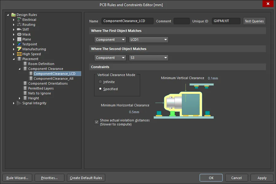
Multiple Component Clearance design rules can be defined, to precisely control the collision testing process.
The default behavior is to display the objects in violation, and the distance between those two objects. To see the exact location of the minimum separation between the objects, enable the Show actual violation distances option in the Component Clearance design rule.
Collisions are detected as you work. The rule being applied in this animation is shown in the previous image, it allows the push button body to fit under the LCD.
You can also import the product case, and 3D clearance checking can be performed (hover the cursor over the image below).
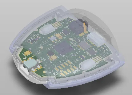
For a rigid-flex design, the board can be interactively folded, which is ideal for performing clearance checking of the board in its installed state.
The software can only perform collision testing between STEP models and a single board design; it cannot perform collision testing between multiple PCB designs. To test for collisions between two PCB designs,
create a Multi-board assembly.
Referencing a 3D Model in a Design Rule
To get the most out of the design rules system, it is important to understand how to best scope the design rule. The rule scope defines the set of objects targeted by that rule, for example, a rule scoped with the InPolygon keyword will apply to all of the primitives within all of the polygons on the board. To target the objects within a specific polygon, you would use the InNamedPolygon('PolygonNameHere') keyword.
If you are creating a rule to target a specific component, you can use the query keyword InComponent('ComponentDesignatorHere'). That rule scope will target all objects within the component C1, including the pads, overlay tracks, 3D model, and so on.
If you only want the rule to target the 3D model in a component, you can use the id keyword in the design rule. For example, in the video above, the LCD is a separate sub-assembly, with a designator of LCD1. The 3D model used in that component has an id value of LCD_2x16, as shown in the first image below. To use this id, the rule could have been configured as shown in the second image below.


The 3D Body Identifier can be used to scope a design rule so that it only targets the component's 3D model.
Extracting 3D Models from a PCB Library
Where 3D models (STEP, Parasolid® and SOLIDWORKS®) have been embedded into the 2D footprint models within a PCB Library document (*.PcbLib), the PCB footprint editor provides a utility with which to extract those models. To do so:
-
Open the PCB Library you want to extract 3D models from.
-
Choose the Tools » Extract 3D Models command from the main menus.
-
In the Generate 3D Model Files from PCB Libraries dialog that appears, specify where the generated files are to be stored – either in a sub-folder of the location in which the source PCB Library resides (the Specify the destination for output files option) or in a specified folder elsewhere (the In the specified dicrectory option). If the nominated folder exists, it will be used. If not, it will be created. Select (
 ) to specify the directory in which you want the output files to reside.
-
Optionally choose to Overwrite existing files – have existing 3D model files with the same name overwritten when new files are generated.
-
After defining options as required, click OK. Generation will proceed and a confirmation dialog will appear when the process is complete, stating how many 3D model files were generated.
Each 3D model file is named using the name of the 2D footprint model.
-
Only embedded 3D models can be extracted (not extruded, cylinder, or sphere).
-
3D models can be extracted only from a file-based PCB library (
*.PcbLib), not from a Workspace footprint.
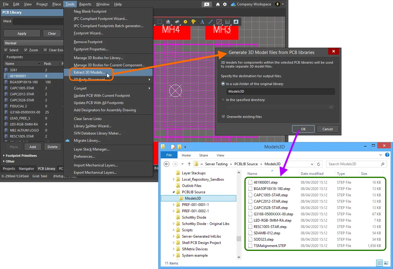
Example 3D model files generated from a PCB Library by using the extraction tool.
Uploading 3D Models to a Connected Workspace
Altium Designer, in conjunction with your connected Workspace, caters for the ability to create and manage Workspace 3D Models. Used similarly to file-based linked 3D models, a Workspace 3D Model can hold a 3D model file that is then referenced through a 3D body attached to a standard 2D footprint.
A new revision of a 3D Model Item can be created by uploading the applicable model file. This can be performed in a couple of ways - see Uploading Data into a New Revision of an Item for more information.
Supported formats for the uploaded model file are:
-
STEP File (
*.step; *.stp)
-
Parasolid File (
*.x_t; *.x_b)
-
SolidWorks Part File (
*.sldprt)
Note that when uploading more than one 3D model file by drag and drop operation from Windows Explorer to the Explorer panel, the Release Manager dialog opens.
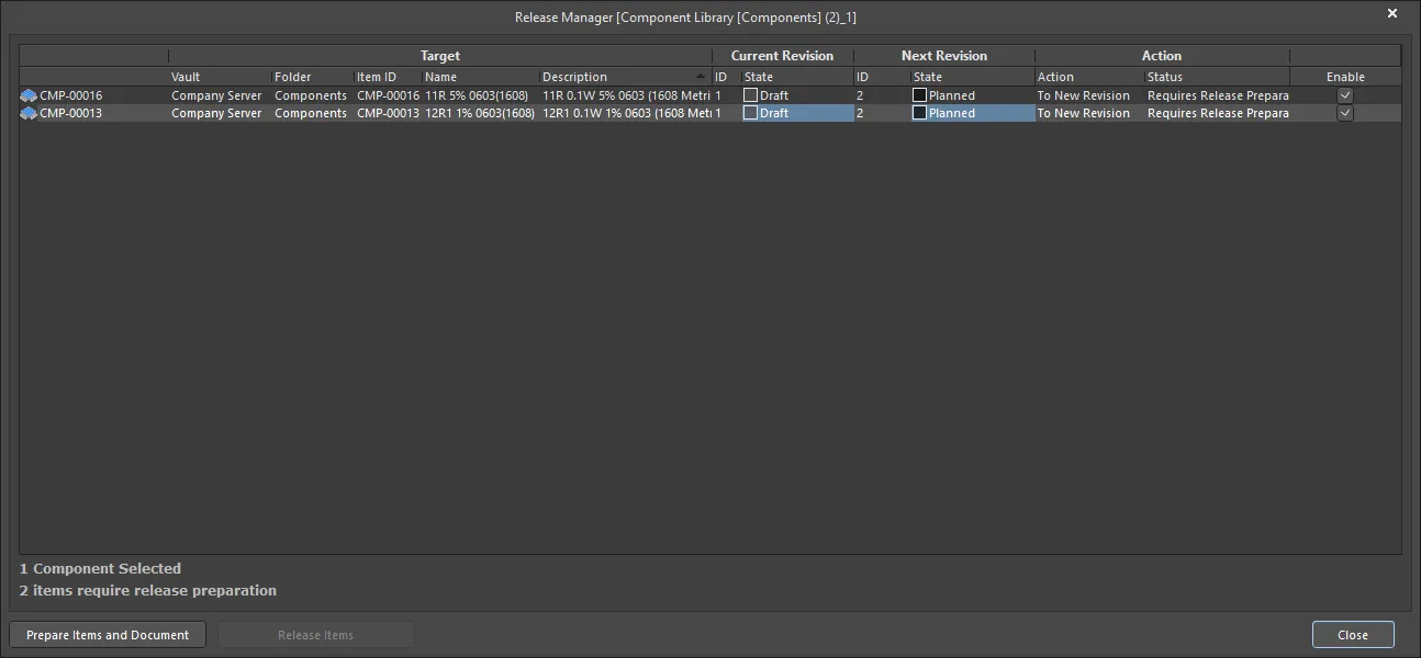
The Release Manager dialog
Options and Controls of the Release Manager Dialog
Grid Region
The grid presents all information relating to the link between an item and its vault-based Item, as well as the actions that will be taken if the source entity is included in the release process. The following information is displayed:
-
Component - the component to be released.
-
Target - provides information regarding the link to the Item that is either already established (if released already) or will be established (if awaiting initial release). It consists of the target Vault, the Folder within that vault, the Item ID, Name and Description of the Item itself.
-
Current Revision - if the item has been released previously, this region provides information about the latest released revision. It includes the revision ID and lifecycle State.
-
Next Revision - provides information about the next revision of the item that will be created to receive data from a subsequent release of the item. It includes the revision ID and lifecycle State of that revision which, for a new release, will always be in the
Planned state.
-
Action - shows the Action that will be taken by the Release Manager for this particular item as part of the release process. For an entity that has not yet been released, this entry will display
To New Revision. The associated Status field is used to indicate the next step to be taken in the process (e.g., Requires Release Preparation) and once the release process is complete reflects the result.
-
Enable - this checkbox controls whether the item is included as part of the release process (checked) or excluded from the process (unchecked).
-
xx Component(s) Selected - displays the number of items selected in the dialog.
-
xx Items require release preparation - displays the number of items that require release preparation prior to release.
-
Prepare Items and Document - click to prepare the documents and corresponding items for entities being released.
-
Release Items - after the items are prepared for release, the Release Items button becomes available, inviting you to proceed with the release. If you realize there are items that you would rather not release, uncheck the associated Enable checkbox at this time.
-
After preparing the documents, if you attempt to close the Release Manager before releasing, a warning dialog will appear. You are warned that the links to new target item revisions – written to the source library document as part of the preparation phase – will become invalid. It is strongly recommended that you proceed with the release at this stage.
-
The time taken to release the chosen 3D models will be shown in the Output panel.
Updating a 3D Workspace Model
If you need to change the 3D model stored in a Workspace 3D Model, upload the required new model to that Workspace 3D Model – the new model will be stored in the next revision of that Workspace 3D Model.
Updating Related Footprints
When you make a change to a 3D model, the moment you upload that change into a new revision of the Workspace 3D Model, any Workspace Footprints that use that model will become effectively out of date, still using the previous revision. In most cases, you will no doubt want to re-save those Workspace Footprints, with the respective model links updated to use the latest revision available. To streamline this process, your Workspace, in conjunction with Altium Designer, facilitates the ability to update related footprints – at the point of uploading to the latest revision of the 3D model.
Once uploaded, if any footprints currently reference the 3D model, a dialog will appear asking whether or not you wish to update those Workspace Footprints.
If you want to keep all related Workspace Footprints using the current revision of the 3D model, click No in the dialog. Only the model itself will then be uploaded.
A PCB footprint document is then opened in its associated temporary editor (for direct editing). When multiple footprints use the 3D model, rather than separate instances of PCB footprints being opened, a document containing all affected PCB 2D/3D component models is presented.
The revision of the referenced 3D model is not updated to the latest automatically – you will need to do this manually, if required, from the
Properties panel.
Once the 3D body for a model is updated to reference the latest revision of the Workspace 3D Model (where needed), select the Save to Server command from the main menus (shortcut: Ctrl+Alt+S) to save the modified model(s) into new revision(s) of the corresponding Workspace Footprint(s), back in the target Workspace.
As part of the re-saving of the Workspace Footprint(s), you will also have the opportunity to update any parent component(s) – this is performed automatically if the option to update is left enabled.
Browsing 3D Bodies Used in a PCB Design
In the PCB panel’s 3D Models mode, its three main regions change to reflect the 3D bodies hierarchy of the current PCB design (in order from the top):
-
Component Classes
-
Specific Components associated with the component class that have associated 3D body object(s) or free models (non-PCB mounted, free-floating 3D bodies)
-
The individual 3D bodies for each component or free Models
Double-click a component entry in the Components region of the panel (or right-click then choose Properties) to open the Component mode of the Properties panel where you can edit its properties in detail. Similarly, double-click a model entry in the Models region of the panel (or right-click then choose Properties) to open the 3D Body mode of the Properties panel in which you can edit the complete 3D body properties.
The PCB panel can be used to select display properties for 3D models. The  icons represent different levels of transparency from 100% (hidden) down to 0% (solid) in increments of 25%. You can select multiple components and apply the same display controls to them at once using the Highlighted Models options.
The  icon may be used to enable or disable Design Rule Checking of 3D object types that contain a STEP model. The icon may be clicked once to uncheck (or disable) the feature, or clicked twice to check (or enable) the feature.
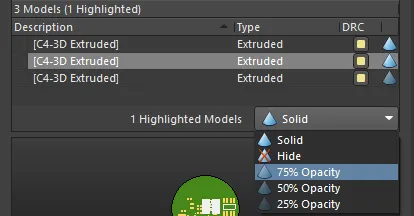
The selected model being set to 75% Opacity. Multiple models can also be selected and changed in one step.