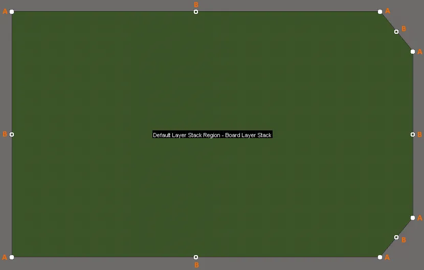
Aコマンドを起動すると、既存のボード形状が緑色に変わります。外側の形状は一連のエッジによって定義され、各エッジは白一色の正方形で示される端点と白空の正方形として示される中心頂点で表されます。各端点は、2 つのエッジが交わる位置を表します。

編集モードに入った後の基板形状例の編集ハンドル。
- Aをクリックしてドラッグし、現在のモードに応じて次のいずれかを実行します(モードを変更するにはShift+Spacebarを使用します)。
- Moving Vertex mode - 端点を端点として維持しながら、端点を自由に移動します。
- Miter to Segment mode - 移動する端点がそのエッジの中心点になる新しい直線エッジを作成します。
- Miter to Arc mode - 移動する端点がそのエッジの中心点になる新しい曲線エッジを作成します。
- Bをクリックしてドラッグし、現在のモードに応じて次のいずれかを実行します(モードを変更するにはShift+Spacebarを使用します)。
- Move mode - 端点を含むエッジ全体を自由に移動します。移動した中心点は、そのエッジの中心点のままです。
- Break mode - 中心の頂点を移動し、新しい終了点に変換し、元のエッジを 2 つに分割します。終点の頂点は元の位置に固定されたままです。
- Incurvate mode - エッジに曲率を追加し、端点を元の位置に固定します。移動した中心点は、そのエッジの中心点のままです。
- 編集ハンドルから離れたエッジ上の任意の場所をクリックし、ドラッグしてそのエッジをスライドします - 移動するエッジを縮小または拡大して、隣接するエッジの位置を維持します。
- 編集ハンドルから離れたエッジ上の任意の場所をCtrl+クリックして、新しい終了頂点を挿入します。
- 終了点(A)をクリックしたまま、Delete キーを押してその頂点を削除します。または、Ctrl キーを押しながら、削除する終点の頂点 (A) の上にマウスを置きます。白い十字が表示されます。クリックして押し続けると、頂点が削除されます。
編集モードを終了するには、設計領域内の任意の場所(ボード形状上または基板形状以外の場所)をクリックします。
- 頂点を移動すると、緑色の配置ガイドが表示されます。これらは、頂点の位置によって新しいエッジが既存のエッジと整列する場合や、円弧の弦が隣接するエッジと整列する場合など、便利な場所に表示されます。ガイドラインが表示されるとわずかに粘着性があり、その頂点位置を維持しやすくなります。頂点の移動中に必要な場合は、Shiftを押したままにすることでガイドラインを無効にすることができます。
- デフォルトのスナップグリッドは、ボード形状の外接する長方形で定義される領域を埋めるために拡張/縮小されます。
- ボードプランニングモード(Advanced Rigid-Flexモード - グラフィカル編集スペースの上部にあるアクティブバーには6つのボタンがあります):
- Place » Board Region - このコマンドを使用して、ボード領域をインタラクティブに定義します(単一領域の基板の場合、基板領域は基板形状を定義します)。ボードの配置領域の詳細を参照してください。
- 2D Layoutモード:
- Design » Board Shape » Define Board Shape from Selected Objects - 閉じた形状を定義する線分プリミティブや円弧プリミティブのセットを選択し、このコマンドを使用して、形状に一致するように基板形状を再定義します。
- Design » Board Shape » Create Primitives from Board Shape - 基板形状からの線分/円弧プリミティブダイアログで設定した設定に従って、基板形状の境界に沿ってプリミティブのセットを作成します。
- 3D Layoutモード:
- Design » Board Shape » Define Board Shape from 3D body - このコマンドを使用して、3D モデルの目的のサーフェスを選択して基板形状を定義します。
さらに、ボード計画モードで次のコマンドを使用できます。
-
Design » Move Board Shape - このコマンドを使用して、ボード図形を現在のドキュメント内の別の位置に移動します。このコマンドを使用すると、ボード形状のみが移動されます。実際の設計オブジェクトと構成オブジェクトは移動されません。
コマンドを起動すると、図形のアウトライン コピーがカーソルの左下隅にアタッチされます。図形をワークスペース内の目的の新しい場所に移動し、クリックするかEnterを押して配置を有効にします。移動中に、Spacebarを押して基板形状を反時計回りに回転させるか、Shift+Spacebarを押して時計回りに回転させるか(回転ステップサイズは、環境設定ダイアログのPCBエディタ – 一般ページで定義します)、またはXキーまたはYキーを押して、X軸またはY軸に沿って基板形状をそれぞれミラー化します。移動せずにキャンセルするには、右クリックするかEscを押します。
-
Design » Move Board - このコマンドを使用して、ボード全体 (ボードシェイプと、そのシェイプ内のすべてのデザインオブジェクト) を現在のドキュメント内の別の位置に移動します。
コマンドを起動すると、ボード形状のアウトラインコピーがカーソルにアタッチされ、カーソルの左下隅に保持されます。形状をデザイン領域内の目的の新しい位置に移動し、 をクリックするか、Enterを押して配置を有効にします。すべての構成設計オブジェクトも移動して、基板形状内の位置を維持します。移動せずにキャンセルするには、右クリックするかEscを押します。
選択したオブジェクトからボード形状を定義するコマンドと選択したオブジェクトからボード領域を作成するコマンドの違いは、最初のコマンドはコマンド実行時に作成される新しい領域で既存のボード領域をすべて置き換えるのに対し、2番目のコマンドは既存のボード領域を削除することなく、追加のボード領域を作成することです。
選択したオブジェクトからボード形状を定義する
ボード形状は、選択したオブジェクト(2Dレイアウトモードで)からも定義できます。通常、これはキープアウトレイヤーや機械レイヤーに配置された一連の線や円弧になります。
次の手順を使用します:
- 表示モードを2D Layoutモードに設定します。 (Viewメニュー).
- View Configurationパネルを開き、ダブルクリックして、基板形状を保持する Mechanical レイヤーを編集します。Edit Layer ダイアログが開き、下のビデオに示すように、レイヤーの種類を
Board Shapeに設定できます。
- シェイプを保持する Mechanical レイヤをアクティブレイヤにして、オブジェクトを選択します。Edit » Select » All on Layer上のすべて コマンドがこれに最適です。選択セットには、基板外形の形状を形成するトラックと円弧のみを含める必要があります。
- すべてのオブジェクトを選択したら、Design » Board Shape » Define Board Shape from Selected Objectsコマンドを実行します。ボード形状は、選択した線で定義されたパスをたどるように更新されます。選択したオブジェクトの中心線に追従できない場合は、警告ダイアログが表示されます。表示モードがボードプランニングモードに変わります。
標準リジッドフレックスモードを使用したボード形状のデモンストレーション
このビデオでは、選択したオブジェクトからボード形状を作成し、必要な3つの領域を作成するために分割線を配置する方法を示しています。
アドバンスドリジッドフレックスモードを使用したボード形状のデモンストレーション
このビデオでは、まず選択したオブジェクトからボード形状を作成し、次に必要な3つの領域を作成するために形状をスライスする方法を示しています。その後、選択したオブジェクトから3つのボード領域を定義する別のアプローチを示しています。これらのデモンストレーションは、このページの冒頭で説明されているように、リジッドフレックス2.0の機能を使用しています。
ソフトウェアは、選択されたオブジェクトの中心線に基づいて形状を見つけようとします。一つのトラック/円弧セグメントの端の座標が次のトラック/円弧セグメントの座標と正確に一致しない場合、境界識別アルゴリズムは失敗し、失敗した場所を示すメッセージが表示されます。代わりにトレースアルゴリズムを使用することを提案します。トレースアルゴリズムはトラック/円弧オブジェクトの外側のエッジに沿って進むため、ボードの形状は中心線から作成されたものとはわずかに異なります。この違いの影響を設計が受け入れることができる場合のみ、このオプションを選択してください。
ボード形状に使用するアウトラインのインポート
基板の形状は、DXF/DWGデータとしてインポートされた閉じたアウトラインから定義することができます。
DXF / DWGデータを機械層にインポートする機能と選択したオブジェクトから基板の形状を定義する機能を組み合わせることで、機械CADパッケージで定義された形状をPCBエディタに転送することができます。
新しい基板をインポートする準備をするには:
- File » New » PCBを選択します。新しい空のPCBが開きます。黒い領域は、現在のボード形状を表します。
- 新しい形状をインポートする前に、設計の要件とインポートする形状に合わせて、必要に応じて以下を設定します:
- 単位 - 必要に応じて、BoardモードのPropertiesパネルのOtherセクションで単位を設定します (画像)。
- グリッド - グローバル ボード スナップ グリッドをダブルクリックし、必要に応じてBoard モードのPropertiesパネルのGrid Managerセクションで設定します (画像)。
- 原点 - 新しいPCBの場合、ユーザー定義可能な原点のデフォルト位置は、設計領域の左下の絶対原点です。メインメニューからEdit » Origin » Setを選択し、クリックして、ユーザー定義可能な原点の位置 (現在の基板形状の左下隅など) を定義します。これは、入力アウトラインの原点の位置に合わせて設定するのに役立ちます。T
次の手順では、ボードの形状を .DXF または .DWGファイルからインポートします。インポートする形状は閉じた形状である必要があり、内部カットアウトは自動的には作成されません(ただし、インポートされたオブジェクトから後で定義できます)。
- File » Import » DXF/DWG を選択して Import Fileダイアログを開き、ダイアログの右下にあるファイル タイプが
AutoCAD ファイル(*.DXF、*.DWG)をクリックし、ブラウズして必要なファイルを見つけます。
- 開くボタンをクリックすると、Import from AutoCADダイアログが開きます(画像)。
- 必要に応じて、縮尺、デフォルトの線幅、レイヤーマッピングを設定し、OKをクリックします。
- 各DXF/DWGオブジェクトはオブジェクトにマッピングされ、設計空間に表示されます。
- 基板形状オブジェクトを保持する Mechanical レイヤをアクティブレイヤにして、そのレイヤ上のすべてのオブジェクトを選択します(Edit » Select » All on Layer)。
- 選択した外形と一致するように基板形状を更新するには、Design » Board Shape » Define from Selected Objectsコマンドを実行します。T
- 基板に基板の切り欠きが含まれている場合は、切り欠きのアウトラインを選択し、Tools » Convert » Create Board Cutout from Selected Primitiveコマンドを実行することで作成できます。
ソフトウェアは、選択されたオブジェクトの中心線に基づいて形状を見つけようとします。一つのトラック/円弧セグメントの端の座標が次のトラック/円弧セグメントの座標と正確に一致しない場合、境界識別アルゴリズムは失敗し、失敗した場所を示すメッセージが表示されます。代わりにトレースアルゴリズムを使用することを提案します。トレースアルゴリズムはトラック/円弧オブジェクトの外側のエッジに沿って進むため、ボードの形状は中心線から作成されたものとはわずかに異なります。この違いの影響を設計が受け入れることができる場合のみ、このオプションを選択してください。
3Dボディからボード形状を定義する
この機能は、インポートされた3Dモデルの表面(面)に基づいてボード形状を再定義します。サポートされるモデル形式には、STEP (*.Stpまたは*.STEP)、Parasolid (*.x_tまたは*x_b)、またはSOLIDWORKSパーツファイル(*.SldPrt)が含まれます。これを使用すると、複雑なボード形状を迅速に作成し、電子設計と機械設計領域間の統合を支援できます。これは2段階のプロセスです:最初にSTEPモデルがインポートされ、次にSTEPモデルから必要な形状が選択されます。
ボード形状を定義するためには、平面(平らな面)のみが使用できます。
これを行うには:
- View » 3D Layout Mode(ショートカット: 3) に切り替えます。
- 3Dモデルをインポートするには、3Dボディを配置します(Place » 3D Body)。
- Choose Modelダイアログで、モデル ファイルを見つけて選択します。3DモデルはPCBエディタにインポートされ、3D Bodyオブジェクト内に保存されます。このモデルは、必要に応じて基板形状を再定義した後、PCBから削除できます。
- Design » Board Shape » Define Board Shape from 3D bodyを選択します。
- ステータスバーに、
Pick a 3D bodyと表示されます。インポートした 3D ボディをクリックして選択します。モデルが透明になります。
- カーソルが十字線に変わり、ステータスバーに
Choose Faceを求めるプロンプトが表示されます。各面にカーソルを合わせると、輪郭が表示されます。カーソルの下に平らな表面がある場合、その表面は不透明になり、細い青い境界線が表示されます。正しい面をクリックして選択します。
- Board Outline Creation Successfulダイアログが表示され、選択した表面(通常は最上層)にどのPCB表面を位置合わせするか、および3Dモデルをビューおよびデザインルールチェックから非表示にするかどうかのオプションが表示されます。非表示と無効化の動作は、必要に応じて、PCBパネルの3Dモデルモードで後で変更できます。

STEPモデルをPCBファイルに埋め込んだままにしておくか、リンクした状態にしておくと、STEPファイルが変更された場合に通知されます。また、形状がまだ開発中で更新が予想される場合には、形状を更新するように促されるため、便利です。
X-Y平面に合わせて配置された面のみがボード形状の作成に使用できます。X-Y平面に合わせる必要があるモデルの面を選択した場合、続行する前にその面を合わせるように求められる
![]() 確認ダイアログ
確認ダイアログが表示されます。このダイアログでは、選択した面を基準にしてモデルをボードの上面または下面に対して配置することもできます。これは、モデルの垂直位置も同時に設定できることを意味します。合わせた後、
設計 » ボード形状 » 3Dボディから定義を再度選択する必要があります。ボード形状が再定義された後、3Dボディを非表示にするオプションが提供されます。
ボード形状からプリミティブを作成する
選択したプリミティブからボード形状を定義するだけでなく、設計 » ボード形状 » ボード形状からプリミティブを作成 コマンドを使用して、ボード形状からプリミティブを作成することも可能です。このコマンドを実行すると、Line/Arc Primitives from Boardダイアログが開きます。

ボード形状からの線/円弧プリミティブダイアログ
collapse collapsed class="" title="ボード形状ダイアログからの線/円弧プリミティブのオプションとコントロール "]
- Width - 生成される線/円弧プリミティブの幅を指定します。
- Layer - 生成された線/円弧プリミティブのドロップダウンリストからレイヤーを選択します。
- Include Cutouts - アウトラインプリミティブの生成時にカットアウトを含めることができるようにしました。
- Include layer stack regions - アウトラインプリミティブの生成時にレイヤースタック領域を含めることができるようにします。レイヤースタック領域は、一意のレイヤースタックを割り当てることができるPCBのユーザー定義領域です。ボードは複数の領域に分割でき、各領域には個別のレイヤースタック配置が割り当てられます。レイヤースタックアップ(レイヤースタックマネージで定義)は、基板のリジッド領域とフレキシブル領域の両方に対応するように構成できるため、リジッドフレックスPCB設計が容易になります。レイヤースタックアップ(レイヤースタックマネージャーで定義)は、基板のリジッド領域とフレキシブル領域の両方に対応するように構成できるため、リジットフレックスPCB設計が容易になります。レイヤースタック領域は、レイヤースタック領域モードで設定されたPCBパネルから参照できます。
- Route Tool Outline - 既定の動作では、アウトライン プリミティブの中心線がボード シェイプのエッジ上になるように配置されます。このオプションを有効にすると、ルート(ルーティング)ツールの外形の必要に応じて、線分/円弧オブジェクトが基板形状のエッジとカットアウトのエッジに接するように配置されます。
- Delete Existing Non-Net Lines/Arcs On Layer - 選択したレイヤー上の特定のネットに関連付けられていない既存の線/円弧を削除できます。