PCBの配線を行う際、アドレスバスやデータバスなど、複数の信号グループを同じ経路に沿って配線する必要があることはよくあります。これらの信号を個別に配線することもできますが、より迅速な方法はまとめて配線することです。メインのRouteメニューまたはActive BarからアクセスできるInteractive Multi-Routingコマンドを使用すると、複数のネットを同時に配線できます。
コマンドを選択する前に、配線に含めたい各ネットのソースパッドを選択してください。個別のパッドを選択するにはShift+click、複数の子パッドをまとめて選択するにはCtrl+click and dragで選択範囲を描画します。
コマンドを起動した後、マルチ配線を開始するためにクリックするよう指示されます。設計空間内で最初のトラックセグメントを配置したい位置をクリックし、その後、目的地に向かって必要に応じて配線を続けてください。バス間隔を現在のグリッドの増減単位で調整するにはB(Shift+B)ショートカットを使用します。バス間隔を適用可能な配線ルールで許可されている最小値に収束させるにはCを押します。その他の操作はインタラクティブ配線と同じショートカットで行えます:コンフリクト解決モードの切り替え、配線層の切り替えなど。
また、トラックのグループを選択してその端をドラッグする(Smart Dragとも呼ばれる)ことで、この配線モードに自動的に入ることも可能です。このモードでは、連続してドラッグすることで新しいセグメントを追加できます。
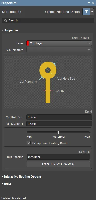
インタラクティブマルチ配線中にTabを押すと、PropertiesパネルがMulti-Routingモードで開きます。以下の折りたたみセクションには、利用可能なオプションやコントロールに関する情報が含まれています:
Properties

-
Layer – ドロップダウンから配線を行う層を指定します。
-
Via Template – ビアがテンプレートに関連付けられている場合、ここにテンプレート名が表示されます。
-
Via Hole Size – ビアの穴サイズを指定するか、配線中に4ショートカットキーを使用します。
-
Via Diameter – ビアの穴径を指定します。
-
Width – スライダーバーを使って幅を指定します。左端(Min)は、現在のネットに定義された設計ルールの最小幅を使用することを意味します。Preferredは、現在のネットに定義された設計ルールの推奨幅を使用することを意味します。右端(Max)は、現在のネットに定義された設計ルールの最大幅を使用することを意味します。
-
Pickup From Existing Routes – 配線を既存のトラックから開始する場合、既存のトラック幅を使用するには有効にします。つまり、現在の配線幅が既存トラックと異なっていても、配線を継続する際は既存トラックの幅が採用されます。
-
Bus Spacing – 希望するバス間隔を入力するか、Shift+Bショートカットを使用します。
-
From Rule – 既存の設計ルールに基づいてバス間隔を割り当てるにはクリックします。
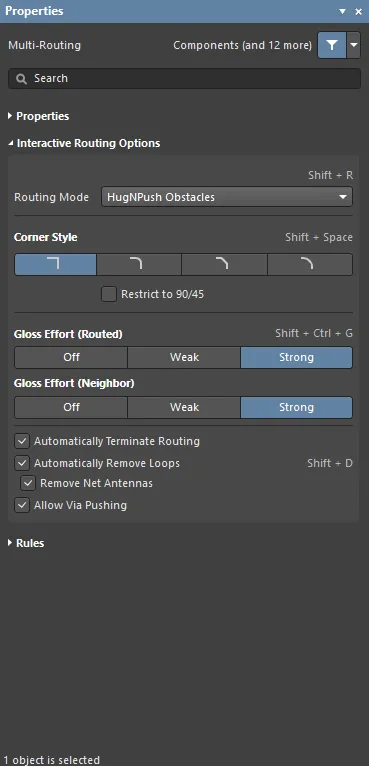
Interactive Routing Options

-
Routing Mode – ドロップダウンまたはShift+Rショートカットで希望する配線モードを切り替えます。選択可能なオプションは以下の通りです:
-
Ignore Obstacles – 既存オブジェクトを無視して配線を自由に配置します。違反箇所はハイライトされます。
-
Walkaround Obstacles – インタラクティブルーターが既存のトラック、パッド、ビアを回避して配線します。このモードで障害物を回避できない場合、ルートがブロックされたことを示すインジケーターが表示されます。
-
Push Obstacles – インタラクティブルーターが既存のトラックを押しのけて配線します。このモードでは新しい配線のためにビアも移動できます。障害物を押しのけられない場合、ルートがブロックされたことを示すインジケーターが表示されます。
-
HugNPush Obstacles – インタラクティブルーターが既存のトラック、パッド、ビアにできるだけ密着して配線し、必要に応じて障害物を押して配線を続けます。このモードで密着または押しのけができない場合、ルートがブロックされたことを示すインジケーターが表示されます。
-
Stop At First Obstacle – このモードでは、配線エンジンは最初に遭遇した障害物で停止します。
-
AutoRoute Current Layer – 現在の層のみで自動配線を有効にします。
-
AutoRoute MultiLayer – 複数層で自動配線を有効にします。
-
Corner Style – 希望する配線コーナースタイルを選択するか、Shift+Spacebarショートカットでコーナースタイルを切り替えます。
-
Restrict to 90/45 – 配線を90度および45度のみに制限するには有効にします。
-
Gloss Effort (Routed) – 希望するグロスレベルをパネルから直接選択するか、Shift+Ctrl+Gショートカットで以下の選択肢を切り替えます:
-
Off – このモードではグロス処理は基本的に無効です。ただし、配線やドラッグ後に重複トラックの除去などのクリーンアップは実行されます。このモードは、基板レイアウトの最終調整段階(例:トラックの手動ドラッグやパッドエントリのクリーンアップなど)で有用です。
-
Weak – このモードでは、インタラクティブルーターが現在配線中のトラック(またはドラッグ中のトラック/ビア)に直接接続されている、またはその周辺のトラックのみを考慮して低レベルのグロス処理を行います。クリティカルトレースやトラックレイアウトの微調整に有用です。
-
Strong – このモードでは、インタラクティブルーターが最短経路を探したり、トラックを滑らかにしたりするなど、高レベルのグロス処理を行います。基板レイアウトの初期段階で、迅速に多くの配線を行いたい場合に有用です。
-
Gloss Effort (Neighbor) – 現在配線中のネットによって押されるトレースに適用するグロスレベルを、パネルから直接以下の選択肢で選択します:
-
Off – このモードではグロス処理は基本的に無効です。ただし、配線やドラッグ後に重複トラックの除去などのクリーンアップは実行されます。このモードは、基板レイアウトの最終調整段階(例:トラックの手動ドラッグやパッドエントリのクリーンアップなど)で有用です。
-
Weak – このモードでは、インタラクティブルーターが現在配線中のトラック(またはドラッグ中のトラック/ビア)に直接接続されている、またはその周辺のトラックのみを考慮して低レベルのグロス処理を行います。クリティカルトレースやトラックレイアウトの微調整に有用です。
-
Strong – このモードでは、インタラクティブルーターが最短経路を探したり、トラックを滑らかにしたりするなど、高レベルのグロス処理を行います。基板レイアウトの初期段階で、迅速に多くの配線を行いたい場合に有用です。
-
Automatically Terminate Routing – 有効にすると、ターゲットパッドへの配線が完了した際、配線ツールはターゲットパッドfromで配線モードを継続せず、リセットされて次のソースパッドからの配線待機状態になります。このオプションを無効にすると、ターゲットパッドへの配線後も配線モードが継続し、前回のターゲットパッドが次の配線のソースとして使用されます。
-
Automatically Remove Loops– 手動配線中に作成された不要なループを自動的に削除できるようにします。これにより、冗長なトラックを手動で削除することなく、接続を再配線できます。ただし、電源ネットなどのループが必要なネットを配線する場合もあります。その場合は、Shift+D ショートカットを使用して、同じネットに対するこのグローバル設定を一時的に無効化できます。
-
Remove Net Antennas – このオプションを有効にすると、他のプリミティブに接続されていないトラックやアークの端部(アンテナ)を削除します。
-
Allow Via Pushing – Push Obstacles または HugNPush Obstacles モード時に、ビアの押し出しを許可する場合はこのオプションをチェックしてください。
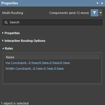
Rules

該当するデザインルールで定義された制約は、Rules セクションの Properties パネルに一覧表示されます。
-
Via Constaint – クリックすると、Edit PCB Rule ダイアログが開き、ルールの表示・編集ができます。
-
Width Constraint – クリックすると、Edit PCB Rule ダイアログが開き、ルールの表示・編集ができます。