Many of the outputs that you generate will require additional details. For example, the manufacturing drawing will need dimensions, the assembly drawing might need an enlarged view of a specific area of the board, and the fabrication drawing will need a Layer Stack Table and a Drill Table. These types of detail can be added in the PCB editor or in the PCBLIB Editor via footprint.
Note that while a PCB design can be documented right in the PCB editor, the software also includes an advanced, yet flexible graphical editing environment for creating board design production documents, called Draftsman. Complete with a dedicated set of drawing tools, the Draftsman drawing system provides an interactive approach to bringing together fabrication and assembly drawings with custom templates, annotations, dimensions, callouts, and notes.
► Learn more about Draftsman
General Purpose Drawing Layers
In the PCB editor, detail such as dimensions, and fabrication and assembly instructions are added on mechanical layers. The software supports an unlimited amount of general purpose mechanical layers, which are enabled in the View Configuration panel. These layers can be named as required (right-click on the name then select Edit Layer), and included in printouts and layer-based fabrication outputs.
Layer Stack Table
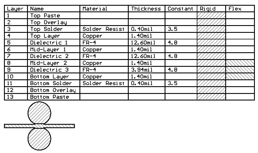
A Layer Stack Table can be placed on a PCB document alongside the design itself. It provides a detailed summary of the board layer stackups and how the layer groups are assigned.
A Layer Stack Table is a tabular graphic object that documents the layers, materials, thicknesses, and dielectric constants implemented in the current PCB design. It is placed and positioned alongside the board design in the design space and also includes a graphical key and option map that shows the layer stack used in each region of the board. A Layer Stack Table is an important documentation asset for designs with a complex layer stack structure, such as a rigid-flex design.
The Layer Stack Table is available in the PCB editor when the design space view is set to normal 2D mode (shortcut 2). After launching the Layer Stack Table placement command, the cursor will change to a cross-hair and you will enter Layer Stack Table placement mode. Placement is made by performing the following sequence of actions:
- Click to place the table.
- The editor remains in Layer Stack Table placement mode, ready to place another table if required. If not, right-click or press Esc to exit placement mode.
Note the Board Map that appears below the table. This is an outline of the board showing how the various layer stacks are assigned to regions of the board. The Board Map can be disabled or scaled by using the
Show Board Map option in the
Layer Stack Table mode of the
Properties panel.
Additional actions that can be performed during placement while the layer stack table is still floating on the cursor and before the center point of the layer stack table is anchored are:
- Press the Alt key to constrain the direction of movement to the horizontal or vertical axis, depending on the initial direction of movement.
- Press the Spacebar to rotate the layer stack table counterclockwise or Shift+Spacebar for clockwise rotation. Rotation is in increments of 90°.
To move a Layer Stack Table, click, hold and drag the table to the desired location.

Select and drag to reposition a Layer Stack Table.
Layer Stack Table Properties

The Layer Stack Table mode of the Properties panel.
Location
The

icon to the right of this region must be displayed as

(unlocked) in order to access the below fields. Toggle the lock/unlock icon to change its lock status.
- (X/Y)
- X (first field) - the current X (horizontal) coordinate of the reference point of the object, relative to the current design space origin. Edit to change the X position of the object. The value can be entered in either metric or imperial, include the units when entering a value whose units are not the current default.
- Y (second field) - The current Y (vertical) coordinate of the reference point of the object, relative to the current origin. Edit to change the Y position of the object. The value can be entered in either metric or imperial, include the units when entering a value whose units are not the current default.
- Rotation - the object's angle of rotation (in degrees), measured counterclockwise from zero (the 3 o'clock horizontal). Edit to change the rotation of the object. Minimum angular resolution is 0.001°.
Properties
- Layer - the layer to which the table is currently assigned. Use the drop-down to select a different layer.
- Alignment - use the drop-down to select the desired alignment.
- Units - use the drop-down to select either Metric (mm) or Imperial (mil).
- Show Board Map - enable to display an outline of the board showing how the various layer stacks are assigned to regions of the board. Use the slider bar to change the scale of the visualized board outline.
- Show Total Board Thickness - enable to display the thickness of the total board under the grid in the layer stack table.
- Line Width - specify the line width of the text within table. Line Width affects the line thickness of the text.
- Text Height - the current height of the text characters. Specify the text height within the table. Text Height also affects the table size. If the text height is set larger, the table will be expanded automatically.
Font Type
- TrueType - use this field to choose the required TrueType font. The Font drop-down list is populated with TrueType and OpenType (a superset of TrueType) fonts found in the \Windows\Fonts folder. Note that the list will include only entries for detected (and uniquely named) root fonts. Use the B (bold) and I (Italic) options to add emphasis to the text.
- Stroke
- Font - use this field to choose the required Stroke font. Available options are:
- Default - a simple vector font that supports pen plotting and vector photo-plotting.
- Serif - a more complex font that will slow down vector output generation, such as Gerber.
- Sans Serif- a more complex font that will slow down vector output generation, such as Gerber.
Stroke-based fonts are built into the software and cannot be changed. All three fonts have the full IBM extended ASCII character set that supports English and other European languages.
Columns
Use this region to specify which columns you want displayed in the layer stack table, the alignment of the text in that column, and the overall column width.
- Caption - the title of the column to be displayed.
- Align - click the alignment cell for the caption you want to align. You can continue clicking to cycle through the alignment options (i.e left, center, and right). Each click of the alignment field will change the alignment of the text for that column in the table.
- Width - click in the field to edit the width of the selected caption. When Auto is specified, the system automatically adjusts the column width according to the entered text in that column. You can enter the required width if desired.
- Add - use the drop-down to add a column in the layer stack table from the available options. In the drop-down, click the desired caption you want to appear in the table.
- Up - click to move the selected caption to move it one column to the left in the table. Use the Up button repeatedly to move the selected column additional columns to the left.
- Down - click to move the selected caption to move it one column to the right in the table. Use the Down button repeatedly to move the selected column additional columns to the right.
-
 - click to delete the selected caption from the table. A confirmation appears in the table asking if you want to delete the selected item. Click Yes if you do want to delete it; No if you do not.
Drill Table
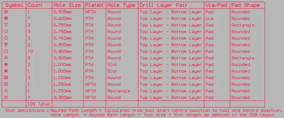
The Drill Table presents a live summary of all drill holes present in the board
A drill table is a standard element required for the manufacture of a Printed Circuit Board. The drill table lists the size and number of holes for each drill used on the board. Each drill size can be represented by a symbol, a letter, or the actual hole size. When a drill drawing is generated for the board, each actual drill site is marked by a symbol. The drill table updates in real-time as hole-containing objects, such as pads and vias, are placed or removed from the PCB design.
A Drill Symbol is displayed at each drill site on the Drill Drawing layer when the Show Drill Symbols option is enabled in the Drill Symbols dialog.
A Drill Table can be placed only in the PCB Editor. After launching the command, a drill table will appear attached to the cursor. Position the table in a suitable location outside the board then click or press Enter to place it.
Note that the drill table must be placed on the Drill Drawing layer. It will be automatically placed on the Drill Drawing layer even if this is not the currently active layer.
Additional actions that can be performed during placement while the drill table is still floating on the cursor and before the drill table is anchored are:
- Press the Tab key to pause the placement and access the Drill Table mode of the Properties panel, from where its properties can be changed on the fly. Click the pause button overlay (
 ) to resume placement.
- Press the Alt key to constrain the direction of movement to the horizontal or vertical axis depending on the initial direction of movement.
Moving a Drill Table
Click and hold anywhere within the drill table then move it to the desired location in the PCB editor design space.
Interactively Resizing a Drill Table
The drill table is automatically sized based on the specified Text Height setting, as well as the number of different hole sizes (rows) and the number of defined columns. To interactively resize the table, click once to select it then click and hold on a corner vertex then move to resize as required. Note that interactively resizing the table will also increase/decrease the font size.
Interactively Switching the Layer Pair to Preview
When the board includes layer-pairs, the displayed layer-pair is controlled by the Layers Pairs option in the Drill Table mode of the Properties panel.
This chosen layer-pair also can be switched using the:
-
PCB Editor right-click menu - right-click on the Drill Table then select the required layer-pair in the Drill Table sub-menu as shown in the image below.
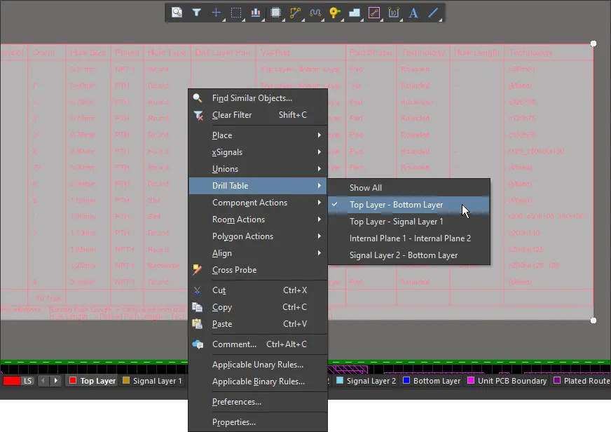
Right-click on the Drill Table to switch it to display another layer-pair
-
Layer-pair selection menu accessed via the Layer Tab at the bottom of the design space as shown in the image below.

Drill Table Properties

The Drill Table mode of the Properties panel.
Location
The

icon to the right of this region must be displayed as

(unlocked) in order to access the below fields. Toggle the lock/unlock icon to change its lock status.
- (X/Y) – the current X and Y locations of the Drill Table reference point. The reference point is the bottom left corner if Alignment = Bottom, or top left corner if Alignment = Top.
- Rotation – angle in degrees that the Drill Table is rotated.
Properties
Font Type
- TrueType – select to use fonts available on your PC (in the \Windows\Fonts folder). TrueType fonts offer full Unicode support. By default, the software links to a used TrueType font (they are not stored in the PCB file), which means the same font must be present on each PC that the design is moved to. Alternatively, embed used TrueType fonts in the PCB file using the options in the PCB Editor – True Type Fonts page of the Preferences dialog, where you can also select a Substitution Font to be used if a non-embedded Font is not available.
- Font – use the drop-down to select the desired TrueType font. Use the B to bold or I to italicize text.
- Stroke
- Font – use the drop-down to select the desired Stroke font. Choices are:
Default – a simple vector font designed for pen plotting and vector photo plotting.Sans SerifSerif
- Stroke Width – displays the width of the stroke.
- Show Footer – toggle to enable/disable displaying the footer of the table.
- Alignment – the table can be built from the bottom-up (Bottom), or from the top-down (Top). Use this setting to allow for table size changes without impacting surrounding objects in the design space.
- Table Border Width – width of the lines used to create the table border.
- Drill Symbols – click to open the Drill Symbols dialog in which you can assign symbols/letters to hole sizes.
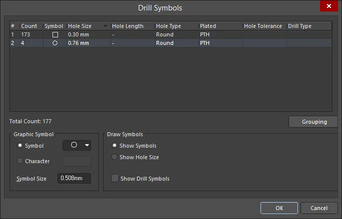
Options and Controls of the Drill Symbols Dialog
Grid Area
The grid area displays detailed information about the mapping of a symbol to a hole size. It can be customized by clicking on and dragging a column header to change the order of columns and right-clicking on a column header and enabling/disabling the checkbox to show/hide the column.
To sort the drill symbols, click once on a column heading to sort by that column. A small triangle will appear indicating the current sort direction. Click a second time to reverse the sort direction.
Grouping
Click the Grouping button to set which properties are to be used to control the assignment of symbol-to-drill events (holes). Holes are clustered initially by hole size and then assigned separate symbols whenever a grouping option that uniquely identifies them is enabled. For example, the design could include a round pad with a 1mm hole and another square pad with a 1mm hole. If Pad Shape is not enabled in Grouping, they will be assigned the same symbol. But if Pad Shape is enabled in Grouping, they will be assigned separate symbols.
Graphic Symbol
Each hole site can be represented by a symbol, a letter or a string showing the actual hole size. These options control the symbol style and size:
Draw Symbols
These options control the style of drill symbol and when they should be shown:
- Show Symbols - show a symbol at each hole site.
- Show Hole Size - show the actual drill size at each hole site as a numerical value.
- Show Drill Symbols - the default behavior is to not show drill symbols on the Drill Drawing layer. Enable this option to display the drill symbols.
-
 – click to refresh the table whenever there are design changes that affect the drill table. Note that the table is automatically updated during output generation.
Units
- Primary Units – use the drop-down to set the primary units to either Metric (mm) or Imperial (mil).
- Dual Units – use the drop-down to set the dual units to either Metric (mm) or Imperial (mil). Use
 or
or  to determine whether these units are displayed or hidden (respectively) in the design space.
Precision
- Primary Precision – use the drop-down to set the required precision (number of digits after the decimal point).
- Dual Precision – use the drop-down to set the dual precision (number of digits after the decimal point).
Columns
- Grid – displays all column headings (Caption) in the drill table, the Align setting, which repositions contents within the grid, the Width, and the Order in which the information in each column is displayed. To change from ascending to descending order and vice versa, click in the Order column to access a drop-down menu then select the desired order: Asc – ascending or Dsc – descending.
- Edit Columns – click to open the Columns dialog, with which to add new columns to the drill table or edit existing columns.
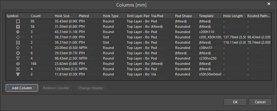
The dialog presents all existing columns, along with associated (read-only) data. Use the following buttons beneath the grid to curate the data to be presented in the table:
- Add Column - use to add a new colum to the drill table. Click to open a menu of available columns. Columns that are already used or not available are grayed-out in the menu. This command also is available on the right-click menu.
- Remove Column - click to remove the selected column(s). Note that there is no confirmation dialog; when the button is clicked, the column is deleted. This command also is available on the right-click menu.
- Change Header - click to open the
![]() Change column header dialog in which you can change the title of the selected column. This command (titled Change column header) also is available on the right-click menu.
Change column header dialog in which you can change the title of the selected column. This command (titled Change column header) also is available on the right-click menu.
The following additional commands are available from the right-click context menu:
- Text Alignment - use to align the text in the selected column. Choices include: Left, Center, and Right.
- Set column width - use to set the width of the selected column. Choices include: Autosize (default), and Manual. Clicking Manual opens the
![]() Set Column Width dialog in which you can enter the desired width.
Set Column Width dialog in which you can enter the desired width.
Design View
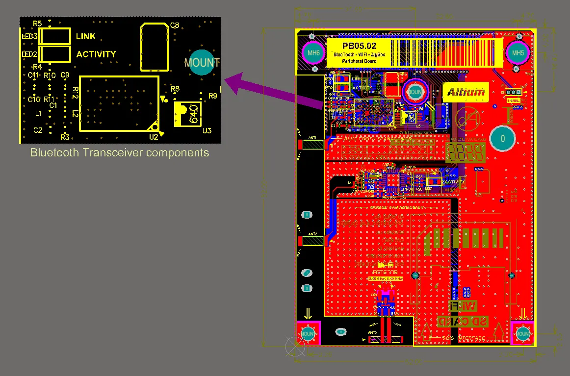
Place a Design View to show a specific area of the board. This example has been scaled to 200%.
The PCB Design View object is a graphic snapshot of any rectangular-shaped region of the current board or another board. It can be placed anywhere in the design space and scaled to any size.
A Design View can be placed only in the PCB Editor. After launching the Design View placement command, a design view will appear attached to the cursor. Position the design view in a suitable location then click or press Enter to place it.
Additional actions that can be performed during placement while the design view is still floating on the cursor and before the design view is anchored are:
- Press the Alt key to constrain the direction of movement to the horizontal or vertical axis, depending on the initial direction of movement.
After placement of the design view, you can define the display of desired layers by performing the following steps:
- With the Design View selected in the design space, open the Properties panel by double-clicking or right-clicking then choosing Properties from the context menu.
- Use the Define button in the Properties panel to interactively define the area of interest.
- In the Layers section of the Properties panel, click (toggle) the
 icon to enable the display of the desired layers. When enabled in the Properties panel, the desired layer(s) will display the
  icon.
icon.
Design Views are included in printed and PDF output. The Design View retains its own layer visibility settings in the output allowing it to present as required in the printed/PDF output. Note that the primitives on layers used in the Design View continue to obey the display settings defined for that layer in the Print dialog. For example, if the Top Overlay is displayed in the Design View and the Top Overlay is configured to display tracks in Draft mode for that output in the Output Job, then the Top Overlay tracks in the Design View will also present in Draft mode.
Note that Design Views are not included in Gerber or ODB++ output.
Once a Design View has been placed in the design space, you can interactively adjust the position, scale, size and focus of the View.
- Change the position – Click+Drag the Design View object to a new location on the PCB design space.
- Adjusting the Scale – click once to select the Design View then Click+Drag on a corner handle to scale the Design View up (drag out) or down (drag in).
- Adjusting the View Size – click once to select the Design View then Ctrl+Click+Drag on a corner handle to resize the Design View.
- Changing the Focus – Ctrl+Click+Drag anywhere within the Design View to slide the currently viewed area around within the Design View window.
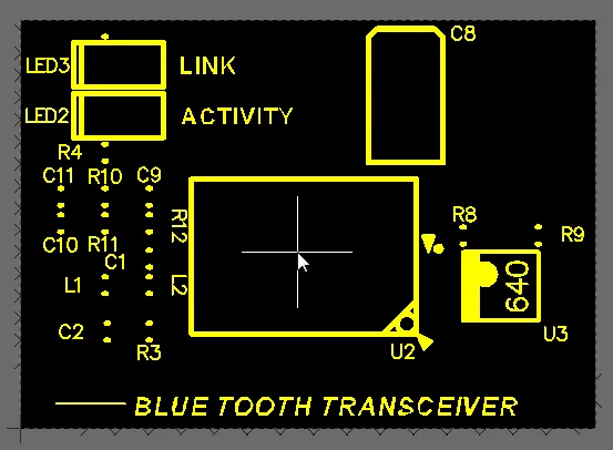
Ctrl+Click+Drag to slide and adjust the area currently being viewed in the Design View.
Design View Properties

The Design View mode of the Properties panel.
Location
The

icon to the right of this region must be displayed as

(unlocked) in order to access the below fields. Toggle the lock/unlock icon to change its lock status.
- (X/Y) - the current X and Y locations of the Design View reference point.
Properties
- This document - select to specify the properties for the currently active document.
- Specify document - select to specify the properties for a different document. When selected, click
 in the Document field then browse for the desired document.
- Document - click
 to search for and select the desired document when Specify document is selected.
- Mirrored - click to enable a flipped (mirrored) image of the board area in the Design View.
- Scale - click to define the object size as a multiplying factor.
- Title - enter the title of the Design View.
- Text Height - enter the Design View's title text height.
- Font - use the drop-down to select the desired font for the title. Use the color box to open a color chooser for the title text. Note that the color must contrast the design space background color for visibility.
- Define - click to return to the design space with a cross-hair cursor then use click-drag to define the rectangular region of the view.
Layers
This region provides a list of all board layers that can be configured to show specific layers in the Design View.
- Name - the name of the layer. Use the
 or
or  icon to show or hide (respectively) the listed layer in the Design View.
- Type - the layer type.
OLE Object
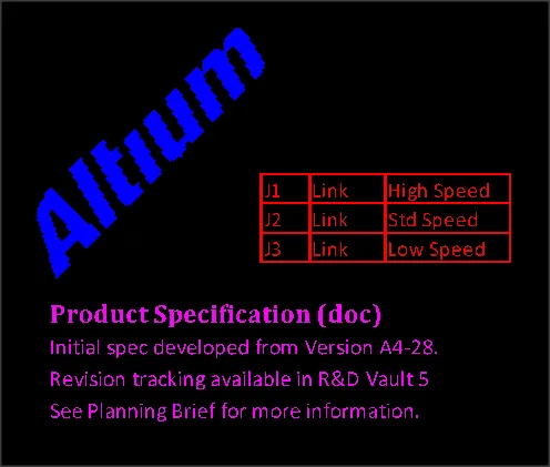
A placed sequence of OLE objects – an image, spreadsheet cells and word document text (top to bottom)
Object Linking and Embedding (OLE) technology in the PCB editor allows data supplied by Windows OLE applications to be embedded in a PCB design while actively linking back to the source application. In many cases, this allows the embedded PCB data to be edited from within the application that created it.
Typical OLE objects that might be placed in a PCB document include common Excel documents, Word documents, or graphics objects from a suitable OLE image application. The supported file types include universal formats such as CSV and XLS format spreadsheets, DOC and RTF word documents, and BMP image files.
OLE objects are available for placement/embedding in the PCB Editor. After launching the command, choose the desired file from the Choose File dialog then click to place the object in the design space.
Altium’s Smart Paste capability also allows a selection in an OLE application to be copied and pasted (Edit » Paste) into the PCB document as an OLE object. The text paste option (Edit » Paste Text) can be used to strip the text elements from an OLE object if required. These will be placed as PCB text objects.
Once placed, embedded objects can be proportionally scaled by clicking, holding and dragging their selection handles. With text-based objects such as Word and Excel documents, the embedded text is automatically scaled in size and thickness to suit the new dimensions.
- An OLE Object also can be converted to a collection of free primitive objects using the Tools » Convert » Explode OLE Object to Free Primitives command. This will break the object into appropriate Regions and/or Text objects.
- A convert to free primitives option is also offered if the matching OLE application cannot be found when attempting to edit an OLE Object.
OLE Object Properties

The OLE Object mode of the Properties panel.
Location
The

icon to the right of this region must be displayed as

(unlocked) in order to access the below fields. Toggle the lock/unlock icon to change its lock status.
- (X/Y) - the current X (horizontal) coordinate and current Y (vertical) coordinate of the reference point of the object relative to the current design space origin. Edit to change the position of the object.
- Rotation - the object's angle of rotation (in degrees), measured counterclockwise from zero (the 3 o'clock horizontal). Edit to change the rotation of the object. Minimum angular resolution is 0.001°.
Properties
- Layer - the layer to which the object is currently assigned. Use the drop-down to select a different layer.
- Edit Data - click to open the object (in the associated application) and make any required edits. After making the edits and closing the associated application, in the Properties panel, click Save to save the edits or Cancel.
Dimensions
The PCB editor includes a range of dimensioning tools, available in the Place » Dimension sub-menu. As you place a dimension, click on an existing object to attach the reference point to that object (press Shift+E to cycle through the object snap-to modes). The dimension will remain attached if that object is moved. Dimensions have a range of configuration options, offering a high-level of customization of the arrows and text.
A dimension's value (where applicable) automatically updates as its start or end points are moved. Likewise, if the position of an object that a reference point of the dimension is anchored to is changed, the dimension will update and expand/contract to reflect this. For a radius/diameter-based dimension, the value automatically updates as the diameter of the reference arc or circle changes.
When the reference or references to which a dimension object is attached are deleted, a dialog will open asking whether the dimension should also be deleted. If the dimension is not deleted, it remains in the design space, but non-referenced.
When dimensioning an object, anchor points become available to you that highlight where the dimension can be attached. The point nearest the cursor will be the one used and where the dimension will attach if you proceed to click or press Enter. The Status bar displays information about the actions needed for each step throughout the process.
A variety of dimension objects are supported to cater for different design requirements. Dimension objects are comprised of one or more string and track segments. A dimension can be converted to its constituent primitive objects using the Tools » Convert » Explode Dimension to Free Primitives command.
Angular Dimension
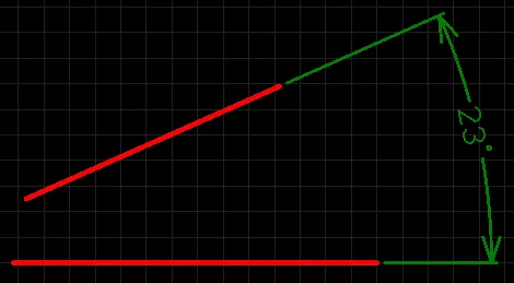
A placed Angular Dimension
An angular dimension allows for the dimensioning of angular distances.
Angular dimension objects are available for placement in both PCB and PCB Library Editors. After launching the angular dimension placement command, the cursor will change to a cross-hair and you will enter dimension placement mode. Placement is made by performing the following sequence of actions:
- Position the cursor over the first reference object then click or press Enter to anchor the first dimension reference (the inside reference).
- Move the cursor to the next required position associated with the first object being dimensioned then click or press Enter to anchor the second dimension reference (the outside reference).
- Position the cursor over the second reference object then click or press Enter to anchor the third dimension reference (the inside reference).
- Move the cursor to the next required position associated with the second object being dimensioned then click or press Enter to anchor the fourth dimension reference (the outside reference).
- Place the dimension text for the angle as desired then click or press Enter to complete placement.
- Continue placing further angular dimensions or right-click or press Esc to exit placement mode.
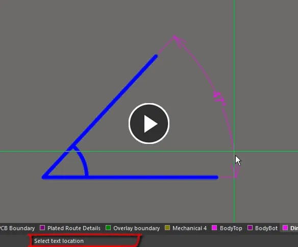
Additional actions that can be performed during placement are:
- Press the + and - keys (on the numeric keypad) to cycle forward and backward through all visible layers in the design to change placement layer quickly.
The graphical method of editing allows you to select a placed angular dimension object directly in the design space and change properties such as the position of its text and its reference points graphically.
When an angular dimension object is selected, the following editing handles are available:
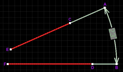
A selected Angular Dimension
- Click & drag A or B to change the position of the dimension text and extension line length.
- Click & drag C or E to detach the dimension from the first reference object.
- Click & drag D or F to detach the dimension from the second reference object.
C & E and D & F allow for redefinable references – once the dimension is detached from a reference object, it becomes non-referenced and can be moved for attachment to a different reference point or object.
- An angular dimension object can be moved in the following ways:
- Selecting both the dimension object and the objects that are being dimensioned - The whole can be dragged to a new location as required.
- Selecting an object that is being dimensioned only - The dimension text will follow the object in its alignment plane only. The dimension extensions will expand/contract to keep the relationship between dimension and object being dimensioned.
- Selecting the dimension object only - It is important to note that the dimension cannot be moved on its own if it is referenced by a design object. To move the dimension only, it must first be detached from the objects it is dimensioning.
- The dimension's value automatically updates as its start or end points are moved. Likewise, if the position of an object that a reference point of the dimension is anchored to is changed, the dimension will update and expand/contract to reflect this.
- If the angular dimension object is totally non-referenced (i.e. it is not attached to any reference design objects), click anywhere on it away from editing handles then drag to reposition it. While dragging, the angular dimension can be rotated or mirrored:
- Press the Spacebar to rotate the angular dimension counterclockwise or Shift+Spacebar for clockwise rotation. Rotation is in accordance with the value for the Rotation Step defined on the PCB Editor – General page of the Preferences dialog.
- Press the X or Y keys to mirror the angular dimension along the X-axis or Y-axis.
Angular Dimension Properties

The Angular Dimension mode of the Properties panel.
Style
- Width - the current dimension line width.
Extension Line
- Width - the current width for the dimension extension lines.
- Gap - the distance between a dimension extension line and the object being dimensioned.
- Offset - the current arrow line offset with respect to the dimension extension line.
- Text Gap - the current gap to the left and right of the dimension value text.
Arrow Style
- Arrow Size - the current arrowhead size. The size is measured as the distance between the arrow tip and the end of the arrow 'legs'.
- Arrow Length - the current arrow length. Note that the value entered into this field is applied only when the Arrow Position (in the Properties region) is set to Outside.
- Layer - the layer to which the dimension is currently assigned. Dimensions can be assigned to any available layer. Use the drop-down to select a different layer.
- Text Position - the current position of the dimension text. Use the associated drop-down list to choose one of the following options:
- Automatic - the dimension text will be placed in the most appropriate location with respect to the dimension so that the text itself is always readable.
- Aligned - Center - the dimension text will be aligned to the center of the dimension line.
- Aligned - Top - the dimension text will be aligned above the dimension line and centered.
- Aligned - Bottom - the dimension text will be aligned below the dimension line and centered.
- Aligned - Right - the dimension text will be aligned to the right of the dimension line (outside of the extension line).
- Aligned - Left - the dimension text will be aligned to the left of the dimension line (outside of the extension line).
- Aligned - Inside Right - the dimension text will be aligned to the right of the dimension line (inside the extension line).
- Aligned - Inside Left - the dimension text will be aligned to the left of the dimension line (inside the extension line).
- Unidirectional - the dimension text will be aligned to the center of the dimension line but will remain horizontal regardless of the dimension alignment angle.
- Manual - the dimension text will be available for manual placement directly in the design space.
- Arrow Position - the current position of the dimension arrows. The available options are:
- Inside - arrows will be positioned inside the dimension's extension lines (pointing outwards).
- Outside - arrows will be positioned outside the dimension's extension lines (pointing inwards).
- Text Height - the current height of the dimension text characters. The character width used to display or print the text is automatically proportioned to this height. A minimum height of 36mil (0.9mm) will allow the text to be legibly photo-plotted.
Font Type
- TrueType - use this field to choose the required TrueType font. The drop-down list is populated with TrueType and OpenType (a superset of TrueType) fonts found in the \Windows\Fonts folder. Note that the list will include only entries for detected (and uniquely named) root fonts. Use the B (bold) and I (Italic) options to add emphasis to the text.
- Stroke
- Font - use this field to choose the required Stroke font. Available options are:
- Default - a simple vector font that supports pen plotting and vector photo-plotting.
- Serif - a more complex font that will slow down vector output generation, such as Gerber.
- Sans Serif- a more complex font that will slow down vector output generation, such as Gerber.
Stroke-based fonts are built into the software and cannot be changed. All three fonts have the full IBM extended ASCII character set that supports English and other European languages.
Units
- Primary Units - the current unit that is selected for the calculation and display of the dimension value. Choose either Degrees (display the dimension value in Degrees/Minutes/Seconds) or Radians.
- Value Precision - the current setting for the number of decimal places to the right of the decimal point for which the dimension will be displayed.
Value
- Format - the current setting for the format of the dimension text. Use the associated drop-down to change the format as required. The options listed will depend on the chosen Unit and present based on the actual value for the current dimension. In generic terms, the available options are:
- None - no dimension text is displayed.
- Value Only - no units are displayed, only the dimension value (e.g., 45).
- Degrees Only - units of degrees are displayed after the dimension value (e.g., 45°).
- Degrees/Minutes - units of degrees and minutes are displayed after the dimension value (e.g., 45°12').
- Degrees/Minutes/Seconds - units of degrees/minutes/seconds are displayed after the dimension value (e.g., 45°12'0.61").
When the chosen unit is Radians, the available options are None and Value Only.
- Sample - this field presents a sample of how the dimension text will appear in accordance with the specified Format and any defined Prefix and/or Suffix.
- Prefix - the current prefix of the dimension value.
- Suffix - the current suffix of the dimension value.
Baseline Dimension

A placed Baseline Dimension
A baseline dimension allows for the dimensioning of a linear distance of a collection of references, relative to a single base reference. The first point chosen is the 'base'. All subsequent points are relative to this first point. The dimension value in each case is therefore the distance between each reference point and the 'base', measured in the default units. The references may be tracks, arcs, pads, vias, text, fills, polygons, or components.
Baseline dimension objects are available for placement in both PCB and PCB Library Editors. After launching the baseline dimension placement command, the cursor will change to a cross-hair and you will enter dimension placement mode. Placement is made by performing the following sequence of actions:
- Position the cursor and click or press Enter to anchor the dimension start point (this is the first reference point or 'base').
- Move the cursor to the required end point and click or press Enter to anchor the dimension end point (this is the second reference point).
- The text can now be initially positioned. Click or press Enter when the text is in the desired position to effect placement.
- Move the cursor to subsequent reference points and click or press Enter twice to effect placement (first click to anchor to a reference and second click after positioning the text).
- When all required references in the baseline dimension have been covered, right-click or press Esc to exit placement mode.
Additional actions that can be performed during placement are:
- Press the + and - keys (on the numeric keypad) to cycle forward and backward through all visible layers in the design respectively – to change placement layer quickly.
- Press Spacebar to rotate the dimension counterclockwise or Shift+Spacebar for clockwise rotation. Rotation is in accordance with the value for the Rotation Step defined on the PCB Editor – General page of the Preferences dialog.
The graphical method of editing allows you to select a placed baseline dimension object directly in the design space and change properties such as the position of its text and its reference points graphically.
When a baseline dimension object is selected, the following editing handles are available:
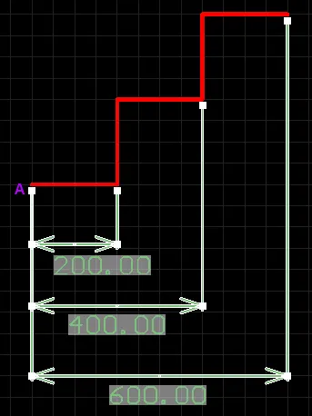
A selected Baseline Dimension
- Click and drag the handles at arrows to adjust the dimension text position parallel to the extensions.
- Click and drag A to move the base point of the dimension.
- Click and drag subsequent handles to move each reference individually, with respect to the base.
All handles nearest to the object(s) being dimensioned allow for re-definable references – once the dimension is detached from a reference object it becomes non-referenced and can be moved for attachment to a different reference point or object. As you drag any of the editing handles, the dimension may be rotated.
If the baseline dimension object is totally non-referenced (i.e. it is not attached to any reference design objects) click anywhere on it – away from editing handles – and drag to reposition it. While dragging, the baseline dimension can be rotated (Spacebar/Shift+Spacebar) or mirrored (X or Y keys to mirror along the X-axis or Y-axis respectively).
A baseline dimension object can be moved in the following ways:
- Selecting both the dimension object and the objects that are being dimensioned. The whole can be dragged to a new location as required.
- Selecting an object that is being dimensioned only. The dimension text will follow the object in its alignment plane only. The dimension extensions will expand/contract to keep the relationship between dimension and object being dimensioned.
- Selecting the dimension object only. It is important to note that the dimension cannot be moved on its own if it is referenced by a design object. To move the dimension only, it must first be detached from the objects it is dimensioning.
Baseline Dimension Properties
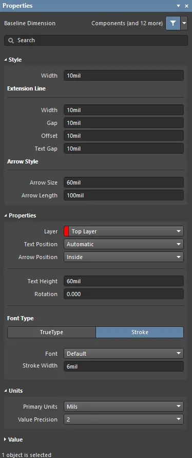
The Baseline Dimension mode of the Properties panel.
Style
- Width - the current dimension line width.
Extension Line
- Width - the current width for the dimension extension lines.
- Gap - the distance between a dimension extension line and the object being dimensioned.
- Offset - the current arrow line offset with respect to the dimension extension line.
- Text Gap - the current gap to the left and right of the dimension value text.
Arrow Style
- Arrow Size - the current arrowhead size. The size is measured as the distance between the arrow tip and the end of the arrow 'legs'.
- Arrow Length - the current arrow length. Note that the value entered into this field is applied only when the Arrow Position (in the Properties region) is set to Outside.
Properties
- Layer - the layer to which the dimension is currently assigned. Dimensions can be assigned to any available layer. Use the drop-down to select a different layer.
- Text Position - the current position of the dimension text. Use the associated drop-down list to choose one of the following options:
- Automatic - the dimension text will be placed in the most appropriate location with respect to the dimension so that the text itself is always readable.
- Aligned - Center - the dimension text will be aligned to the center of the dimension line.
- Aligned - Top - the dimension text will be aligned above the dimension line and centered.
- Aligned - Bottom - the dimension text will be aligned below the dimension line and centered.
- Aligned - Right - the dimension text will be aligned to the right of the dimension line (outside of the extension line).
- Aligned - Left - the dimension text will be aligned to the left of the dimension line (outside of the extension line).
- Aligned - Inside Right - the dimension text will be aligned to the right of the dimension line (inside the extension line).
- Aligned - Inside Left - the dimension text will be aligned to the left of the dimension line (inside the extension line).
- Unidirectional - the dimension text will be aligned to the center of the dimension line but will remain horizontal regardless of the dimension alignment angle.
- Manual - the dimension text will be available for manual placement directly in the design space.
- Arrow Position - the current position of the dimension arrows. The available options are:
- Inside - arrows will be positioned inside the dimension's extension lines (pointing outwards).
- Outside - arrows will be positioned outside the dimension's extension lines (pointing inwards).
- Text Height - the current height of the dimension text characters. The character width used to display or print the text is automatically proportioned to this height. A minimum height of 36mil (0.9mm) will allow the text to be legibly photo-plotted.
Font Type
- TrueType - use this field to choose the required TrueType font. The drop-down list is populated with TrueType and OpenType (a superset of TrueType) fonts found in the \Windows\Fonts folder. Note that the list will include only entries for detected (and uniquely named) root fonts. Use the B (bold) and I (Italic) options to add emphasis to the text.
- Stroke
- Font - use this field to choose the required Stroke font. Available options are:
- Default - a simple vector font that supports pen plotting and vector photo-plotting.
- Serif - a more complex font that will slow down vector output generation, such as Gerber.
- Sans Serif- a more complex font that will slow down vector output generation, such as Gerber.
Stroke-based fonts are built into the software and cannot be changed. All three fonts have the full IBM extended ASCII character set that supports English and other European languages.
Units
- Primary Units - the current unit that is selected for the calculation and display of the dimension value. Choose either Mils, Millimeters, Inches, Centimeters, or Automatic.
The
Automatic setting follows the actual measurement unit employed for the board as determined by the
Units setting in the
Other region of the
Properties panel in Board mode.
- Value Precision - the current setting for the number of decimal places to the right of the decimal point for which the dimension will be displayed.
Value
- Format - the current setting for the format of the dimension text. Use the associated drop-down to change the format as required. The options listed will depend on the chosen Unit and present based on the actual value for the current dimension. In generic terms, the available options are:
- None - no dimension text is displayed.
- Value Only - no units are displayed, only the dimension value (e.g., 600.00).
- Value and Unit - units are displayed after the dimension value (e.g., 600.00mil).
- Value and Bracketed Unit - units are displayed in brackets after the dimension value (e.g., 600.00 (mil)).
- Sample - this field presents a sample of how the dimension text will appear in accordance with specified Format and any defined Prefix and/or Suffix.
- Prefix - the current prefix of the dimension value.
- Suffix - the current suffix of the dimension value.
Center Dimension

A placed Center Dimension.
A center dimension is a group design object. It allows for the center of an arc or circle to be marked.
Center dimension objects are available for placement in both PCB and PCB Library Editors. After launching the center dimension placement command, the cursor will change to a cross-hair and you will enter dimension placement mode. Placement is made by performing the following sequence of actions:
- Position the cursor and click or press Enter to anchor the dimension to the desired arc or circle.
- Move the dimension until the desired sizing is achieved then click or press Enter to complete placement.
- Continue placing further center dimensions, or right-click or press Esc to exit placement mode.
Additional actions that can be performed during placement are:
- Press the + and - keys (on the numeric keypad) to cycle forward and backward through all visible layers in the design respectively – to change placement layer quickly.
- Press Spacebar to rotate the dimension counterclockwise or Shift+Spacebar for clockwise rotation. Rotation is in accordance with the value for the Rotation Step, defined on the PCB Editor – General page of the Preferences dialog.
The graphical method of editing allows you to select a placed center dimension object directly in the design space and change its size and orientation, graphically.
When a center dimension object is selected, the following editing handles are available:
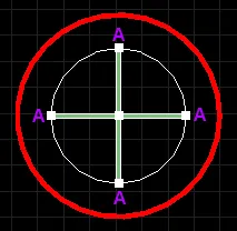
A selected Center Dimension.
- Click and drag A to change the size of the dimension. As you drag a handle, the dimension may be rotated (Spacebar/Shift+Spacebar).
A center dimension object can be moved in the following ways:
- Selecting both the dimension object and the circle/arc that is being dimensioned. The whole can be dragged to a new location as required.
- Selecting the circle/arc that is being dimensioned only. The dimension will move with the object.
Center Dimension Properties
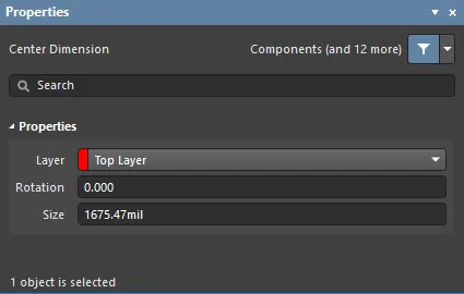
The Center Dimension mode of the Properties panel.
Properties
- Layer - the layer to which the dimension is currently assigned. Dimensions can be assigned to any available layer. Use the drop-down to select a different layer.
- Rotation - the angle of alignment of the dimension, measured counterclockwise in degrees from the horizontal.
- Size - the current length of the dimension's crosshair lines (or the diameter of the encompassing circle).
Leader Dimension
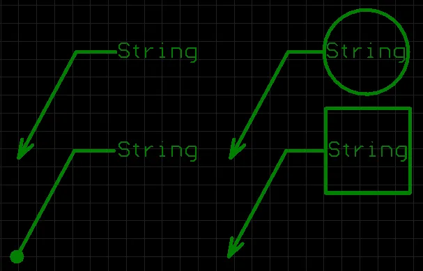
A placed Leader Dimensions
A leader dimension allows for the labeling of an object, point or area. There are three types of leader available: Automatic, Round and Square, which reflect the label text either being encapsulated in a circle or square or not at all. The pointer can be an arrow or a dot.
Leader dimension objects are available for placement in both PCB and PCB Library Editors. After launching the leader dimension placement command, the cursor will change to a cross-hair and you will enter dimension placement mode. Placement is made by performing the following sequence of actions:
- Position the cursor then click or press Enter to anchor the dimension start point (the location of the arrowhead or dot).
- Move the cursor then click or press Enter to anchor a series of vertex points that define the shape of the leader.
- After placing the final required vertex point, right-click or press Esc to effect placement of the text label and exit placement mode.
Additional actions that can be performed during placement are:
- Press the + and - keys (on the numeric keypad) to cycle forward and backward through all visible layers in the design to change placement layer quickly. Alternatively, use the Ctrl+Mouse Wheel shortcut to cycle through the available layers.
- Press Spacebar to toggle the dimensioning direction between horizontal and vertical.
This method of editing allows you to select a placed leader dimension object directly in the design space and change properties such as the position of its text, its shape and its reference point.
When a leader dimension object is selected, the following editing handles are available:
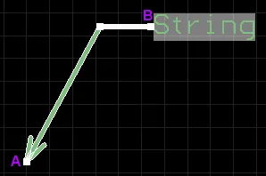
A selected Leader Dimension
- Click and drag A to move the start point of the dimension (i.e. the position of the arrowhead).
- Click and drag B to move the end point of the dimension (i.e. the position of the text label).
- Click and drag intermediate handles to change the shape of the leader.
Handle A allows for a re-definable reference; once the dimension is detached from a reference object, it becomes non-referenced and can be moved for attachment to a different reference point or object.
If the leader dimension object is totally non-referenced (i.e. it is not attached to a reference design object), click anywhere on it away from editing handles then drag to reposition it. While dragging, the leader dimension can be rotated or mirrored:
- Press the Spacebar to rotate the leader dimension counterclockwise or Shift+Spacebar for clockwise rotation. Rotation is in accordance with the value for the Rotation Step defined on the PCB Editor – General page of the Preferences dialog.
- Press the X or Y keys to mirror the leader dimension along the X-axis or Y-axis.
A leader dimension object can be moved in the following ways:
- Select both the dimension object and the object that is being dimensioned: the whole can be dragged to a new location as required.
- Select the object that is being dimensioned only: the dimension will follow the object. The segment of the leader dimension (between the arrow/dot and the first defined elbow) will expand/contract to keep the relationship between the dimension and the object being dimensioned.
- Select the dimension object only: it is important to note that the dimension cannot be moved on its own if it is referenced by a design object. To move the dimension only, it must first be detached from the object it is dimensioning.
Leader Dimension Properties
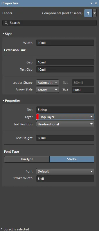
The Leader mode of the Properties panel.
Style
- Width - the current dimension line width.
Extension Line
- Gap - the current gap value, which is is the distance between the leader dimension arrow/dot and the object/point with which the leader is associated.
- Text Gap - the current gap between the dimension text and the last 'leg' of the leader line.
When the Leader Shape is set to Round or Square, this becomes the gap between the dimension text and the right-hand edge of the encapsulating shape. In this case, increasing the gap will actually bring the text closer to the end of the leader line.
- Leader Shape - use the drop-down to determine which shape is used to encapsulate the dimension text. Available options are Automatic, Round, and Square. If Round or Square are selected, enter the desired Size.
- Arrow Style - use the drop-down to select the desired leader style. Choices are Arrow or Dot. Enter the desired Size.
Properties
- Text - enter the desired text.
- Layer - the layer to which the dimension is currently assigned. Use the drop-down to select the desired layer. Dimensions can be assigned to any available layer.
- Text Position - the current position of the dimension text. Use the drop-down list to choose one of the following options:
- Aligned - Left - the dimension text will be aligned with the angle of the last 'leg' of the leader line.
- Unidirectional - the dimension text will remain horizontal regardless of the dimension alignment angle.
- Manual - the dimension text will be available for manual placement.
- Text Height - the current text height.
Font Type
- TrueType - use the drop-down to choose the required TrueType font. The drop-down list is populated with TrueType and OpenType (a superset of TrueType) fonts found in the \Windows\Fonts folder. Note that the list will only include entries for detected (and uniquely named) root fonts. Use the B (bold) and I (Italic) options to add emphasis to the text.
The use of TrueType fonts in PCB documents will result in more complex Gerber outputs.
To ensure all fonts used in your design are available wherever the design is loaded, enable the
Embed TrueType fonts inside PCB documents option on the
PCB Editor - TrueType Fonts page of the
Preferences dialog. A substitution TrueType font can also be nominated for files using TrueType fonts that are not installed locally.
- Stroke - stroke-based fonts are built into the software and cannot be changed. All three fonts have the full IBM extended ASCII character set that supports English and other European languages.
- Font - use the drop-down to choose the required Stroke font. Available options are Default, Serif, and Sans Serif. The Default style is a simple vector font that supports pen plotting and vector photo-plotting. The Sans Serif and Serif fonts are more complex and will slow down vector output generation, such as Gerber.
- Stroke Width - enter the desired width.
Linear Diameter Dimension
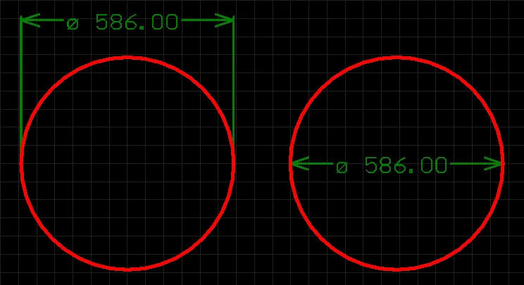
Placed Linear Diameter Dimensions.
A linear diameter dimension allows for the dimensioning of an arc or circle with respect to the diameter, rather than the radius. The dimension can be placed either internally or externally.
Linear diameter dimension objects are available for placement in both PCB and PCB Library Editors. After launching the linear diameter dimension placement command, the cursor will change to a cross-hair and you will enter dimension placement mode. Placement is made by performing the following sequence of actions:
- Position the cursor and click or press Enter to anchor the dimension to the desired arc or circle. The position of the dimension is determined by the alignment angle for the dimension.
- Move the dimension text to the desired position (either internal or external) and click or press Enter to complete placement.
- Continue placing further linear diameter dimensions, or right-click or press Esc to exit placement mode.
Additional actions that can be performed during placement are:
- Press the + and - keys (on the numeric keypad) to cycle forward and backward through all visible layers in the design respectively – to change placement layer quickly.
- Press Spacebar to rotate the dimension counterclockwise or Shift+Spacebar for clockwise rotation. Rotation is in accordance with the value for the Rotation Step, defined on the PCB Editor – General page of the Preferences dialog.
The graphical method of editing allows you to select a placed linear diameter dimension object directly in the design space and change properties such as the position of its text and its reference points, graphically.
When a linear diameter dimension object is selected, the following editing handles are available:
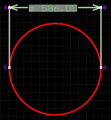
A selected Linear Diameter Dimension.
- Click and drag A or B to adjust the dimension text position parallel to the extensions.
- Click and drag C or D to detach the dimension from the reference object.
C & D allow for a redefinable reference – once the dimension is detached from a reference object it becomes non-referenced and can be moved for attachment to a different reference point or object.
If the linear diameter dimension object is totally non-referenced (i.e. it is not attached to a reference design object) click anywhere on it – away from editing handles – and drag to reposition it. While dragging, the linear diameter dimension can be rotated (Spacebar/Shift+Spacebar).
A linear diameter dimension object can be moved in the following ways:
- Selecting both the dimension object and the object that is being dimensioned. The whole can be dragged to a new location as required.
- Selecting the object that is being dimensioned only. The dimension text will follow the object in its alignment plane only. The dimension extensions will expand/contract to keep the relationship between dimension and object being dimensioned.
- Selecting the dimension object only. It is important to note that the dimension cannot be moved on its own if it is referenced by a design object. To move the dimension only, it must first be detached from the object it is dimensioning.
Linear Diameter Dimension Properties
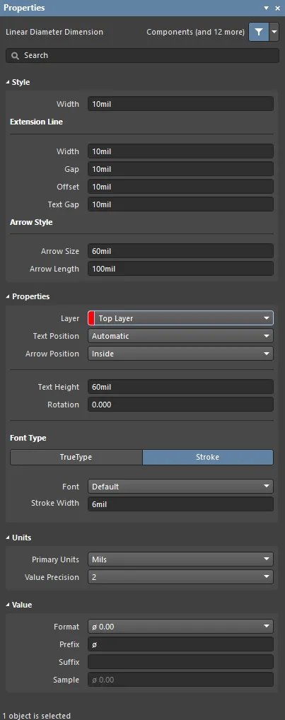
The Linear Diameter Dimension mode of the Properties panel.
Style
- Width - the current dimension line width.
Extension Line
- Width - the current width for the dimension extension lines.
- Gap - the distance between a dimension extension line and the object being dimensioned.
- Offset - the current arrow line offset with respect to the dimension extension line.
- Text Gap - the current gap to the left and right of the dimension value text.
Arrow Style
- Arrow Size - the current arrowhead size. The size is measured as the distance between the arrow tip and the end of the arrow 'legs'.
- Arrow Length - the current arrow length. Note that the value entered into this field is applied only when the Arrow Position (in the Properties region) is set to Outside.
Properties
- Layer - the layer to which the dimension is currently assigned. Dimensions can be assigned to any available layer. Use the drop-down to select a different layer.
- Text Position - the current position of the dimension text. Use the associated drop-down list to choose one of the following options:
- Automatic - the dimension text will be placed in the most appropriate location with respect to the dimension so that the text itself is always readable.
- Aligned - Center - the dimension text will be aligned to the center of the dimension line.
- Aligned - Top - the dimension text will be aligned above the dimension line and centered.
- Aligned - Bottom - the dimension text will be aligned below the dimension line and centered.
- Aligned - Right - the dimension text will be aligned to the right of the dimension line (outside of the extension line).
- Aligned - Left - the dimension text will be aligned to the left of the dimension line (outside of the extension line).
- Aligned - Inside Right - the dimension text will be aligned to the right of the dimension line (inside the extension line).
- Aligned - Inside Left - the dimension text will be aligned to the left of the dimension line (inside the extension line).
- Unidirectional - the dimension text will be aligned to the center of the dimension line but will remain horizontal regardless of the dimension alignment angle.
- Manual - the dimension text will be available for manual placement directly in the design space.
- Arrow Position - the current position of the dimension arrows. The available options are:
- Inside - arrows will be positioned inside the dimension's extension lines (pointing outwards).
- Outside - arrows will be positioned outside the dimension's extension lines (pointing inwards).
- Text Height - the current height of the dimension text characters. The character width used to display or print the text is automatically proportioned to this height. A minimum height of 36mil (0.9mm) will allow the text to be legibly photo-plotted.
- Rotation - the angle of alignment of the dimension, measured counterclockwise in degrees from the horizontal.
Font Type
- TrueType - use this field to choose the required TrueType font. The drop-down list is populated with TrueType and OpenType (a superset of TrueType) fonts found in the \Windows\Fonts folder. Note that the list will include only entries for detected (and uniquely named) root fonts. Use the B (bold) and I (italic) options to add emphasis to the text.
- Stroke
- Font - use this field to choose the required Stroke font. Available options are:
- Default - a simple vector font that supports pen plotting and vector photo-plotting.
- Serif - a more complex font that will slow down vector output generation, such as Gerber.
- Sans Serif- a more complex font that will slow down vector output generation, such as Gerber.
Stroke-based fonts are built into the software and cannot be changed. All three fonts have the full IBM extended ASCII character set that supports English and other European languages.
Units
- Primary Units - the current unit that is selected for the calculation and display of the dimension value. Choose either Mils, Millimeters, Inches, Centimeters, or Automatic.
The
Automatic setting follows the actual measurement unit employed for the board as determined by the
Units setting in the
Other region of the
Properties panel in Board mode.
- Value Precision - the current setting for the number of decimal places to the right of the decimal point for which the dimension will be displayed.
Value
- Format - the current setting for the format of the dimension text. Use the associated drop-down to change the format as required. The options listed will depend on the chosen Unit and present based on the actual value for the current dimension. In generic terms, the available options are:
- None - no dimension text is displayed.
- Value Only - no units are displayed, only the dimension value (e.g., ø 600.00).
- Value and Unit - units are displayed after the dimension value (e.g., ø 600.00mil).
- Value and Bracketed Unit - units are displayed in brackets after the dimension value (e.g., ø 600.00 (mil)).
For all formats other than None, the fixed prefix of ø is also displayed.
- Prefix - the prefix to the dimension value. This field is fixed with the character ø.
- Suffix - the current suffix of the dimension value.
- Sample - this field presents a sample of how the dimension text will appear in accordance with specified Format and any defined Prefix and/or Suffix.
Linear Dimension
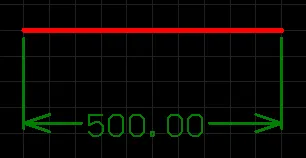
A placed Linear Dimension.
A linear dimension places dimensioning information on the current PCB layer, with respect to a linear distance. The dimension value is the distance between the start and end markers (reference points selected by the user) measured in the default units. The references may be objects (tracks, arcs, pads, vias, text, fills, polygons, or components) or points in free space.
Linear dimension objects are available for placement in both PCB and PCB Library Editors. After launching the linear dimension placement command, the cursor will change to a cross-hair and you will enter dimension placement mode. Placement is made by performing the following sequence of actions:
- Position the cursor then click or press Enter to anchor the dimension start point (this is the first reference point).
- Move the cursor then click or press Enter to anchor the dimension end point (this is the second reference point).
- The text can now be initially positioned. Move the cursor then click or press Enter when the text is in the desired position, to complete dimension placement.
- Continue placing further linear dimensions or right-click or press Esc to exit placement mode.
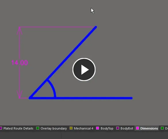
Additional actions that can be performed during placement are:
- Press the + and - keys (on the numeric keypad) to cycle forward and backward through all visible layers in the design to change placement layer quickly. Alternatively, use the Ctrl+Wheelroll shortcut to cycle through the available layers.
- Press Spacebar to toggle the dimensioning direction between horizontal and vertical.
The graphical method of editing allows you to select a placed linear dimension object directly in the design space and graphically change properties such as the position of its text and its reference points.
When a linear dimension object is selected, the following editing handles are available.
 A selected Linear Dimension
- Click & drag A or B to adjust the dimension text position and extension line length.
- Click & drag C or D to move the start or end reference points of the dimension.
C and D allow for redefinable references – once the dimension is detached from a reference object it becomes non-referenced and can be moved for attachment to a different reference point or object. As you drag any of the editing handles, the dimension may be rotated.
- A dimension object can be moved in the following ways:
- Selecting both the dimension object and the objects that are being dimensioned. The whole can be dragged to a new location as required.
- Selecting an object that is being dimensioned only. The dimension text will follow the object in its alignment plane only. The dimension extensions will expand/contract to keep the relationship between dimension and object being dimensioned.
- Selecting the dimension object only. It is important to note that the dimension cannot be moved on its own if it is referenced by a design object. To move the dimension only, it must first be detached from the objects it is dimensioning.
- The dimension's value automatically updates as its start or end points are moved. Likewise, if the position of an object that a reference point of the dimension is anchored to is changed, the dimension will update and expand/contract to reflect this.
- If the dimension object is totally non-referenced (i.e. it is not attached to any reference design objects) click anywhere on it away from editing handles then drag to reposition it. While dragging, the dimension can be rotated or mirrored:
- Press the Spacebar to rotate the dimension counterclockwise or Shift+Spacebar for clockwise rotation. Rotation is in accordance with the value for the Rotation Step defined on the PCB Editor – General page of the Preferences dialog.
- Press the X or Y keys to mirror the dimension along the X-axis or Y-axis respectively.
Linear Dimension Properties
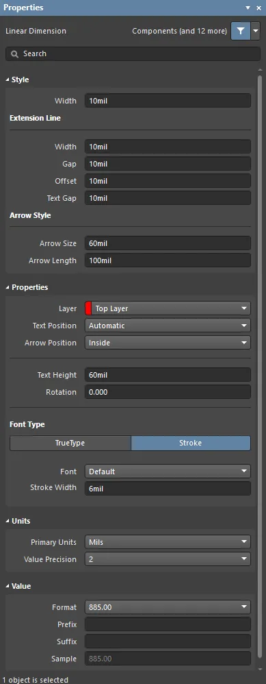
The Linear Dimension mode of the Properties panel.
Style
- Width - the current dimension line width.
Extension Line
- Width - the current width for the dimension extension lines.
- Gap - the distance between a dimension extension line and the object being dimensioned.
- Offset - the current line offset with respect to the dimension extension line.
- Text Gap - the current gap to the left and right of the dimension value text.
Arrow Style
- Arrow Size - the current arrowhead size. The size is measured as the distance between the arrow tip and the end of the arrow 'legs'.
- Arrow Length - the current arrow length. Note that the value entered into this field is applied only when the Arrow Position (in the Properties region) is set to Outside.
Properties
- Layer - the layer to which the dimension is currently assigned. Dimensions can be assigned to any available layer. Use the drop-down to select a different layer.
- Text Position - the current position of the dimension text. Use the associated drop-down list to choose one of the following options:
- Automatic - the dimension text will be placed in the most appropriate location with respect to the dimension so that the text itself is always readable.
- Aligned - Center - the dimension text will be aligned to the center of the dimension line.
- Aligned - Top - the dimension text will be aligned above the dimension line and centered.
- Aligned - Bottom - the dimension text will be aligned below the dimension line and centered.
- Aligned - Right - the dimension text will be aligned to the right of the dimension line (outside of the extension line).
- Aligned - Left - the dimension text will be aligned to the left of the dimension line (outside of the extension line).
- Aligned - Inside Right - the dimension text will be aligned to the right of the dimension line (inside the extension line).
- Aligned - Inside Left - the dimension text will be aligned to the left of the dimension line (inside the extension line).
- Unidirectional - the dimension text will be aligned to the center of the dimension line but will remain horizontal regardless of the dimension alignment angle.
- Manual - the dimension text will be available for manual placement directly in the design space.
- Arrow Position - the current position of the dimension arrows. The available options are:
- Inside - arrows will be positioned inside the dimension's extension lines (pointing outwards).
- Outside - arrows will be positioned outside the dimension's extension lines (pointing inwards).
- Text Height - the current height of the dimension text characters. The character width used to display or print the text is automatically proportioned to this height. A minimum height of 36mil (0.9mm) will allow the text to be legibly photo-plotted.
- Rotation - enter the number of degrees you'd like the dimension to rotate if desired.
Font Type
- TrueType - use this field to choose the required TrueType font. The drop-down list is populated with TrueType and OpenType (a superset of TrueType) fonts found in the \Windows\Fonts folder. Note, the list will only include entries for detected (and uniquely named) root fonts. Use the B (bold) and I (Italic) options to add emphasis to the text.
- Stroke
- Font - use this field to choose the required Stroke font. Available options are:
- Default - a simple vector font that supports pen plotting and vector photo-plotting.
- Serif - a more complex font that will slow down vector output generation, such as Gerber.
- Sans Serif- a more complex font that will slow down vector output generation, such as Gerber.
Stroke-based fonts are built into the software and cannot be changed. All three fonts have the full IBM extended ASCII character set that supports English and other European languages.
Units
- Primary Units - the current unit that is selected for the calculation and display of the dimension value. Choose either Mils, Millimeters, Inches, Centimeters, or Automatic.
The
Automatic setting follows the actual measurement unit employed for the board as determined by the
Units setting in the
Other region of the
Properties panel in Board mode.
- Value Precision - the current setting for the number of decimal places to the right of the decimal point for which the dimension will be displayed.
Value
- Format - the current setting for the format of the dimension text. Use the associated drop-down to change the format as required. The options listed will depend on the chosen Unit and present based on the actual value for the current dimension. In generic terms, the available options are:
- None - no dimension text is displayed.
- Value Only - no units are displayed, only the dimension value (e.g., 600.00).
- Value and Unit - units are displayed after the dimension value (e.g., 600.00mil).
- Value and Bracketed Unit - units are displayed in brackets after the dimension value (e.g., 600.00 (mil)).
- Prefix - the current prefix to the dimension value.
- Suffix - the current suffix to the dimension value.
- Sample - this field presents a sample of how the dimension text will appear in accordance with specified Format and any defined Prefix and/or Suffix.
Ordinate Dimension
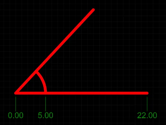
A placed Ordinate Dimension
An ordinate dimension allows for the dimensioning of a linear distance of a collection of objects relative to a single reference object. The first object chosen is the 'base'. All subsequent objects are relative to this first object. The dimension value in each case is, therefore, the distance between each reference object and the 'base' measured in the default units. The references may be tracks, arcs, pads, vias, text, fills, polygons, or components.
Ordinate dimension objects are available for placement in both PCB and PCB Library Editors. After launching the ordinate dimension placement command, the cursor will change to a cross-hair and you will enter dimension placement mode. Placement is made by performing the following sequence of actions:
- Position the cursor then click or press Enter to anchor the dimension start point (this is the first reference object or 'base').
- Move the cursor to the next required object then click or press Enter to anchor the dimension end point (this is the second reference object).
- Move the cursor to subsequent reference objects then click or press Enter. When all desired objects have been selected, right-click or press Esc.
- The text can now be initially positioned. Click or press Enter when the text is in the desired position to complete placement and exit placement mode.
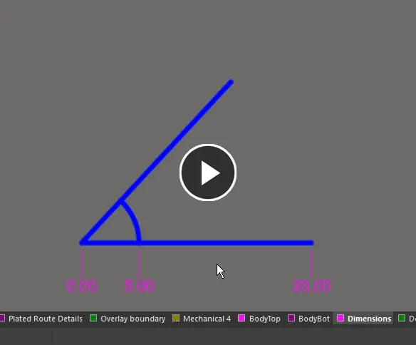
Additional actions that can be performed during placement are:
- Press the + and - keys (on the numeric keypad) to cycle forward and backward through all visible layers in the design to change placement layer quickly. Alternatively, use the Ctrl+Wheelroll shortcut to cycle through the available layers.
- Press Spacebar to toggle the dimensioning direction between horizontal and vertical.
The graphical method of editing allows you to select a placed ordinate dimension object directly in the design space and graphically change properties such as the position of its text and its reference points.
When an ordinate dimension object is selected, the following editing handles are available.
 A selected Ordinate Dimension
- Click & drag handle A to move the dimension text.
- Click & drag the handles at B to move that reference individually with respect to the base.
All handles nearest to the object(s) being dimensioned allow for redefinable references – once the dimension is detached from a reference object it becomes non-referenced and can be moved for attachment to a different reference point or object. As you drag any of the editing handles, the dimension may be rotated.
- A dimension object can be moved in the following ways:
- Selecting both the dimension object and the objects that are being dimensioned. The whole can be dragged to a new location as required.
- Selecting an object that is being dimensioned only. The dimension text will follow the object in its alignment plane only. The dimension extensions will expand/contract to keep the relationship between dimension and object being dimensioned.
- Selecting the dimension object only. It is important to note that the dimension cannot be moved on its own if it is referenced by a design object. To move the dimension only, it must first be detached from the objects it is dimensioning.
- The dimension's value automatically updates as its start or end points are moved. Likewise, if the position of an object that a reference point of the dimension is anchored to is changed, the dimension will update and expand/contract to reflect this.
- If the dimension object is totally non-referenced (i.e. it is not attached to any reference design objects), click anywhere on it away from editing handles then drag to reposition it. While dragging, the dimension can be rotated or mirrored:
- Press the Spacebar to rotate the dimension counterclockwise or Shift+Spacebar for clockwise rotation. Rotation is in accordance with the value for the Rotation Step defined on the PCB Editor – General page of the Preferences dialog.
- Press the X or Y keys to mirror the dimension along the X-axis or Y-axis.
Ordinate Dimension Properties

The Ordinate Dimension mode of the Properties panel.
Style
- Extension Line Width - the current width for the dimension extension lines.
- Gap - the distance between a dimension extension line and the object being dimensioned.
- Text Gap - the current gap to the left and right of the dimension value text.
Properties
- Layer - the layer to which the dimension is currently assigned. Dimensions can be assigned to any available layer. Use the drop-down to select a different layer.
- Text Position - the current position of the dimension text. Use the associated drop-down list to choose one of the following options:
- Aligned - Left - the dimension text will be aligned with the angle of the dimension line.
- Unidirectional - the dimension text will remain horizontal regardless of the dimension alignment angle.
- Manual - the dimension text will be available for manual placement.
- Text Height - the current height of the dimension text characters. The character width used to display or print the text is automatically proportioned to this height. A minimum height of 36mil (0.9mm) will allow the text to be legibly photo-plotted.
- Rotation - the angle of alignment of the dimension, measured counterclockwise in degrees from the horizontal.
Font Type
- TrueType - use this field to choose the required TrueType font. The drop-down list is populated with TrueType and OpenType (a superset of TrueType) fonts found in the \Windows\Fonts folder. Note that the list will include only entries for detected (and uniquely named) root fonts. Use the B (bold) and I (italic) options to add emphasis to the text.
- Stroke
- Font - use this field to choose the required Stroke font. Available options are:
- Default - a simple vector font that supports pen plotting and vector photo-plotting.
- Serif - a more complex font that will slow down vector output generation, such as Gerber.
- Sans Serif - a more complex font that will slow down vector output generation, such as Gerber.
Stroke-based fonts are built into the software and cannot be changed. All three fonts have the full IBM extended ASCII character set that supports English and other European languages.
Units
- Primary Units - the current unit that is selected for the calculation and display of the dimension value. Choose either Mils, Millimeters, Inches, Centimeters, or Automatic.
The
Automatic setting follows the actual measurement unit employed for the board, as determined by the
Units setting in the
Other region of the
Properties panel in Board mode.
- Value Precision - the current setting for the number of decimal places to the right of the decimal point for which the dimension will be displayed.
Value
- Format - the current setting for the format of the dimension text. Use the associated drop-down to change the format as required. The options listed will depend on the chosen Unit and present based on the actual value for the current dimension. In generic terms, the available options are:
- None - no dimension text is displayed.
- Value Only - no units are displayed, only the dimension value (e.g., 600.00).
- Value and Unit - units are displayed after the dimension value (e.g., 600.00mil).
- Value and Bracketed Unit - units are displayed in brackets after the dimension value (e.g., 600.00 (mil)).
- Sample - this field presents a sample of how the dimension text will appear in accordance with specified Format and any defined Prefix and/or Suffix.
- Prefix - the current prefix to the dimension value.
- Suffix - the current suffix to the dimension value.
Radial Diameter Dimension
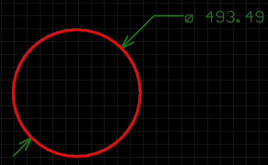
A placed Radial Diameter dimension.
A radial diameter dimension allows for the dimensioning of an arc or circle with respect to the diameter, rather than the radius. The dimension can be placed either internally or externally, in relation to the circumference of the arc/circle.
Radial Diameter dimension objects are available for placement in both PCB and PCB Library Editors. After launching the radial diameter dimension placement command, the cursor will change to a cross-hair and you will enter dimension placement mode. Placement is made by performing the following sequence of actions:
- Position the cursor and click or press Enter to anchor the dimension to the desired arc or circle.
- Move the dimension's arrow pointer to the desired location around the arc or circle. The arrow can be placed either inside or outside and movement is in accordance with the Arrow Position value in the Radial Diameter Dimension properties panel. When the required position has been attained, click or press Enter to lock the arrow in place.
- The text can now be initially positioned in relation to the tail of the arrow pointer. Move the text into the required position and click or press Enter to complete placement.
- Continue placing further radial diameter dimensions, or right-click or press Esc to exit placement mode.
Additional actions that can be performed during placement are:
- Press the + and - keys (on the numeric keypad) to cycle forward and backward through all visible layers in the design respectively – to change placement layer quickly.
This method of editing allows you to select a placed radial diameter dimension object directly in the design space and change properties such as the position of its text and its reference point, graphically.
When a radial diameter dimension object is selected, the following editing handles are available:

A selected Radial Diameter Dimension.
- Click and drag A to adjust the leader position, relative to the 'tail' of the arrow pointer.
- Click and drag B to adjust the position of the arrow pointer around the circumference of the circle or arc or change the length of the arrow leader line.
- Click and drag C to move the start point of the dimension.
Handle C allows you to redefine the reference – once the dimension is detached from a reference object it becomes non-referenced and can be moved for attachment to a different reference object.
If the dimension text is placed within the circumference of the arc or circle, only two of the three editing handles will be available for use – A and C. Editing handle A will assume the additional role of editing handle B.
If the radial diameter dimension object is totally non-referenced (i.e. it is not attached to a reference design object) click anywhere on it – away from editing handles – and drag to reposition it. While dragging, the radial diameter dimension can be rotated or mirrored:
- Press the Spacebar to rotate the radial diameter dimension counterclockwise or Shift+Spacebar for clockwise rotation. Rotation is in accordance with the value for the Rotation Step defined on the PCB Editor – General page of the Preferences dialog.
- Press the X or Y keys to mirror the radial diameter dimension along the X-axis or Y-axis respectively.
A radial diameter dimension object can be moved in the following ways:
- Selecting both the dimension object and the object that is being dimensioned. The whole can be dragged to a new location as required.
- Selecting the object that is being dimensioned only. The dimension text will follow the object in its alignment plane only. The dimension pointer and tail will expand/contract to keep the relationship between dimension and object being dimensioned.
- Selecting the dimension object only. It is important to note that the dimension cannot be moved on its own if it is referenced by a design object. To move the dimension only, it must first be detached from the object it is dimensioning.
Radial Diameter Dimension Properties
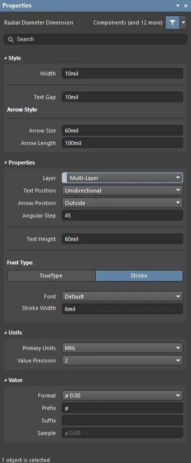
The Radial Diameter Dimension mode of the Properties panel.
Style
- Width - the current dimension line width.
- Text Gap - the current gap to the left and right of the dimension value text.
Arrow Style
- Arrow Size - the current arrowhead size. The size is measured as the distance between the arrow tip and the end of the arrow 'legs'.
- Arrow Length - the current arrow length. Note that the value entered into this field is applied only when the Arrow Position (in the Properties region) is set to Outside.
Properties
- Layer - the layer to which the dimension is currently assigned. Dimensions can be assigned to any available layer. Use the drop-down to select a different layer.
- Text Position - the current position of the dimension text. Use the associated drop-down list to choose one of the following options:
- Aligned - Left - the dimension text will be aligned to the left of the dimension line (outside of the extension line).
- Unidirectional - the dimension text will be aligned to the center of the dimension line but will remain horizontal regardless of the dimension alignment angle.
- Manual - the dimension text will be available for manual placement directly in the design space.
- Arrow Position - the current position of the dimension arrows. The available options are:
- Inside - arrows will be positioned inside the dimension's extension lines (pointing outwards).
- Outside - arrows will be positioned outside the dimension's extension lines (pointing inwards).
- Angular Step - the current angular step setting for the dimension. This is the rotation step used when placing the arrow portion of the dimension. Moving the arrow around the circle or arc during placement of the dimension, the number and position of possible places to anchor the dimension are determined by this angular step value.
- Text Height - the current height of the dimension text characters. The character width used to display or print the text is automatically proportioned to this height. A minimum height of 36mil (0.9mm) will allow the text to be legibly photo-plotted.
Font Type
- TrueType - use this field to choose the required TrueType font. The drop-down list is populated with TrueType and OpenType (a superset of TrueType) fonts found in the \Windows\Fonts folder. Note that the list will include only entries for detected (and uniquely named) root fonts. Use the B (bold) and I (Italic) options to add emphasis to the text.
- Stroke
- Font - use this field to choose the required Stroke font. Available options are:
- Default - a simple vector font that supports pen plotting and vector photo-plotting.
- Serif - a more complex font that will slow down vector output generation, such as Gerber.
- Sans Serif- a more complex font that will slow down vector output generation, such as Gerber.
Stroke-based fonts are built into the software and cannot be changed. All three fonts have the full IBM extended ASCII character set that supports English and other European languages.
Units
- Primary Units - the current unit that is selected for the calculation and display of the dimension value. Choose either Mils, Millimeters, Inches, Centimeters, or Automatic.
The
Automatic setting follows the actual measurement unit employed for the board as determined by the
Units setting in the
Other region of the
Properties panel in Board mode.
- Value Precision - the current setting for the number of decimal places to the right of the decimal point for which the dimension will be displayed.
Value
- Format - the current setting for the format of the dimension text. Use the associated drop-down to change the format as required. The options listed will depend on the chosen Unit and present based on the actual value for the current dimension. In generic terms, the available options are:
- None - no dimension text is displayed.
- Value Only - no units are displayed, only the dimension value (e.g., ø 600.00).
- Value and Unit - units are displayed after the dimension value (e.g., ø 600.00mil).
- Value and Bracketed Unit - units are displayed in brackets after the dimension value (e.g., ø 600.00 (mil)).
For all formats other than None, the fixed prefix of ø is also displayed.
- Prefix - the prefix to the dimension value. This field is fixed with the character ø.
- Suffix - the current suffix of the dimension value.
- Sample - this field presents a sample of how the dimension text will appear in accordance with specified Format and any defined Prefix and/or Suffix.
Radial Dimension

A placed Radial Dimension.
A radial dimension allows for the dimensioning of a radius with respect to an arc or circle. The dimension can be placed either internally or externally.
Radial dimension objects are available for placement in both PCB and PCB Library Editors. After launching the radial dimension placement command, the cursor will change to a cross-hair and you will enter dimension placement mode. Placement is made by performing the following sequence of actions:
- Position the cursor then click or press Enter to anchor the dimension to the desired arc or circle.
- Move the dimension's arrow pointer to the desired location around the arc or circle. The arrow can be placed either inside or outside and movement is in accordance with the Angular Step value in the Radial Dimension mode of the Properties panel. When the required position has been attained, click or press Enter to lock the arrow in place.
- The text can now be initially positioned in relation to the tail of the arrow pointer. Move the text into the required position then click or press Enter to complete placement.
- Continue placing further radial dimensions or right-click or press Esc to exit dimension placement mode.
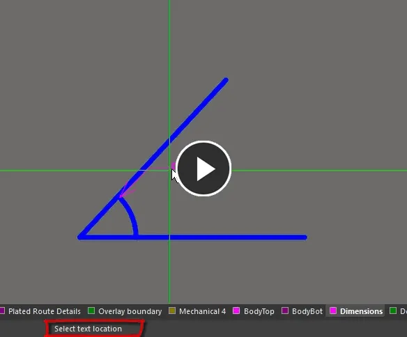
Additional actions that can be performed during placement are:
- Press the + and - keys (on the numeric keypad) to cycle forward and backward through all visible layers in the design to change the placement layer quickly. Alternatively, use the Ctrl+Wheelroll shortcut to cycle through the available layers.
This method of editing allows you to select a placed radial dimension object directly in the design space and graphically change properties such as the position of its text, the location of its arrow pointer, and its reference point.
When a radial dimension object is selected, the following editing handles are available:

A selected Radial Dimension
- Click & drag A to adjust the dimension text position relative to the 'tail' of the arrow pointer.
- Click & drag B to adjust the position of the arrow pointer around the circumference of the circle or arc.
- Click & drag C to move the start point of the dimension.
Handle C allows you to redefine the reference; once the dimension is detached from a reference object it becomes non-referenced and can be moved for attachment to a different reference object.
If the dimension text is placed within the circumference of the arc or circle, only two of the three editing handles will be available for use – A and C. Editing handle A will assume the additional role of editing handle B.
- A dimension object can be moved in the following ways:
- Selecting both the dimension object and the objects that are being dimensioned. The whole can be dragged to a new location as required.
- Selecting an object that is being dimensioned only. The dimension text will follow the object in its alignment plane only. The dimension extensions will expand/contract to keep the relationship between dimension and object being dimensioned.
- Selecting the dimension object only. It is important to note that the dimension cannot be moved on its own if it is referenced by a design object. To move the dimension only, it must first be detached from the objects it is dimensioning.
- The dimension's value automatically updates as the radius of the reference arc or circle changes.
- If the dimension object is totally non-referenced (i.e. it is not attached to any reference design objects) click anywhere on it away from editing handles then drag to reposition it. While dragging, the dimension can be rotated or mirrored:
- Press the Spacebar to rotate the dimension counterclockwise or Shift+Spacebar for clockwise rotation. Rotation is in accordance with the value for the Rotation Step defined on the PCB Editor – General page of the Preferences dialog.
- Press the X or Y keys to mirror the radial dimension along the X-axis or Y-axis.
Radial Dimension Properties
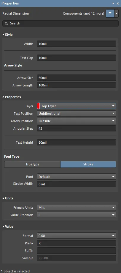
The Radial Dimension mode of the Properties panel.
Style
- Width - the current dimension line width.
- Text Gap - the current gap to the left and right of the dimension value text.
Arrow Style
- Arrow Size - the current arrowhead size. The size is measured as the distance between the arrow tip and the end of the arrow 'legs'.
- Arrow Length - the current arrow length. Note that the value entered into this field is applied only when the Arrow Position (in the Properties region) is set to Outside.
Properties
- Layer - the layer to which the dimension is currently assigned. Dimensions can be assigned to any available layer. Use the drop-down to select a different layer.
- Text Position - the current position of the dimension text. Use the associated drop-down list to choose one of the following options:
- Aligned - Left - the dimension text will be aligned with the angle of the dimension line.
- Unidirectional - the dimension text will remain horizontal regardless of the dimension alignment angle.
- Manual - the dimension text will be available for manual placement.
- Arrow Position - the current position of the dimension arrows. The available options are:
- Inside - arrows will be positioned inside the dimension's extension lines (pointing outwards).
- Outside - arrows will be positioned outside the dimension's extension lines (pointing inwards).
- Text Height - the current height of the dimension text characters. The character width used to display or print the text is automatically proportioned to this height. A minimum height of 36mil (0.9mm) will allow the text to be legibly photo-plotted.
Font Type
- TrueType - use this field to choose the required TrueType font. The drop-down list is populated with TrueType and OpenType (a superset of TrueType) fonts found in the \Windows\Fonts folder. Note that the list will only include entries for detected (and uniquely named) root fonts. Use the B (bold) and I (italic) options to add emphasis to the text.
- Stroke
- Font - use this field to choose the required Stroke font. Available options are:
- Default - a simple vector font that supports pen plotting and vector photo-plotting.
- Serif - a more complex font that will slow down vector output generation, such as Gerber.
- Sans Serif - a more complex font that will slow down vector output generation, such as Gerber.
Stroke-based fonts are built into the software and cannot be changed. All three fonts have the full IBM extended ASCII character set that supports English and other European languages.
Units
- Primary Units - the current unit that is selected for the calculation and display of the dimension value.
The
Automatic setting follows the actual measurement unit employed for the board as determined by the
Units setting in the
Other region of the
Properties panel in Board mode.
- Value Precision - the current setting for the number of decimal places to the right of the decimal point for which the dimension will be displayed.
Value
- Format - the current setting for the format of the dimension text. Use the associated drop-down to change the format as required. The options listed will depend on the chosen Unit and present based on the actual value for the current dimension. In generic terms, the available options are:
- None - no dimension text is displayed.
- Value Only - no units are displayed, only the dimension value (e.g., 600.00).
- Value and Unit - units are displayed after the dimension value (e.g., 600.00mil).
- Value and Bracketed Unit - units are displayed in brackets after the dimension value (e.g., 600.00(mil)).
- Prefix - the current prefix to the dimension value.
- Suffix - the current suffix to the dimension value.
- Sample - this field presents a sample of how the dimension text will appear in accordance with specified Format and any defined Prefix and/or Suffix.
Standard Dimension

A placed Standard Dimension
A standard dimension places dimensioning information on the current PCB layer. The dimension value is the distance between the start and end markers measured in the default units.
The Standard Dimension is considered a legacy dimensioning tool, superseded with the enhanced functionality provided by the linear and other dimension objects.
Standard dimension objects are available for placement in both PCB and PCB Library Editors. After launching the standard dimension placement command, the cursor will change to a cross-hair and you will enter dimension placement mode. Placement is made by performing the following sequence of actions:
- Position the cursor then click or press Enter to anchor the dimension start point.
- Move the cursor to the required end point, then click or press Enter to anchor the point and complete placement.
- Continue placing further standard dimensions or right-click or press Esc to exit placement mode.
Additional actions that can be performed during placement are:
- Press the L key to flip the dimension to the other side of the board – note that this is only possible prior to anchoring the dimension's start point.
- Press the + and - keys (on the numeric keypad) to cycle forward and backward through all visible layers in the design to change placement layer quickly.
This method of editing allows you to select a placed Standard dimension object directly in the design space and change its location, orientation and position of its start and end points.
When a Standard dimension object is selected, the following editing handles are available:

A selected Standard Dimension
- Click & drag A to move the start point of the dimension.
- Click & drag B to move the end point of the dimension.
- Click anywhere on the dimension away from editing handles and drag to reposition it. While dragging, the standard dimension can be rotated or mirrored:
- Press the Spacebar to rotate the Standard dimension counterclockwise or Shift+Spacebar for clockwise rotation. Rotation is in accordance with the value for the Rotation Step defined on the PCB Editor – General page of the Preferences dialog.
- Press the X or Y keys to mirror the Standard dimension along the X-axis or Y-axis.
Standard Dimension Properties
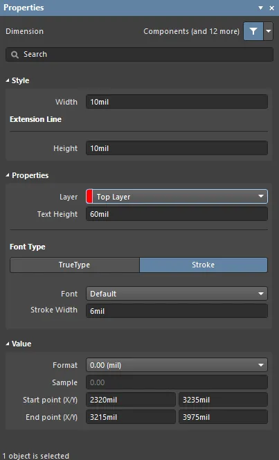
The Standard Dimension mode of the Properties panel.
Style
- Width - the current dimension line width.
Extension Line
- Height - the current extension line height.
Properties
- Layer - the layer to which the dimension is currently assigned. Dimensions can be assigned to any available layer. Use the drop-down to select a different layer.
- Text Height - the current height of the dimension text characters. The character width used to display or print the text is automatically proportioned to this height. A minimum height of 36mil (0.9mm) will allow the text to be legibly photo-plotted.
Font Type
- TrueType - use this field to choose the required TrueType font. The drop-down list is populated with TrueType and OpenType (a superset of TrueType) fonts found in the \Windows\Fonts folder. Note, the list will only include entries for detected (and uniquely named) root fonts. Use the B (bold) and I (italic) options to add emphasis to the text.
- Stroke
- Font - use this field to choose the required Stroke font. Available options are:
- Default - a simple vector font that supports pen plotting and vector photo-plotting.
- Serif - a more complex font that will slow down vector output generation, such as Gerber.
- Sans Serif - a more complex font that will slow down vector output generation, such as Gerber.
Stroke-based fonts are built into the software and cannot be changed. All three fonts have the full IBM extended ASCII character set that supports English and other European languages.
Value
- Format - the current setting for the format of the dimension text. Use the associated drop-down to change the format as required. The options listed will depend on the chosen Unit and present based on the actual value for the current dimension. In generic terms, the available options are:
- None - no dimension text is displayed.
- Value Only - no units are displayed, only the dimension value (e.g., 600.00).
- Value and Unit - units are displayed after the dimension value (e.g., 600.00mil).
- Value and Bracketed Unit - units are displayed in brackets after the dimension value (e.g., 600.00(mil)).
- Sample - this field presents a sample of how the dimension text will appear in accordance with specified Format and any defined Prefix and/or Suffix.
- Start point (X/Y) - the start point of the dimension for X (first value) and Y (second value).
- End point (X/Y) - the end point of the dimension for X (first value) and Y (second value).
