親ページ: ActiveBOMでのBOM管理
BOMドキュメントの作成
ActiveBOMの作業用BOMドキュメントはBomDocと呼ばれます。プロジェクトに新しいBomDocを追加するには、File » Newサブメニューを使用するか、プロジェクトパネル内のプロジェクトを右クリックします。プロジェクトに少なくとも1つのコンポーネントがある場合、プロジェクト構造内のActiveBOMエントリの隣にある+ Createコントロールをクリックすることで新しいBomDocを作成できます。各PCBプロジェクトはBomDocを1つしか含めることができないことに注意してください。
プロジェクトに新しいBomDocを追加すると、回路図が自動的にコンパイルされ、既存のすべてのコンポーネントがBomDocにリストされます。パーツ選択を含むワークスペースライブラリコンポーネントの場合、解決策はインターフェースの下部に詳細に説明されます。これは、下記の解決策の理解セクションで説明されています。
追加のコンポーネントが回路図に配置されると、それらは自動的にBomDocに追加されます。追加のBOMアイテムや追加のパラメータも、コンポーネントリストの上にあるAdd newボタンを介して、ActiveBOMで直接手動で追加することができます。カスタムBOMアイテムと列セクションを参照して、詳細を学んでください。
BOMアイテムリスト
BomDocの上部領域は、PCB設計プロジェクトで検出されたすべてのコンポーネント、およびBomDocに直接追加した追加のBOMアイテムの表形式のリストです。この領域はBOMアイテムリストと呼ばれます。
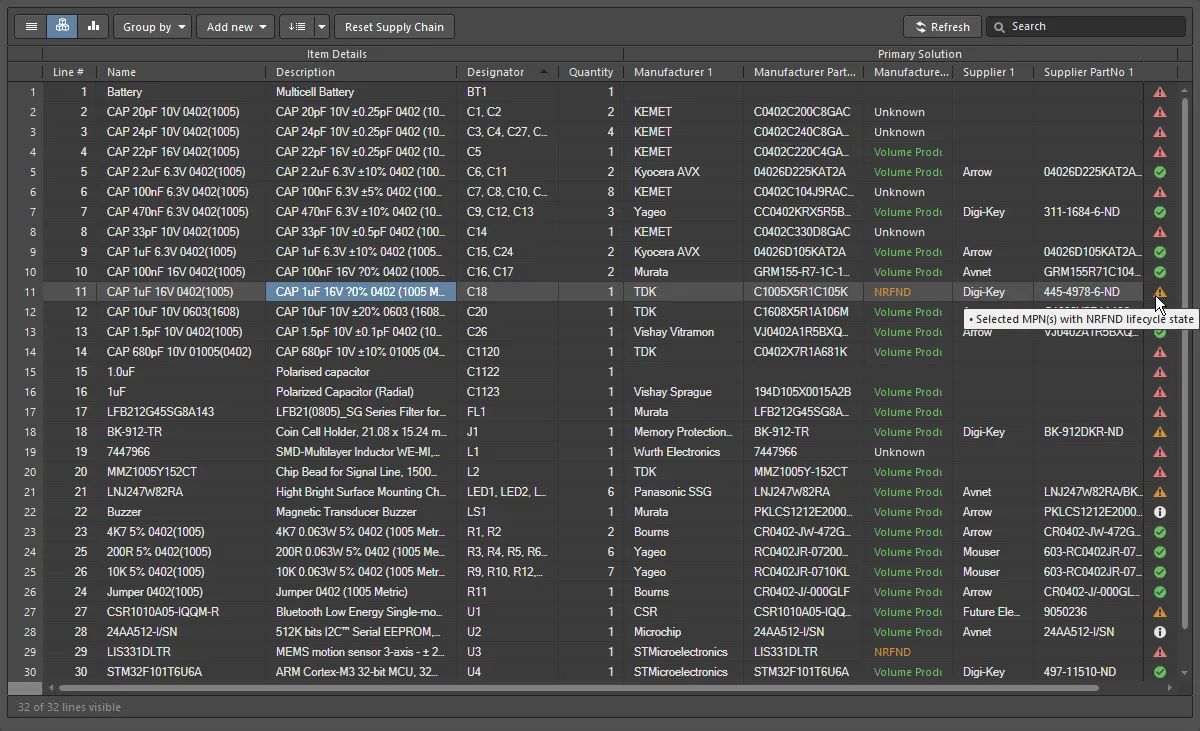
基本ビューに表示されるコンポーネント、またはBOMアイテムリスト。
BOMアイテムを表示するための3つのビューモードがあります。リストの上にあるボタンを使用して、必要なモードを選択してください:
 Flat view - 各コンポーネントごとに1行。
 Base view - プロジェクト内の各ユニークなコンポーネントに対して一行、デザイネータ列にはこのタイプのすべてのコンポーネントのデザイネータがリストされます。グループ化されたデザイネータには、複数の表示オプションが用意されています。Propertiesパネルで必要なDesignator Groupingモードを選択します。
 Consolidated view - プロジェクトにバリアントが含まれている場合、すべてのバリアントの統合BOMを表示するために使用されます。
同一コンポーネントの識別
BaseビューとConsolidatedビューで同一のコンポーネントをグループ化するために、ActiveBOMは以下のメカニズムを使用します:
-
Workspaceライブラリコンポーネントの場合 - DesignItemIDによって。
-
Workspaceライブラリ以外のコンポーネントの場合 - DesignItemIDとLibrary Nameによって、さらにComponent Groupingダイアログで有効にされたコンポーネントパラメータによっても識別します。このアプローチにより、設計者はライブラリに汎用のWorkspaceライブラリ以外のコンポーネントを作成し、配置された後に特定のコンポーネントの詳細を追加することができます。Component Groupingダイアログでデフォルトで有効にされているパラメータはComment、Description、Valueです。ActiveBOMのPropertiesパネルでコンポーネントグルーピングEditボタンをクリックすると、ダイアログが開きます。このボタンは、デザインにWorkspaceライブラリ以外のコンポーネントがある場合にのみ利用可能です。
コンポーネントグルーピングについての注意点:
-
Component Groupingダイアログは、同一のコンポーネントを識別してグループ化するために使用されます。PCBコンポーネントのプロパティなど、他のパラメータ/プロパティもComponent Groupingダイアログにリストされることがありますが、同一のコンポーネントを定義するために使用できるのはコンポーネントパラメータのみです。
-
BomDocやカスタムBOMでコンポーネントを何らかの目的でグループ化したい場合、例えばトップサイドコンポーネントとボトムサイドコンポーネントをグループ化する場合は、リストビューに切り替えてからActiveBOMのGroup byボタンを使用するか(画像を表示)、Report Manager の列グルーピング機能を使用します(画像を表示)。ActiveBOMのGroup byドロップダウンリストにあるパラメータは、PropertiesパネルのColumnsタブで現在表示に設定されているパラメータです。
カラムグループ
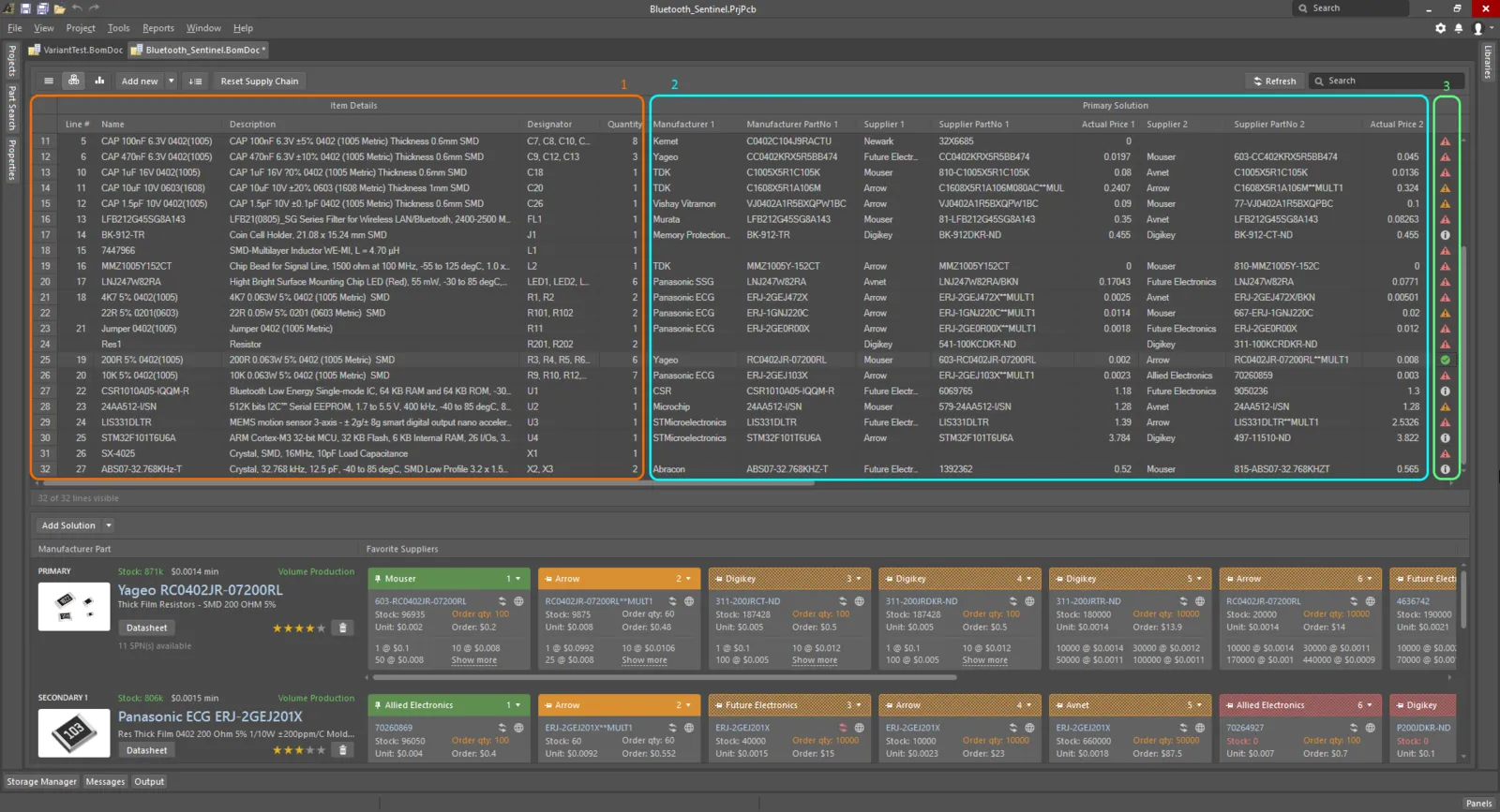
ActiveBOMコンポーネントリストには、各ビューモードに表示される異なるカラムグループがあります。上の画像はベースビューを示しています。
BOMアイテムグリッドは、以下の主要なグループに分類されます:
-
Details(画像内のオレンジ色のハイライト)- これらの列には、デザイネータ、説明、ライブラリ参照、その他のコンポーネントパラメータなど、パラメトリックコンポーネントの詳細が表示されます。
-
Solutions(画像内のシアン色のハイライト)- サプライチェーンからの最高ランクの製造業者+サプライヤー。ソリューション(製造部品)の数と、各ソリューションのサプライヤーの数は、ActiveBOMのプロパティパネルで設定され、サプライヤータイル内の固定された色付きバナーで示されます。ランキングは自動であり、ソリューションの理解セクション以下で議論されているように、手動で定義することもできます。
-
BOM Status(画像内の緑色のハイライト)- 各コンポーネントに関連する現在のリスクの指標。アイコンの上にマウスを置くと説明が表示されます。または、プロパティパネルで詳細なBOM Status列を有効にして説明を表示します。
-
Variant Details - 統合ビューでは、BOMステータス列の直前にVariantsというタイトルの追加グループが追加されます。このグループには、ベースデザイン用の列と、各バリアント用の列が含まれ、各コンポーネントの数量(単位ごと)が表示されます。バリアントの扱いセクションで詳細を参照してください。
列の表示とエイリアスの定義は、ActiveBOMのColumnsセクションのPropertiesパネルで管理できます。カスタム行、コンポーネント、または列を追加するには、コンポーネントリストの上にあるAdd newボタンをクリックしてください。
カスタムBOMアイテムと列

PCB設計プロジェクトにおけるBOM管理は、回路図やPCBに配置された部品だけでなく、それ以外の部品やBOM項目の管理を必要とします。カスタムBOM項目やパラメータをPCB設計プロジェクトで使用する場合が多々あります。これらの状況に対応するため、ActiveBOMは追加のBOM項目や列(パラメータ)を追加する機能をサポートしており、生成されたBOMに含めることができます:
-
Custom row - デザインで考慮する必要があるカスタムBOMアイテム(ベアボード、接着剤など)を簡単に追加できます。カスタム行のすべてのフィールドはユーザー定義です。カスタム行はActiveBOMによって管理されません。たとえば、数量が3に設定されている場合、フラットビューに3つの別々のアイテムが表示されるわけではありません。カスタム行に対するサプライチェーン検索もサポートされていません。
-
Custom column - ActiveBOMで管理される追加のBOM列で、任意のユーザー定義テキストを含むことができます。
-
Custom Item - 追加のBOMアイテムで、これは通常、まだ完全には特定されていないか、ライブラリにまだ存在しないが必要とされるアイテム用です。これにより、これらのアイテムのコストを全体のボードコスト見積もりに含めることができます。
-
Managed Component - BOM文書で手動で管理される追加のBOMアイテムです。コンポーネント検索ダイアログが開き、現在接続されているワークスペースのコンポーネントがリスト表示されます。
Component Searchダイアログは、Manufacturer Part Searchパネルで適用されている基本的な検索エンジン機能とビューを使用します。Manufacturer Part SearchパネルがAltium Parts Providerサービスを活用し、コンポーネントの製造元および供給業者のデータ検索に焦点を当てているのに対し、コンポーネント検索ダイアログは、ワークスペースライブラリおよびファイルベースのライブラリソースからの配置準備が整ったコンポーネントで構成されています。
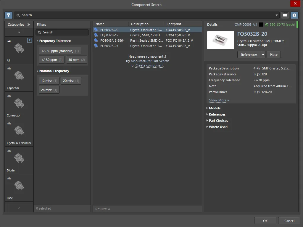
選択された追加のBOMアイテムは、右クリックの操作サブメニューを介していつでも変更できます。
管理されたコンポーネントまたはカスタムアイテムのインスタンスを追加する
管理コンポーネントまたはカスタムアイテムを追加した後、それを右クリックしてOperations » Add Instances ofコマンドを選択し、Add to BOM Components ダイアログにアクセスします。このダイアログを使用して、BOMにコンポーネントのインスタンス数を定義します。
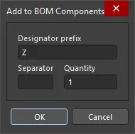
Designator prefix、オプションのSeparator(X-1やX:1のような結果を得るために定義できます)および必要なコンポーネントのQuantityを指定します(この値は指定子の範囲を定義し、ActiveBOMのQuantity列にも表示されます)。説明など、他のパラメータはBOMアイテムグリッドで直接編集できます。
管理されたコンポーネントまたはカスタムアイテムの変更/削除
指定子を編集するか、管理されたコンポーネントまたはカスタムアイテムのインスタンスを削除するには、それを右クリックしてOperations » Edit itemコマンドを選択します。Change / Removeダイアログが開きます。
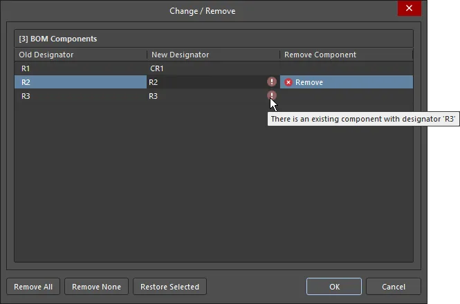
変更/削除ダイアログのオプションとコントロール
-
BOM Components - ダイアログのグリッド領域には、新しいアイテムの各インスタンスがリストされています。デザインネータのプレフィックスまたは値を編集するには、適切なNew Designatorセルをクリックして必要に応じて編集します。
-
Remove All - このボタンをクリックすると、ダイアログにリストされている追加のBOMアイテムのすべてのインスタンスが選択され、削除されるようにマークされます。ダイアログのOKボタンをクリックすると、削除マークが付けられたすべてのアイテムがActiveBOMのBOMアイテムグリッドから削除されます。新しいアイテムのインスタンスがなくなるため、そのアイテムも削除されます。この操作は元に戻すことができません。
-
Remove None - このボタンをクリックすると、すべての削除マークがクリアされます。
-
Remove Selected - 削除されることがマークされていないインスタンスが選択された場合、3番目のボタンを使用して、現在選択されているインスタンスに削除マークを設定できます。
-
Restore Selected - 現在削除のためにマークされているインスタンスが選択された場合、3番目のボタンを使用して、現在選択されているインスタンスから削除マークをクリアできます。
データソース
ActiveBOMで利用可能なデフォルトのデータソースには、回路図コンポーネントのパラメーター(  )、ワークスペースコンテンツのワークスペースコンポーネントのパラメーター(
  )、およびActiveBOMによって提供されるデータ(
  )があります。これらのソースから、ActiveBOMは主要なプロジェクトBOMアイテムグリッドを生成します。データソースは有効にされ、その表示はActiveBOMのColumnsタブのPropertiesパネルで制御されます。
関連するSourcesボタン(列リストの上)を有効にすることで、BOMには以下の追加データソースから取得した情報も含めることができます:
 PCB - 利用可能なColumnsに、各コンポーネントのPCBの位置/回転/基板の面のデータを含めるにはこれを有効にします。プロジェクトに複数のPCBドキュメントが含まれている場合、必要なPCBを選択するために
 ![]() Choose PCB to Useダイアログが開きます。
Choose PCB to Useダイアログが開きます。
 Database - 外部データベース(*.DbLib、*.SVNDbLib、または*.DbLink 経由)から追加のコンポーネントパラメータを読み込むために使用します。
 Altium Cloud Services - これを有効にすると、Altium Parts Provider によって識別され、サプライチェーンソリューションを示しているBOMアイテムの追加のコンポーネントデータにアクセスできます。
 Document Parameters - PCBプロジェクト内のすべての回路図ドキュメントから検出されたパラメータを、利用可能なColumnsに含めるためにこれを有効にします。

各パラメータのソースは、列のリストにあるアイコンによって示されます。
-
カラムリストの上にあるボタンを使って、データソースを有効/無効にできます。ソースが無効になると、そのソースのすべてのデータがグリッドから削除されます。
-
カラムリストの下にあるチェックボックスは、カラムリストの便利なフィルターです。これらを使用して、グリッドからデータを削除することなく、カラムリストにデータソースを追加/削除できます。
Altium Parts Providerを使用するだけでなく、ODBC接続を介して既存の会社データベースに接続することも可能です。これは、Altium DesignerでCustom Parts Provider Synchronization機能を有効にすることによって達成されます(Custom Data SynchronizationオプションをConfigure Platformページ(Importers\Exportersの下)で選択)し、Data Management - Parts Providersページの設定ダイアログでプロバイダとして有効にします。この機能により、会社のデータベースがワークスペースパーツプロバイダとして振る舞うことができます。
行番号列
組み立て図面が含まれるPCB設計や、設計エンジニア、コストエンジニア、購買専門家間でのBOMデータ交換において、BOM行番号(BOMアイテム位置番号)は、BOMの各行を個別に区別するために使用される簡単な方法です。これにより、設計内の対応するコールアウト、コンポーネント、および描写を明確に識別または見つけることができます。
プロジェクトBOMデータソースとして、ActiveBOMはプロジェクトBOMのユーザー定義行番号をサポートしており、手動および自動の行番号(BOMアイテム位置番号)管理機能を備えています。
-
プロジェクトBOMアイテムの位置番号を自動的に設定するには(基本ビューで)、Set Line #  ボタンをクリックします。行番号は、アイテム詳細グループの列にあるLine #列に表示されます。ボタンの右側にあるドロップダウンアイコンをクリックして、開始値と増分値を定義できるLine # Optionsダイアログを開きます。
-
行番号を手動で変更するには、基本ビューモードに切り替えてから、行番号列の必要なセルを選択し:
-
キーボードのDeleteを押してセルの内容をクリアし、その後
-
新しい値を手動で入力するか、または
-
Windowsクリップボードから値の範囲を貼り付けます。
-
カスタム追加された番号から番号を付け直すか、番号付けを続けるには、必要なアイテムの行番号セルをクリックし、その後Set Line #  ボタンをクリックします。Line Numberingダイアログが開き、番号付けを続けるかすべてを再番号付けするを選択できます。Line # Optionsダイアログで最後に定義された基本値と増分値が、必要に応じて追加される番号を計算するために使用されます。必要に応じて、開始番号を定義するために選択された行番号セルにシード値を入力できます。
連番のバリエーションの行番号ダイアログは、ActiveBOMドキュメント(*BomDoc)の一部の行番号が既に定義されている場合に開きます。
すべてを再番号のバリエーションの行番号ダイアログは、ActiveBOMドキュメント(*BomDoc)のすべての行番号が既に定義されている場合に開きます。
行番号管理機能は、ベースビューモードでのみ利用可能です。
BOMアイテムグリッドの表示設定と保存
どのような優れたスプレッドシートアプリケーションと同様に、BOMアイテムグリッドはあなたの要件に合わせて設定することができます。従来の列の順序変更やソート機能だけでなく、現在の設定をBOMセットとして保存することもできます。
BOMセットの操作
BOMアイテムグリッドの設定は何個でも保存できます - これらはそれぞれBOMセットと呼ばれます。グリッドを要件に合わせて設定した後、ActiveBOMのPropertiesパネルのBOM Sets領域にあるAddボタンをクリックして、リストにBOMセットを追加します。
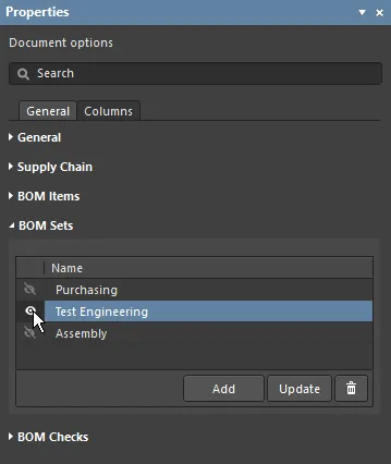
目のアイコンをクリックしてBOMセットを有効にします。
BOMセットは、ActiveBOMのプロパティパネルで設定されます。
コンポーネントの交換
BomDocがチェックされ、部品の注文準備が整っているときにコンポーネントに問題があることが特定されることは珍しくありません。例えば、設計者がコンポーネントの選択を最終決定するのを忘れていたり、コンポーネントがEOL(製造終了)になっており、設計者が代替品の価格や入手可能性を探りたい場合があります。以前は、この問題を解決する唯一の方法は、回路図に戻ってコンポーネントを編集し、適切な部品を選択してから、BomDocを更新することでした。
BomDoc内のコンポーネントを変更し、その変更をエンジニアリング変更命令を通じて回路図に反映させることもできます。選択したコンポーネントを右クリックし、Operations » Change <ComponentName>コマンドを選択します。Replace Componentダイアログが開き、置換するコンポーネントを検索できます。

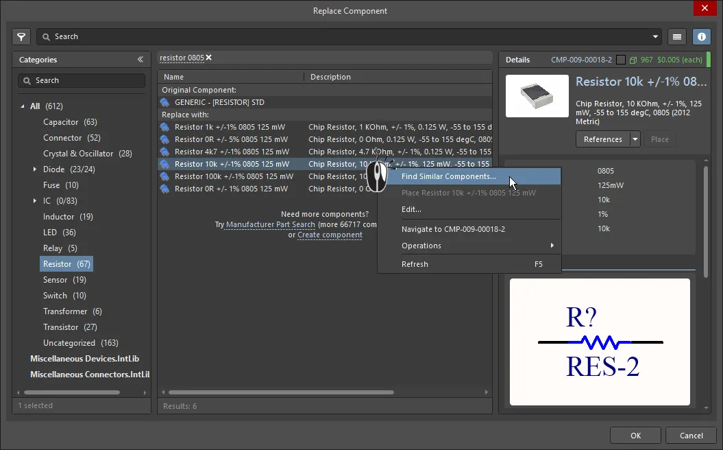
Replace Component のOKボタンをクリックすると、Engineering Change Order ダイアログが開き、BomDocとの同期に必要な変更の詳細が表示されます。
-
「コンポーネントの置き換え」機能は、現在接続されているワークスペースで新しいコンポーネントを検索します。検索によって適切なコンポーネントが返されない場合、ダイアログにはManufacturer Part Searchパネルを開くリンクが表示されます。ここで右クリックして、自分のワークスペースにコンポーネントをAcquireする(Create New ComponentダイアログとComponent Editorを介して)か、またはコンポーネントをzipアーカイブの統合ライブラリパッケージとしてローカルにDownloadすることができます。これらのコマンドは、メーカーパーツ検索パネルで選択した部品にAltium Designerモデルが含まれている場合にのみ利用可能です(  アイコンを探してください)。
-
Replace Componentダイアログの検索、カテゴリ、フィルタ機能の代わりに、結果を右クリックしてFind Similar Componentsダイアログにアクセスすることもできます。このダイアログの強力な点は、右クリックしたコンポーネントの値を取り、それに基づいて、共通の特性やパラメータを持つ複数のコンポーネントを、値の範囲にわたって迅速に見つけることができることです(画像を表示![]() )。
)。
-
コンポーネントの変更がボード設計にも影響を与える場合は、回路図からPCBを更新する必要があります。
► ECOの適用について もっと学ぶ
バリアントを使用する
ActiveBOMは、デザインバリアントを含むPCBプロジェクトをサポートしています。デザインバリアント機能により、単一の基本PCBデザインを作成し、それを異なる方法で搭載(ロード)することができます。組み立てられたボードの異なる搭載は、デザインバリアントと呼ばれます。
デザインバリアントの使用方法:

ActiveBOMは以下の方法でバリアントをサポートします:
-
BaseビューモードまたはFlatビューモードで特定のバリアントのBOMを表示
-
BOMアイテムリストにNot Fittedアイテムを含めるオプション
-
Consolidatedビューモードで、すべてのバリアントで使用される部品の統合リストを表示
-
基本コンポーネントと変更されたコンポーネントの両方に対して手動ソリューションを定義
Baseビューモードでのバリアント
選択されたバリアントについて、これらの部品をBOMアイテムグリッドに含めるために、PropertiesパネルでShow Not Fittedオプションを有効にします。このオプションが有効になると、アイテム詳細にFitted列が自動的に表示されます。
基本ビューモードでは、Fitted列にはFittedまたはNot Fittedが表示されます。部品が変更された場合(このバリアントで代替部品が選択された場合)、そのBOMアイテムの代替部品の詳細が自動的に表示されます。

現在のバリアントがActiveBOMステータスラインに表示されていることに注意してください。
統合ビューモードでのバリアント
統合ビューモードは、すべてのバリアントで使用されるすべてのコンポーネントを表示します。統合ビューには以下の機能があります:
-
構成部品が可変の場合、使用される代替構成部品ごとに BOM 品目が存在し、これらの各 BOM 品目には同じ指定子があります。たとえば、下の画像では、BGAバリアントがTSOPバリアントとは異なる色のLEDを使用しているため、コンポーネントDS1とDS2はそれぞれ2回リストされています。コンポーネント R1 が 3 回表示されるのは、BGA と TSOP の両方のバリアントが基本設計の元の抵抗とは異なる抵抗を使用しているためです。
-
統合表示モードでは、Show Not Fittedオプションが有効な場合、Fitted列にはFittedまたはVariedと表示されます。統合ビューには、すべてのバリアントで使用されるすべてのコンポーネントが表示されるため、表示されるすべてのコンポーネントはベースまたはバリアントのいずれかに適合されます。
-
各バリアントには、<VariantName> - Qty列 (このバリアントで使用されるこのコンポーネントの数を示す) と <VariantName> - Price列 (単価に数量列の値を掛けた値) があります。
-
一部のデザイナーは、ベース デザインとバリアントからビルド ドキュメントを作成するため、ベース デザインのビルドで使用されるこのコンポーネントのインスタンス数を反映するQuantity列もあります。ベース デザインからビルド ドキュメントを生成しない場合は、この列を非表示にします。
-
統合ビュー モードのグリッドは、次に示すように、色を使用して、値が基本設計のセルの値と異なるセルを示します。

セル内の色は、このセルの値がベースデザインのそのセルの値と異なることを示しています。
バリアントについての詳細は、デザインバリアントのページを参照してください。
BomDoc、回路図、PCB間での作業
BomDoc、回路図、PCB設計の間で作業を助けるために利用できる機能が2つあります:クロスセレクトとクロスプローブです。これらの機能の動作は、PreferencesダイアログのSystem - Navigationページで設定されます。
これらの機能はどちらも、他のドキュメントで同じコンポーネントを見つけるために使用できます。クロスセレクトとクロスプローブの違いは、クロスセレクトモードがターゲットドキュメントでコンポーネントを選択するだけで、そのドキュメントを積極的に表示しないのに対し、クロスプローブはターゲットドキュメントを積極的に表示し、さらにターゲットドキュメントのエディタをアクティブなエディタに切り替えることもできることです。
BomDocから回路図やPCBにクロスセレクトまたはクロスプローブすることができますが、回路図やPCBからBomDocにクロスセレクトまたはクロスプローブすることはできません。
クロスセレクトモード
クロスセレクトモードを使用するには、それを使用したい各エディタで有効にする必要があります。Tools » Cross Select Modeコマンド(Shift+Ctrl+X)を選択します。クロスセレクトモードが有効になると、メニューアイコンがアウトラインでハイライト表示されます  。
。
クロスセレクトモードを使用するには、対象のドキュメントを開いている必要があります。BomDocのBOMアイテムリストでコンポーネントを選択すると、そのコンポーネントは対象の回路図とPCBドキュメントで選択され、中央に配置されます(ZoomingがCross Select Modeオプションで有効になっている場合、PreferencesダイアログのSystem - Navigationページで)。ただし、対象のドキュメントがアクティブなドキュメントとして表示されることはありません。
BomDocがベースビューモードにある場合、下の画像に示されているように、その部品のすべてのインスタンスが回路図とPCB上で選択されます。
Cross Select Modeの表示動作は、PreferencesダイアログのSystem - NavigationページにあるCross Select Modeオプションを使用して制御されます。
対象のドキュメントはアクティブなドキュメントにはなりません。そのため、ソースドキュメントとターゲットドキュメントを並べて開いておくことをお勧めします。
回路図(またはPCB)からBomDocへのクロスセレクションもサポートされています。

BOMアイテムリストで選択されたコンポーネントを回路図やPCB上で探して選択するためにCross Select機能を使用します。
クロスプロービング
Cross Selectは単にモードであり、有効にすると、BOMアイテムリストでクリックするたびに結果が表示されますが、クロスプローブは意図的なアクションです。
メインメニューからTools » Cross Probeコマンドを選択するか、BOMアイテムを右クリックしてコンテキストメニューからCross Probe を選択すると、そのコンポーネントを回路図上でクロスプローブできます。ボードファイルが開いている場合は、PCBコンポーネントもクロスプローブされます。 クロスプローブの重要な機能の一つは、対象ドキュメントのエディタに切り替える能力です。Cross Probe コマンドを選択する際にCtrlキーを押し続けると、エディタを切り替えてクロスプローブします。
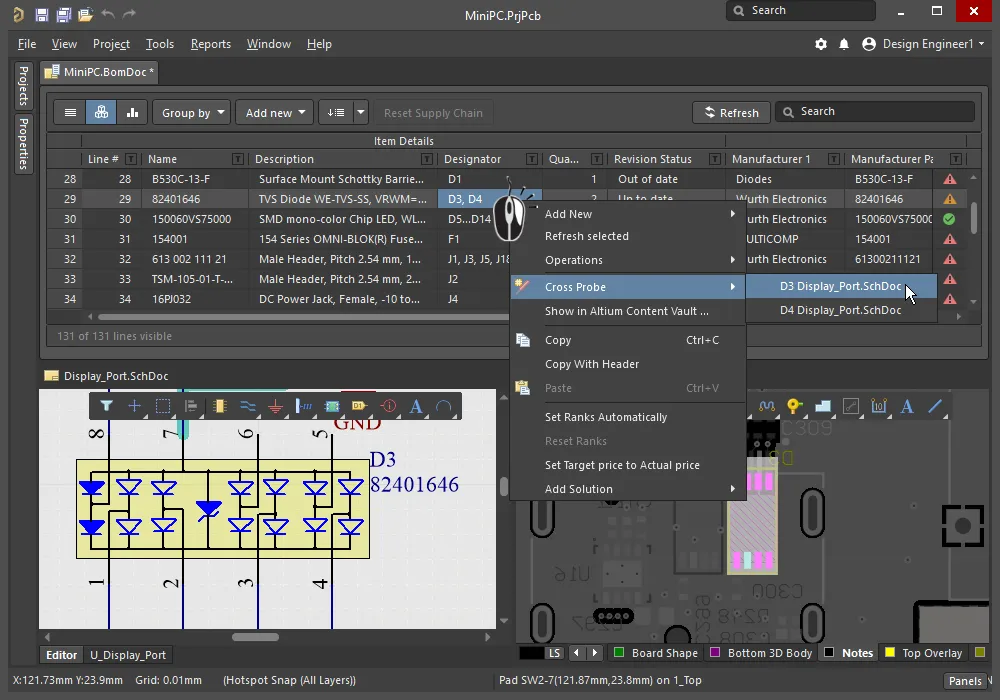
右クリックしてクロスプローブコマンドにアクセスします。そのBOMアイテムに存在する各コンポーネントのデザイネーターに対するエントリーがあります。
クロスプロービング中は、BomDoc(ソース)と回路図(ターゲット)のドキュメントをメインデザインウィンドウを分割するか、新しいウィンドウで回路図を開くことにより、並べて表示する方が効率的です。これらのコマンドは、ドキュメントタブの右クリックメニューで利用可能です。
プロパティパネル
アクティブなドキュメントがBOMドキュメント(*.BomDoc)の場合、プロパティパネルにはDocument Optionsが表示されます。
以下の折りたたみ可能なセクションには、利用可能なオプションとコントロールに関する情報が含まれています:
一般
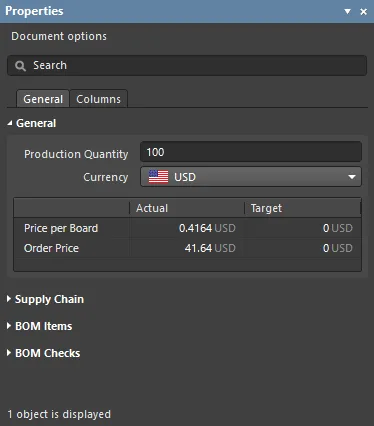
-
Production Quantity – 製造されるボードの数です。このフィールドを定義することは、サプライチェーン検索時にサプライヤーからの部品の可用性を確認するために使用されるため、重要です。
-
Currency – 部品価格を表示するための好みの通貨です。通貨変換のための為替レートは、Altiumアカウントにサインインしている場合、毎日更新されます。Altiumから切断された場合(PreferencesダイアログのSystem – Account Managementページで)、これらの更新されたレートへのアクセスが失われます。この状況では、BOMレポートダイアログでキャッシュされたデータを使用するオプションがあります。
-
Price Per Board – サプライヤーベースのデータから導き出され、以下に説明されているSupplier Subtotals per Boardの合計です。なお、Price Per Boardは、最小注文数量(MOQ)を考慮していません。
-
Order Price – Supplier Subtotals.の合計です。Order PriceはMOQを考慮しており、これがサプライヤーに支払われる金額です。
1枚あたりの価格と注文価格を導き出すために使用される以下のサプライヤーベースのデータは、Columns領域の各希望項目のチェックボックスを有効にすることで、部品表に含めることができます:
-
Manufacturer n - 製造元の名前。
-
Manufacturer Lifecycle n - 利用可能な場合、製造元のライフサイクルステータス。
-
Manufacturer Part Number n - 製造元の部品番号。
-
Supplier n - サプライヤーの名前。
-
Supplier Currency n – 価格データに使用される選択された通貨のアルファベットコード。
-
Supplier Order Qty n – (アイテムQuantity * Production Qty)またはMinimum Order Qty(MOQ)のいずれか高い値。
-
Supplier Part Number n – サプライヤーアイテムの部品番号。
-
Supplier Stock n – サプライヤーが在庫しているアイテムの単位数。
-
Supplier Subtotal per Board n – Supplier Unit PriceにアイテムQuantityを掛けたもので、そのアイテムの小計です。この値はMOQを考慮していません。
-
Supplier Subtotal n – Supplier Unit PriceにSupplier Order Quantityを掛けたもので、MOQを考慮したそのアイテムの小計です。
-
Supplier Unit Price n – サプライヤーアイテムの単位あたりのコスト(MOQを考慮せず)。
各BOMアイテムに対して目標価格が定義されている場合、Target列がこれらを反映します。各BOMアイテムに目標価格を入力するには、パネルのColumnsタブでTargetPrice列を有効にし、アイテムグリッドに各アイテムの価格を入力します。
サプライチェーン
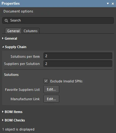
サプライチェーン情報はActiveBOMインターフェースの下部に表示され、左側にメーカーのコンポーネントが、その右側に一つ以上の色付きのサプライヤータイルが表示されます。この領域は、BOMアイテムに有効なサプライチェーン情報を特定できる場合にデータを表示します。これらのメーカー&サプライヤー詳細の各行はソリューションとして参照されます。メーカーの詳細はMPN(メーカー部品番号)に、サプライヤーの詳細はSPN(サプライヤー部品番号)に略されます。
BOM項目
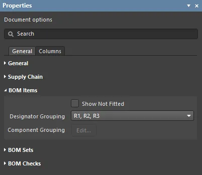
この領域は、BOM項目グリッド内でBOM項目をどのようにグループ化するかを設定するために使用されます。
-
Items
-
Show not Fitted – PCBプロジェクトにバリアントが含まれており、選択したバリアントにNot Fittedと設定された部品がある場合、BOM項目グリッドに取り付けられていない項目を表示するためにこれを有効にします。
-
Designator Grouping – 基本および統合ビューモードは、BOM項目グリッドの単一行に共通部品を表示します。このオプションを使用して、行が複数の部品を表示する場合に指定子が個別に表示されるか範囲で表示されるかを設定します。
-
Component Grouping – EditボタンをクリックするとComponent Groupingダイアログが開きます。BaseビューまたはConsolidatedビューでは、ActiveBOMは同じItemID(ワークスペースライブラリ)またはLibRef(ファイルベースまたはデータベースライブラリ)を共有するコンポーネントを同じものとして識別します。ダイアログ内のパラメータを有効にして、コンポーネントのグループ化方法をさらに洗練させます。プロジェクトに管理されたコンポーネントのみが含まれている場合、管理されたコンポーネントは常にItemIDでグループ化されるため、Editボタンにアクセスできなくなります。

追加パラメータを追加する場合、Addボタンをクリックした後、リストにSelect parameterというテキストが表示されます。テキストをダブルクリックして、現在のすべてのBOM項目で検出されたすべてのパラメータのリストを表示し、リストから必要なパラメータを選択します。いつでもDefaultsボタンをクリックすることで、デフォルトのパラメータ(上の画像に示されているように)に戻ることができます。
BOMセット
BOMセットは、BOMアイテムグリッドのレイアウトと構成をキャプチャして、名前付きセットとして保存する方法を提供します。任意の数のBOMセットを定義できます。
-
Current BOM Set - 目のアイコンをクリックして、そのBOMセットをBOMアイテムグリッドに適用します。
-
Add - 列の表示、順序、幅を設定し、**追加**をクリックしてその構成をBOMセットとしてキャプチャします。BOMセット名を編集するには、一度選択してから、もう一度クリックして文字列を編集します。
-
Update - BOMアイテムグリッドの構成が変更された場合、**更新**をクリックしてこの構成を再保存します。
-
Delete - 現在選択されているBOMセットを削除するには、  をクリックします。