Parent page: Managing Design Changes between the Schematic & PCB
Classes are provided to enable various commands to operate on subsets of object types, for example, a group of components or a group of nets. An object can belong to more than one class.
Classes can be created for:
- nets
- components
- layers
- pads
- from-tos
- differential pairs
- design channels
- polygons
- xSignals
Also, Structure Classes can be created. A Structure Class is a special type of class that can hold, as its members, any type of class.
Generation and Synchronization of Classes from the Schematic
When transferring the design from the schematic to PCB, Altium Designer provides support for generation of component and net classes. There are two types of classes that can be generated from the schematic and synchronized to the PCB:
- Automatic classes - derived from the buses/harness, components, or sheet contents; and
- User-defined classes - derived from design directives placed by the designer.
The generation of these are configured in the Class Generation tab of the Options for Project dialog (the synchronization is controlled by options in the Comparator tab).
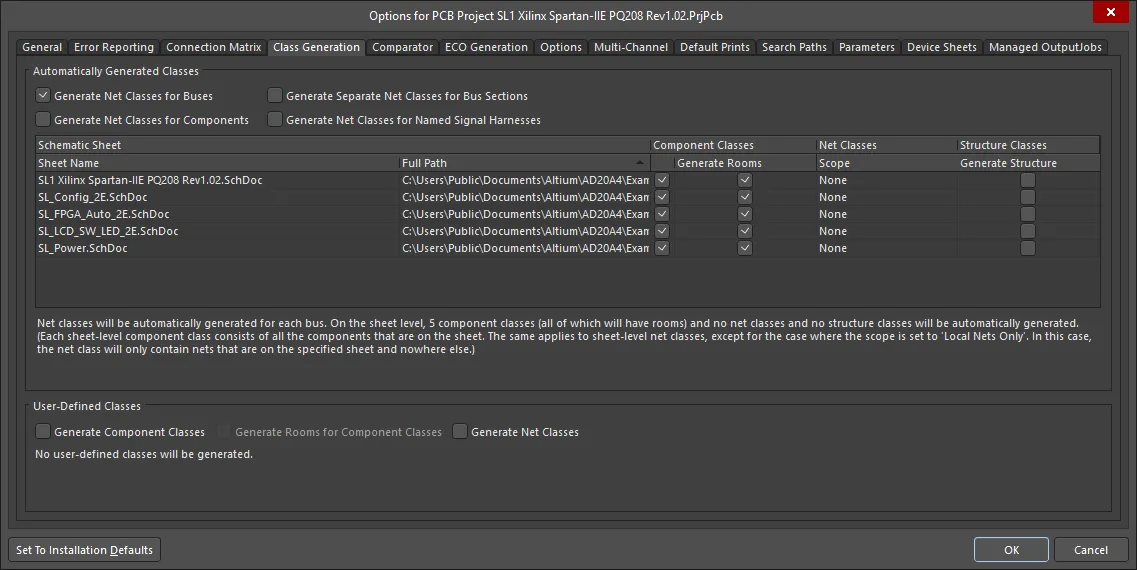
Use the options in the Class Generation tab to configure the automatically generated classes you require, and if you want to create user-defined classes during design synchronization.
Automatically Generated Net Classes
Net classes can be automatically generated for the following groups of nets:
-
Generate Net Classes for Buses - check this option to automatically generate a net class for each bus in the design. The members of a class will be the individual constituent nets of the bus (from which that class was generated).
A generated net class will be named using the name of the bus.
-
Generate Net Classes for Components - check this option to automatically generate a net class for each component in the design. The members of a class will be the associated nets to which the pins of the component (from which that class was generated) are connected.
A generated net class will be named using the designator of the component in the format <ComponentDesignator>_Nets.
- Generate Separate Net Classes for Bus Sections - check this option to automatically generate a separate net class for each bus section. A bus section is created by specifying a bus which is actually a section of a larger bus, for example
D[15..8], from the bus D[15..0].
-
Generate Net Classes for Named Signal Harnesses - enable this option to automatically generate a net class for each named signal harness in the design. The members of a class will be the nets associated to the signals gathered by the named signal harness (from which the class was generated).
A named signal harness is one that has a net label attached to it. A generated net class will be named using the name of the net label attached to the signal harness.
- Sheet-Level Class Generation Grid - this region allows you to control the automatic generation of component and/or net classes at the individual schematic sheet level. All source schematic sheets for the project are listed with the following information presented for each:
- Sheet Name - the name of the schematic document.
- Full Path - the absolute path to the folder in which the document resides.
- Component Classes - check this option to have a component class generated for the sheet.
- Net Classes Scope - use this field to determine whether to have a net class generated for the sheet and, if so, the scope of generation. The field's drop-down provides the following choices:
- None - do not generate a net class for this sheet.
- Local Nets Only - generate a net class for this sheet but only containing member nets that are local to the sheet.
- All Nets - generate a net class for this sheet that contains all member nets associated with the sheet (local and those that go elsewhere).
- Structure Classes Generate Structure - check this option to have a structure class generated for the sheet.
Enable/disable component class generation or set the scope for net class generation as a whole using commands available from the right-click context menu for a column. Multiple sheet entries can be selected using standard multi-select techniques (Ctrl+click, Shift+click, click&drag).
For components and/or nets on the top sheet, the respective component and/or net class will be named using the schematic document name. For components and/or nets on child sheets, the respective component and/or net classes will be named using the sheet symbol designators.
The text at the bottom of this region dynamically changes based on the choices made and provides a summary of which classes will be automatically generated.
Automatically Generated Component Classes
It is common for the schematic project to be structured over multiple sheets, with each sheet representing a logical block of the overall design. Supporting this, you can automatically generate a component class that contains all of the components on that sheet, for each of the schematic sheets in the project, by enabling the appropriate Component Class checkbox. The PCB component class will have the same name as the Designator of the sheet symbol that references that schematic sheet. A component class will not be created if the sheet does not contain any components.
Automatically Generated Rooms
A room is a polygonal-shaped object that is an aid to component placement, these are created automatically for each schematic sheet that has the Generate Rooms checkbox enabled.
Automatically Generated Structure Classes
A structure class can include net classes, component classes, and lower-hierarchical-level structure classes, as its members. A structure class is created for each sheet that the option is enabled for, and will include the sheet-level component and net classes, if those options are enabled for that sheet. Edit the Structure Class in the PCB editor to add other net / component / structure classes. Use the Structure mode of the PCB panel to locate the components and nets in that structure class.
Creating User-Defined Classes
You can also create user-defined component classes and net classes, by attaching a parameter to the relevant component or net. PCB component and net classes will then be created if the appropriate User-Defined Classes checkboxes are enabled in the Class Generation tab of the Options for Project dialog.
User-Defined Net Class
Object page: Parameter Set
To add a net (or the nets in a bus or signal harness) to a PCB net class, you need to attach a parameter to that net/ bus / harness. You do that by placing a Parameter Set object with its end touching the net / bus / harness, as shown in the image below (Place » Directives » Parameter Set command).
In the Classes section of the panel, enter the name of the net class, as shown in the image below.
Multiple Parameter Set objects can be placed in different locations on the schematic, to add multiple individual nets to the same PCB net class.
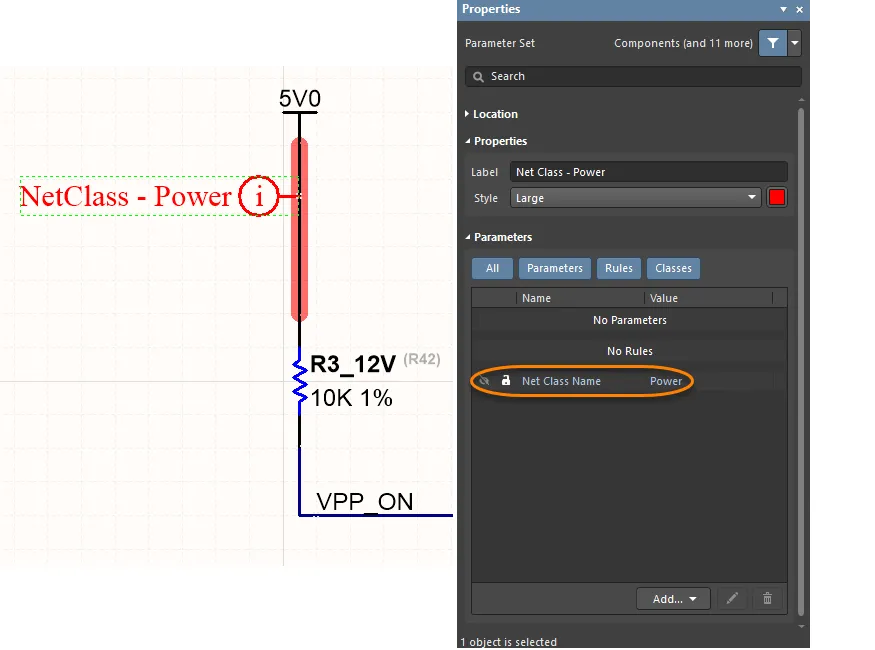
To add a net to a PCB net class, attach a Parameter Set object to the schematic net, then add a Class definition to the Parameter Set object.
User-Defined Component Class
In the schematic, you can specify that a component be added to a PCB component class when the schematic is synchronized with the PCB.
To do that, you add a parameter to the component, with the parameter Name string set to ClassName, and the parameter Value string set to the required.
Using a Blanket to Apply a Directive to Multiple Nets
Object page: Blanket
You can also add multiple nets to a PCB net class by placing a Blanket directive that covers all of those nets. The function of a Blanket is to allow you to apply a directive to all of the nets under the blanket (either identified by a net identifier, such as a Net Label or Power Port that is under the blanket, or a net that has an end vertex contained within the Blanket).
Instead of placing the Parameter Set directive so that it touches a wire, you place it so that it touches the edge of the blanket, as shown in the image below. Note that it is the value of the Parameter within the Parameter Set object that defines the PCB net class name, not the display name of the Parameter Set object. In the example image below, the Parameter Set is also used to define a routing width design rule.
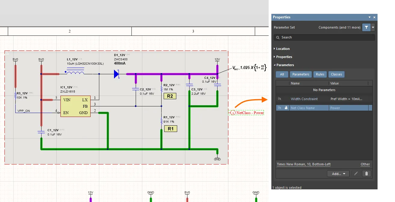
Using a Blanket directive to bundle all the nets under it, into a PCB net class called Power. Note that the Parameter Set object name is not used for naming, it is a visual reference only.
Working with Classes on a PCB
Object classes for the active PCB document can be browsed and managed from two key locations:
- The Classes region of the relevant mode of the PCB panel. From here you can add a new user-defined class (right-click, then choose Add Class), or edit the membership of an existing user-defined class (double-click or right-click, then choose Properties). The name of the class and its members are defined in the corresponding Edit Class dialog.
You can only add and edit user-defined classes. The default system classes cannot be edited.
 Example access of properties for an existing user-defined component class, from the PCB panel (configured in its Components mode).
Options and Controls of the Edit Class Dialog
- The Object Class Explorer dialog, accessed by choosing the Classes command on the PCB Editor's main Design menu.
 The Object Class Explorer dialog
Options and Controls of the Object Class Explorer Dialog
The dialog includes a static pane on the left and a main editing region on the right that changes in context with the selection on the left.
Left-Hand Pane
In the folder-tree pane on the left side of the dialog, each of the supported object class types are listed under the Object Classes folder. The following class types are supported:
- Net Classes
- Component Classes
- Layer Classes
- Pad Classes
- From To Classes
- Differential Pair Classes
- Design Channel Classes
- Polygon Classes
- Structure Classes
- xSignal Classes
Click on the root folder to access a summary listing in the main editing region of the dialog of all specific classes that have been defined across all object class types (shown in the back image).
Click on a child object class type folder to access a summary listing of all specific classes that have been defined for that type. The following default classes are created across the various class types for a new PCB document:
- Net Classes - <All Nets>.
- Component Classes - <All Components>, <Bottom Side Components>, <Inside Board Components>, <Outside Board Components>, <Top Side Components>.
- Layer Classes - <All Layers>, <Component Layers>, <Electrical Layers>, <Signal Layers>.
- Pad Classes - <All Pads>.
- From To Classes - <All From-Tos>.
- Differential Pair Classes - <All Differential Pairs>.
- Polygon Classes - <All Polygons>.
- xSignal Classes - <All xSignals>.
Default (system classes) are distinguished by their names being enclosed in <>. These classes cannot be renamed and they cannot be deleted.
Whenever an applicable design object is created/placed in the design, it is added to the default <All> class for the respective class type.
Click on the entry for a specific class in the folder-tree pane (or double-click on its entry in a summary list) to access controls for managing the object membership of that class.
Right-Click Menu
The following commands are available from the right-click context menu for the pane:
- Add Class - use to add a new class of the currently selected class type. The class will be added, initially devoid of members, with a default name of New Class.
- Delete Class - use to delete the currently selected class.
- Rename Class - use to rename the currently selected class.
Remember that you cannot rename or delete the default (system) classes.
You also can rename a class by clicking once to select it, then clicking again to enter editing mode.
Main Editing Region
This region of the dialog changes in accordance with what is currently selected in the left-hand pane. It presents two different views:
- Summary Listing - if the root Object Classes folder or any of the child object class type folders are clicked in the left-hand pane, this region presents a summary listing of all defined classes or all classes of the selected class type, respectively. Each class is listed in terms of its Name and Class Type.
- Membership Management - if a specific class is selected in the left-hand pane, this region presents controls for managing its member objects.
- Non-Members - this region lists all primitives of the applicable type that are currently not members of the class. Use the field above the list to quickly filter the contents of the list.
- Members - this region lists all primitives of the applicable type that are currently members of the class. Use the field above the list to quickly filter the contents of the list.
As you type within one of the fields above a list, the list is filtered to only show strings that match the string. You can use the ? (any single character) and * (any character) wildcards in the mask string. For example, use "*" to display all primitives or "D?" to display all primitives that start with the letter D.
A design object of a particular type can belong to (be a member of) any number of classes defined for that object type.
- Component Class Generator - this button is available only when editing a component class. Click it to access the Component Class Generator dialog, which can be used to quickly generate the membership for the component class based on defined search criteria.
- Membership Management Buttons - the region provides the following buttons to cater for moving primitives quickly between the two lists:
-
 Add All - click to quickly transfer all primitives from the Non-Members list to the Members list.
-
 Add Selected (in dialog) - click to quickly transfer the primitives currently selected in the Non-Members list to the Members list.
-
 Remove Selected (in dialog) - click to quickly transfer those primitives currently selected in the Members list to the Non-Members list.
-
 Remove All - click this button to quickly transfer all primitives from the Members list to the Non-Members list.
-
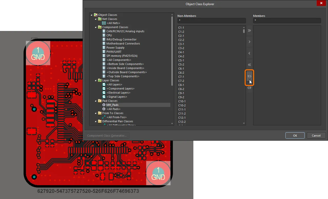
 Add Selected (in workspace) - click this button to quickly transfer those primitives currently selected in the design workspace from the Non-Members list to the Members list.
-
 Remove Selected (in workspace) - click this button to quickly transfer those primitives currently selected in the design workspace from the Members list to the Non-Members list.
Click on an existing user-defined class to present its members and modify as required. To add a new user-defined class, right-click within the category of class you want to create and choose Add Class from the context menu. A new class will appear in the list with the default name New Class. Click on the class name to access and define its members. To rename a class, either click on its name, then click again to focus it for editing, or right-click on it and choose Rename Class.
Note that there are transfer buttons for selected objects; often it is easier to select the objects in the design space first, then use these transfer selected buttons to build the class. If you have created a selection beforehand using the Find Similar Objects dialog, PCB panel, list panel, etc., then the button shown in the image below should be available. Pressing this button shifts the selection from the non-members column to the members column.
Component Class Generator
When adding or editing a component class, you have the ability to quickly generate its membership based on defined search criteria. This is performed using the Component Class Generator dialog, accessed by clicking the Class Generator button (at the bottom-left of the Edit Component Class dialog) or the Component Class Generator button (at the bottom-left of the Object Class Explorer dialog). A range of attributes can be used to effectively 'capture' the components that you want to add as class members, including Designator, Comment, and Footprint. At a click of a button, all components matching the search criteria are added to the class.
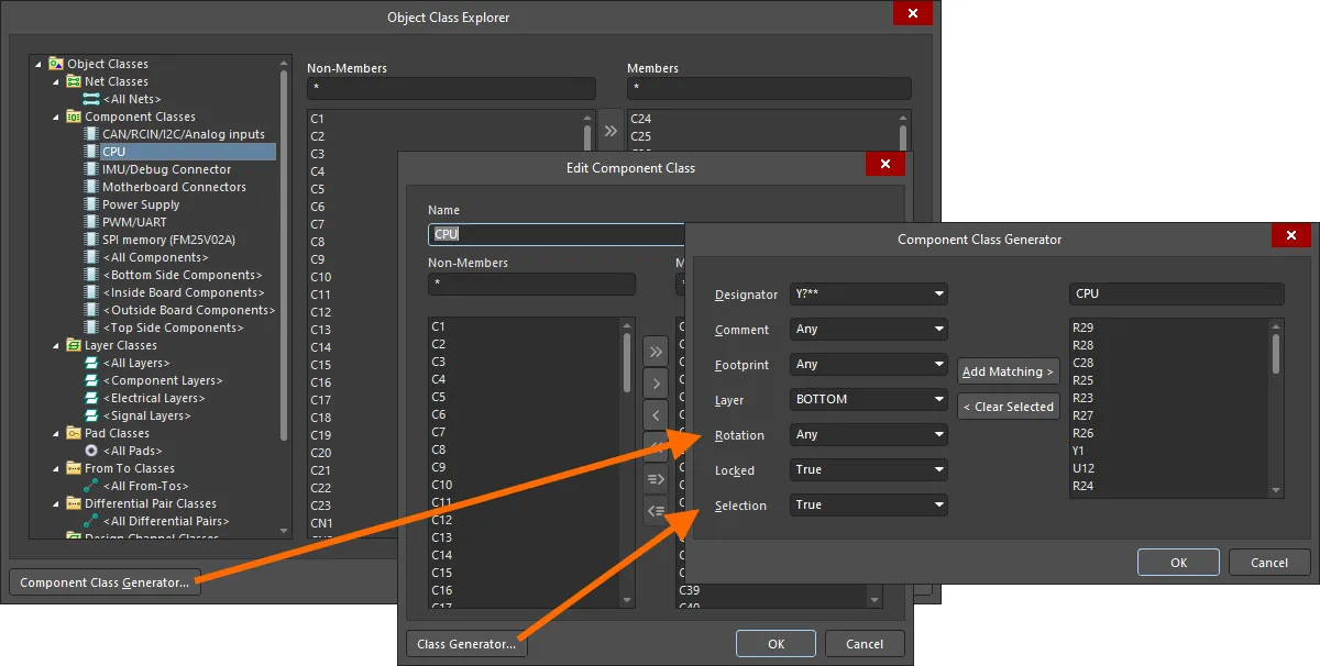
Options and Controls of the Component Class Generator Dialog
- Search/Filter Criteria - the left-hand side of the dialog provides a number of fields that collectively define the search/filter criteria, used to target the components that are to be added as members of the component class. The following criteria can be configured:
- Designator - use this field to search/filter based on component designator. Use the field's drop-down to choose the type of components to target. All unique designator types found in the board design will be listed in the format <DesignatorPrefix>?? (e.g. U**, R**, C**). To include components regardless of designator type, set this field to Any.
- Comment - use this field to search/filter based on the component comment. Use the field's drop-down to choose the component comment to target. All unique component comments found in the board design will be listed. To include components regardless of their comment, set this field to Any.
- Footprint - use this field to search/filter based on the component footprint. Use the field's drop-down to choose the footprint to target. All unique component footprints found in the board design will be listed. To include components regardless of their footprint, set this field to Any.
- Layer - use this field to search/filter based on which side of the board the components reside. Use the field's drop-down to target components on the TOP or BOTTOM. To include components regardless of the layer on which they reside, set this field to Any.
- Rotation - use this field to search/filter based on component rotation. Use the field's drop-down to choose a specific rotation to target. All unique component rotations found in the board design will be listed. To include components regardless of their orientation, set this field to Any.
- Locked - use this field to search/filter based on the component's locked status. Use the field's drop-down to target components that are locked (True) or not locked (False). To include components regardless of their locked status, set this field to Any.
- Selection - use this field to search/filter based on the component's selection status. Use the field's drop-down to target components that are currently selected in the workspace (True) or not selected (False). To include components regardless of their selection status, set this field to Any.
- Class Name - this field, directly above the current member's list for the class, presents the current name of the class. Edit this field as required.
- Class Membership - this region, below the Class Name, lists all components, by designator, that are currently members of the component class.
- Add Matching - click to add all components that match the defined search/filter criteria to the Class Membership region.
- Clear Selected - click to have all components that are currently selected in the Class Membership region removed from the class.
Components can be selected using standard multi-select techniques: Ctrl+click, Shift+click, and Click+drag.
Working with Structure Classes
Altium Designer already provided high-quality, robust support for generation of classes (Component and Net) when transferring the design from the Schematic to PCB. This support is taken to the next level, with the ability to define the generation of a hierarchical structure of classes in the PCB document. Essentially, this enables you to group together, at the sheet-level, classes of components and/or nets into a parent class generated from that sheet, which itself can be a child of the pare nt class above, all the way up to the top-level sheet in your design, which in essence is the source for the top-level generated parent class (or 'super class') – the head of the class structure hierarchy. Each of these generated parent classes is referred to as a Structure Class. Structure Classes not only allow for the reproduction of the schematic document structure within the PCB domain, for advanced navigation, but can also be used in logical queries, for example when scoping design rules, or filtering.
Structure Class Concept
A Structure Class is a special type of class that can hold, as its members, any type of class:
- Net Classes
- Component Classes
- Layer Classes
- Pad Classes
- From To Classes
- Differential Pair Classes
- Design Channel Classes
- Polygon Classes
- Other Structure Classes.
By automatically generating a Structure Class from each schematic sheet in the project – containing components and/or nets – when transferring the design to the PCB, the structure of the project can be faithfully represented on the PCB side.
A tidy means by which to essentially 'compartmentalize' a schematic sheet's-worth of components and nets, the Structure Class object is the driving force behind hierarchical class structuring in the PCB. Using Structure Classes, a hierarchy of any depth can be built. Primarily the structure is defined by the hierarchical nature of the schematic source documents, but you can add, manage and delete Structure Classes directly on the PCB side should you wish.
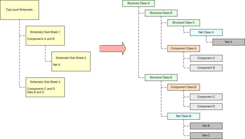
Bringing class hierarchy to the PCB - the concept of Structure Classes allows for a faithful reproduction of the project hierarchy, with each Structure Class essentially representing a single schematic sheet, with generated sub-classes of member components and/or nets thereon.
The Structure Classes reflect the design hierarchy – of the schematic sheets themselves. In terms of component and net classes, membership within a particular Structure Class will of course depend on the options specified when generating Component and Net Classes from the source schematic sheets.
Tailor membership of Structure Classes to suit your needs. Remember that although the project hierarchy can be brought across in an automated fashion, the initial membership will be Component Classes and/or Net Classes and/or other Structure Classes. Use existing Structure Classes, or create new ones within the overall hierarchy, to organize other class types for the PCB document as required.
Automatic Generation of Structure Classes
The automatic generation of Structure Classes from the schematic sheets in a PCB design project is defined on the Class Generation tab of the Options for Project dialog (Project » Project Options). To generate a Structure Class from a source schematic sheet in the project, simply enable its associated Generate option, in the Structure Classes column.

Specify which schematic sheets are to have a Structure Class generated from them when the design is synchronized with the PCB document.
Each automatically generated Structure Class is named using the designator of the Sheet Symbol/Device Sheet Symbol by which the corresponding schematic sub-sheet is referenced. The exception to this is the top-sheet, the corresponding Structure Class of which is named using the filename for that sheet.
Comparator and ECO Generation Support
Synchronization between the source schematic documents and the PCB is made possible through Altium Designer's Comparison engine, with detected differences addressed by performing modifications, implemented through Engineering Change Orders (ECOs). In support of Structure Classes, the Comparator and ECO Generator have been enhanced accordingly.
For detection of differences associated with Structure Classes, a new section has been added to the Comparator tab of the Project Options dialog – Differences Associated with Structure Classes.
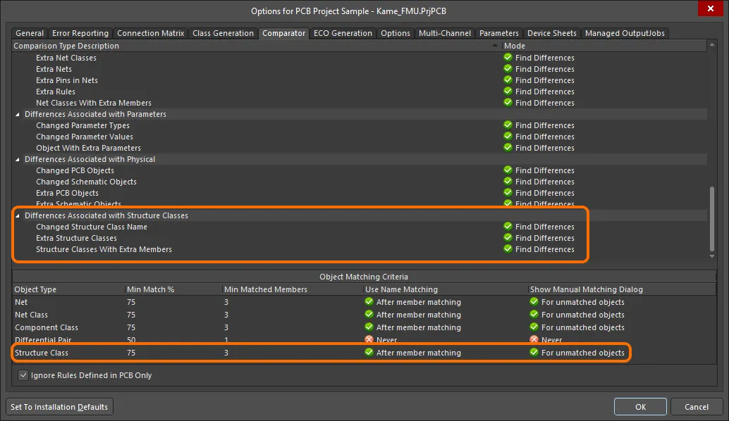
Additional comparison tests for Structure Classes.
Supporting the change orders required to ensure synchronization, a corresponding new section has been added to the ECO Generation tab of the Project Options dialog – Modifications Associated with Structure Classes.

Additional modification types for Structure Classes - used to generate the applicable change orders to maintain synchronization between source schematics and PCB. An example ECO is shown to illustrate addition of Structure Classes to the PCB.
Manual Definition of Structure Classes
As with other types of class in a PCB document, you are able to create and manage Structure Classes in a manual fashion, directly from within the PCB document. This can be done from the PCB panel, while browsing the class structure hierarchy, or from the Object Class Explorer dialog (Design » Classes). Considering the latter here, Structure Classes are defined under the Structure Classes folder, with familiar commands on the right-click menu to add, rename or delete commands as required. For a new or existing Structure Class, define its members as required. These can consist of any of the class types supported for use in the PCB design.
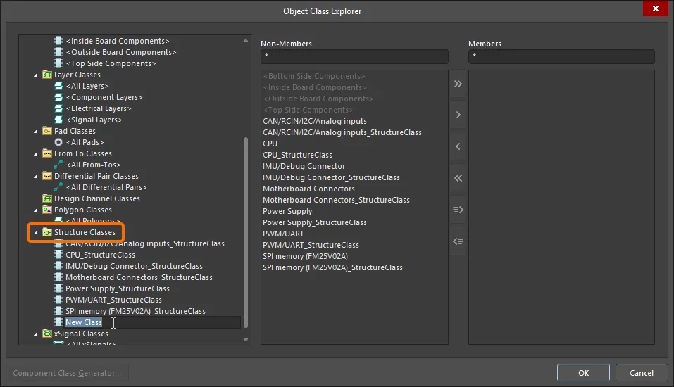
Create and manage your Structure Classes as you would any other type of class, directly in the PCB from the Object Class Explorer dialog.
Browsing the Class Structure Hierarchy
In the PCB panel’s Structure Classes mode, its three main regions change to reflect the following (in order from the top):
- A list of all Structure Classes currently defined for the PCB document; those auto-generated from the schematic sheets as well as those defined in the PCB itself.
- All Classes that are defined members of that selected Structure Class.
- Individual Class Members that constitute each class (components, nets, etc.).

Set the PCB panel's mode to Structure Classes to browse the overall class hierarchy for the PCB document. The display in the main design window will change to reflect the filtering applied as you click on an entry (or entries) in the panel's various regions.
Structure Classes Region
The top region of the panel lists all Structure Classes currently defined for the PCB document. These include those automatically generated from the PCB project's source schematic documents (denoted by the  icon), as well as those defined manually in the PCB document itself (denoted by the
  icon). Clicking on the arrow icon next to a Structure Class will reveal the Structure Class hierarchy descendant from that class. By expanding the top-level Structure Class, you can see the full hierarchy.

Structure Classes for an example PCB
Double-click on a Structure Class entry to access the Edit Structure Class dialog in which you can change the name for the class and redefine its members (any of the class types) as required.
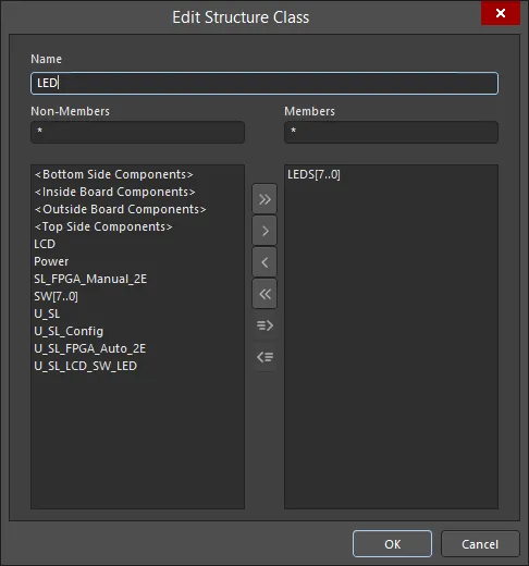
A familiar editing dialog for making changes to a Structure Class as required.
The right-click menu for this region provides the following commands:
- Select All – select all Structure Class entries in the current branch of the hierarchy.
- Clear Filter – clear filtering in the design space.
- Report – generate a report presenting a flat listing of all defined Structure Classes. The report will open for preview in the Report Preview dialog.
- Properties – access the Edit Structure Class dialog for the currently selected (and focused) Structure Class. This command is the same as double-clicking directly on an entry.
- Add Class – add a new Structure Class. Definition (name and membership) is performed from the Edit Structure Class dialog.
- Delete Class – delete the selected Structure Class(es).
Classes Region
The middle region of the panel lists all class members for the currently selected Structure Class(es) in the region above.
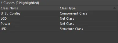
Example class members of the selected Structure Class(es).
Double-click on a class entry to access the associated editing dialog, from where you can change the name for the class and redefine its members as required.
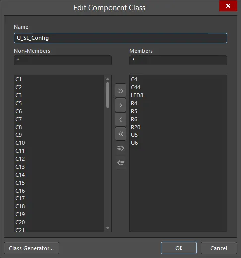
The associated editing dialog for a Component Class entry.
The right-click context menu for this region provides the following commands:
- Select All – select all class entries in the region.
- Clear Filter – clear filtering in the design space.
- Report – generate a report presenting a listing of all classes in the region. The report will open for preview in the Report Preview dialog.
- Properties – access the relevant editing dialog for the currently selected (and focused) class. This command is the same as double-clicking directly on an entry.
Class Members
The bottom region of the panel lists all members of the currently selected class(es) in the region above.

Example members of the selected class(es).
Double-click on a class member entry to access the associated mode of the Properties panel in which you can change the name for the class and redefine its members as required.
The right-click menu for this region provides the following commands:
- Select All – select all class member entries in the region.
- Clear Filter – clear filtering in the design space.
- Report – generate a report presenting a listing of all class members in the region. The report will open for preview in the Report Preview dialog.
- Properties – access the relevant properties/editing dialog for the currently selected (and focused) class member. This command is the same as double-clicking directly on an entry.
- Zoom Selected – this is only available for a primitive object entry. The design space will zoom into that object in the design space, in accordance with the defined Zoom Level. Note that this command has no effect if the Zoom option is enabled as part of the panel's highlighting controls.
Using Structure Classes in Logical Queries
Logical queries are the fundamental driving force when targeting objects in a design. They can be used when scoping design rules to constrain the design in a specific (and required) way, or when filtering objects in the design workspace. The Query Language has been enhanced to cater for the use of the Structure Class when building logical query expressions. The following keyword has been added to the PCB Functions – Membership Checks section:
InStructureClass – checks whether the object class is in the specified Structure Class.
This keyword can also be used when constructing a query with which to scope a design rule. It is supported for use in both the Query Helper dialog and the Query Builder dialog.
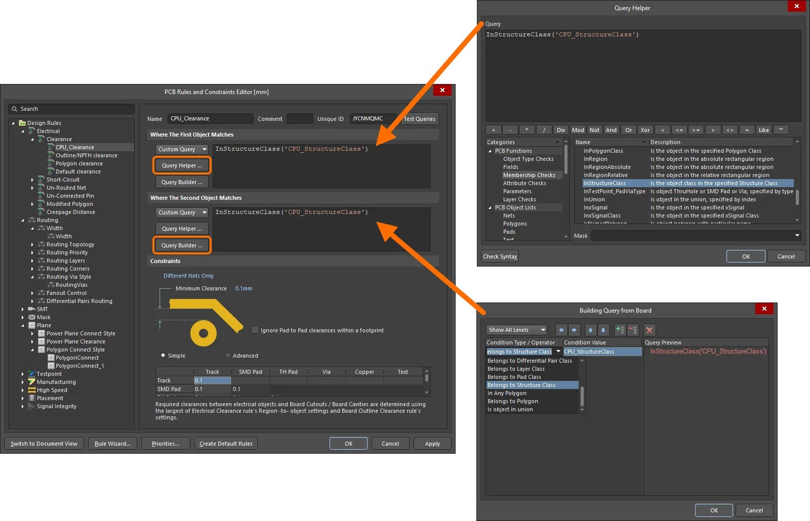
An example clearance rule between member objects contained within different Structure Classes.
Use this keyword when creating a logical query to be used in a filter expression – to quickly filter all low-level member objects descending from within the specified Structure Class.
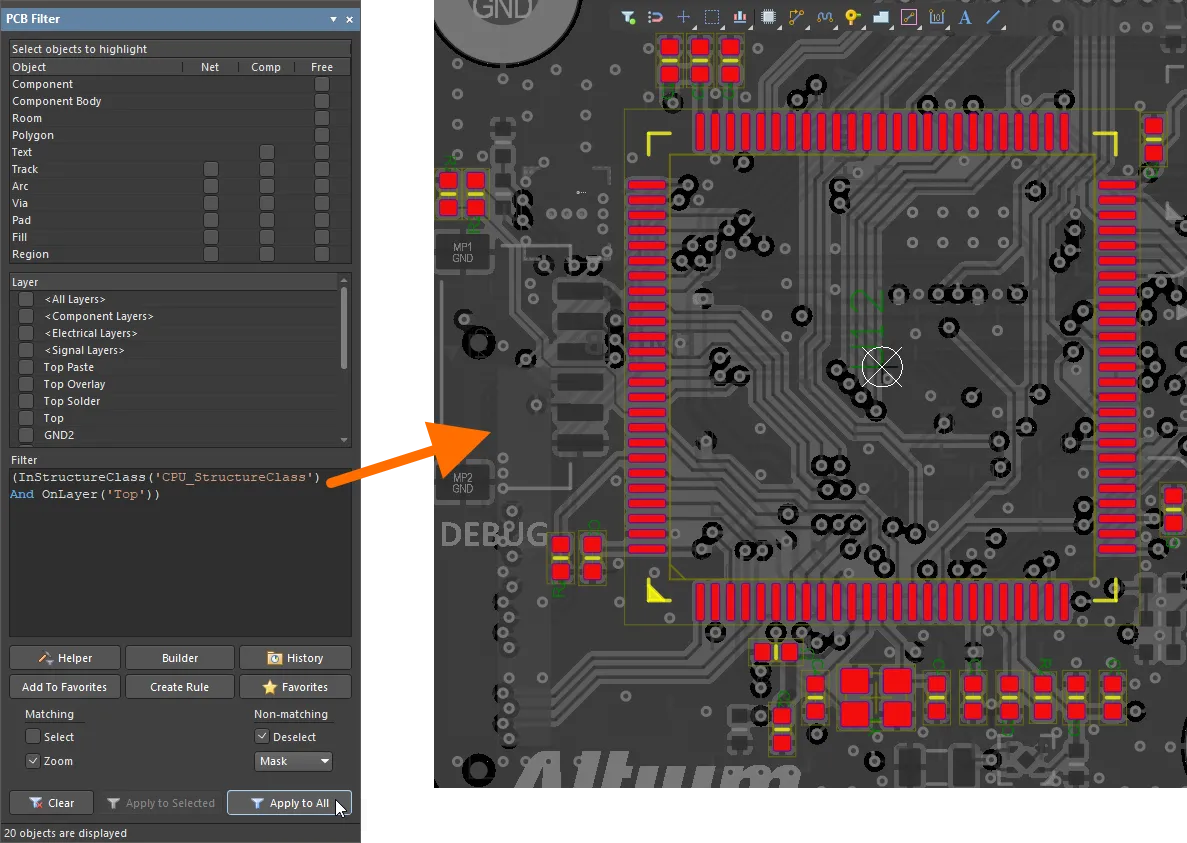
Quickly filtering all objects belonging to a particular Structure Class within the design space.