A Draftsman Bill Of Materials is an automatically generated table object that lists the physical assembly items in a PCB design. The BOM table data is derived directly from the project PCB file, or if one is present in the current project, an Active BOM document. A Draftsman BOM Table can also represent the constituent items from a specified design Variation or a placed Board Assemby View.
The BOM table's visual style and included data content is configurable in (or via) the Properties panel.
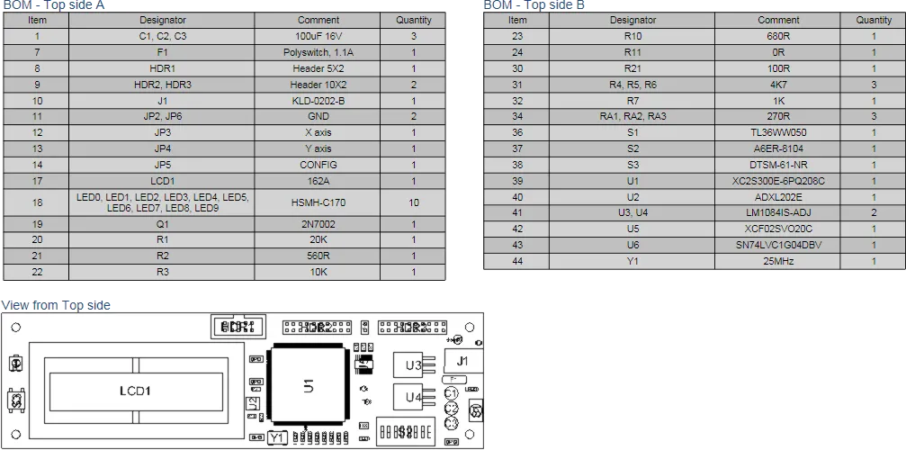
A Bill Of Materials table split over two BOM objects. In the above example, the BOM content is filtered to include the items from the Top side Board Assembly View.
To place a BOM table, select the BOM table placement tool  . After launching the command, BOM data is retrieved from the source PCB file or Active BOM document, the cursor will change to a cross-hair and the generated BOM table is attached to the cursor. Move the cursor to the desired position then click to confirm the placement.
Note that BOM data is retrieved from the PCB document specified in the Source section of the Properties panel when in Document Options mode. To change the panel to that mode, deselect all objects in the design space (click in free space).
The position of a placed Bill Of Materials may be graphically changed by selecting the table in the design space then dragging it to a new location. Note that the table cannot be graphically resized, but will automatically scale to accommodate the font style/size as specified in the Properties panel.
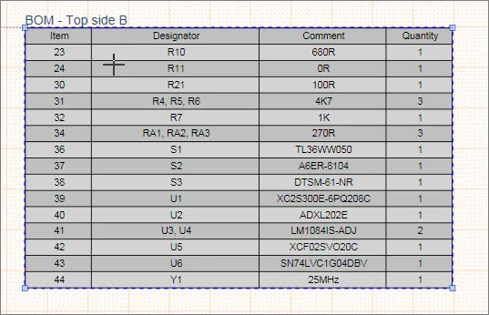
The data included in a Draftsman BOM table is determined by settings in the Properties panel and the potential presence of an ActiveBOM document in the project:
- When an ActiveBOM document is available in the current project, its configuration and content becomes the data source for a Draftsman BOM Table. Note that this applies when the Data Source entry in the Properties panel is set to Project – an available ActiveBOM document is not used as a source when the Data Source property is set to Board.
- When an ActiveBOM document is not included in the project (or the Data Source option is set to Board), the data in a Draftsman BOM Table is drawn directly from the source project files. An Alias entry for a table column entry Name (available in under the Properties panel’s Columns tab) is then editable since it is not determined by an Alias property entry in an ActiveBOM document.
In general, the Properties panel options can restrict BOM entries to those included in the Board layout (as opposed to the entire PCB project, including any custom component Parameters) or to a specific Variation of the design. Further tailoring of the included entries is available through specifying the top or bottom view of a placed Board Assembly View.
Use the Properties panel's Columns tab to manage the BOM table's data columns. This allows control of the BOM table column visibility, text alignment, width, and data sort order. BOM Table headings may be changed by entering an Alias for a table column parameter name – applies if an ActiveBOM document is not determining the table content (see above).
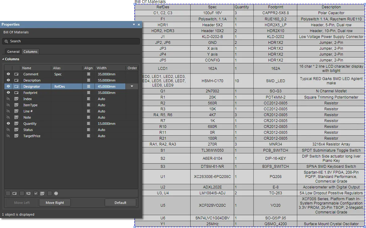
Manipulate the columns of a placed BOM Table in the Columns tab of the Properties panel.
Split BOM tables
The Bill of Materials (BOM) document for most advanced PCB projects tends to have a large number of entries, which can be difficult to recreate as a table that will fit into a drawing document. Rather than resorting to font and table scaling, multiple custom table entries or an external document, the Split BOM capability in the Properties panel allows a BOM Table to be presented over a number of 'pages'.
To create the multiple BOM Pages, select a placed BOM (which is likely to exceed the document Sheet height) and check the Limit Page Height box in the Properties panel’s Pages section. This will restrict the height of the BOM table to the nominated height entry (Max Page Height, mm), and therefore the number of lines shown in the BOM table.
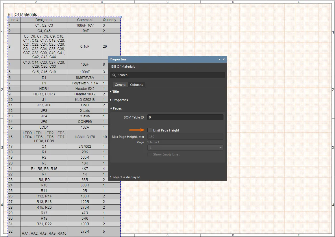
Hover mouse cursor over image to see the Limit Page Height result.
Draftsman detects that the entire BOM is not shown, as indicated by the panel's Page entry (for example, 1 from 2), and the associated drop-down menu allows you to nominate which Page is shown. To add further Pages of the BOM (here, BOM Table ID: 0), place another BOM (Place » Bill of Materials) and specify the next page under Page in the Pages section of the Properties panel.
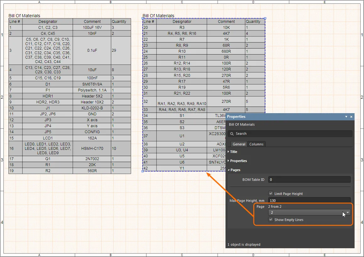
Since each Page of the BOM is placed by adding another BOM table, and then configuring it accordingly, the individual BOM Pages (sections) can be placed on any Sheet in a Draftsman document. To place another, different set of split BOM Pages, specify an alternative BOM Table ID on a placed BOM – say, 1 rather than 0.
Note that the Max Page Height property specifies the height of the first page in the BOM Table. When the second page is selected (Page 2), the Max Page Height property is defining the height of the first excluded page (Page 1). Page 2 therefore shows the remaining BOM entries. Start by making the Max Page Height property identical for each page.
Bill Of Materials Properties
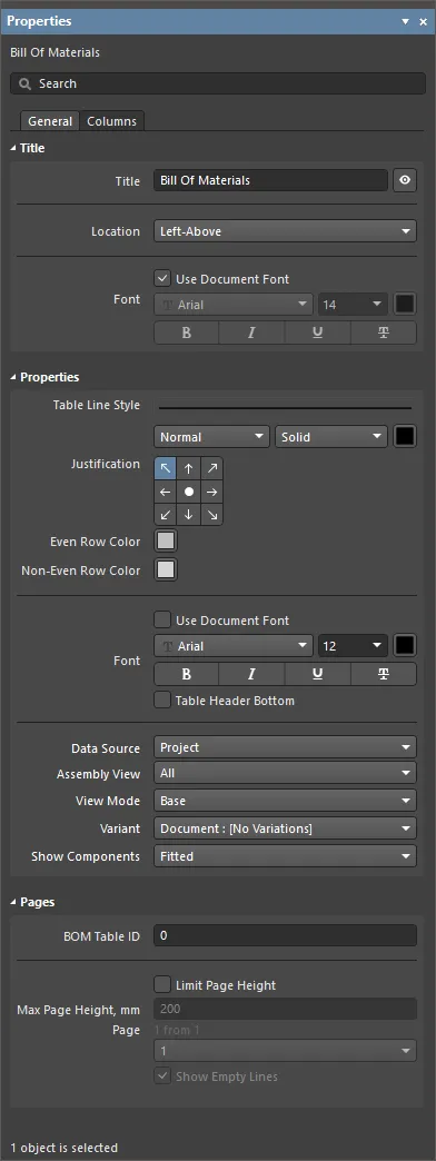
The Bill Of Materials mode of the Properties panel.
General Tab
Title
- Title – the title name string that will be displayed (if enabled) with the Bill Of Materials table. Use the associated
 button to toggle its visibility. Enter the title name and any desired system/custom parameters to create a meaningful name for the placed view. See the Parameters section in the panel's Document Options mode for a list of the currently available parameters.
- Location – select the drop-down to choose from a range of relative locations for the title. The Manual option is automatically selected if the title is manually moved (dragged and dropped to a new location).
- Font – sets the displayed font used for the table's title string.
- Use Document Font checkbox selected – the title font used is that defined by the document options. See the Document Font entry in General section of the Properties panel when in Document Options mode.
- Use Document Font not selected – use the drop-down menus to choose the desired font type and size, and select the lower buttons to enable text attributes. The associated color button (
 ) opens the color selector where the font color can be specified by RGB or HEX value, by freeform selection, or from a range of presets. Note that the slider control sets the color Opacity level, where 0% represents full transparency.
Properties
Pages
Use this section to configure split BOM tables.
- BOM Table ID – a numeric identifier for a BOM table instance. The complete table may be split over several BOM table objects (pages) and the ID remains in common.
- Limit Page Height – when checked, the BOM table is divided into a sequence of virtual pages each with the height specified in the Max Page Height property.
- Max Page Height – sets the height, and therefore, the included number of rows, in each page of the table. Only one page is included in a placed BOM table object (see Page below), and additional BOM table objects are placed to cover all pages.
- Page – indicates the table page number (
1 from 2, 3 from 5 etc.,) that is shown in the selected BOM table object. Use the associated drop-down menu to specify the desired page for the currently selected BOM table object.
- Show Empty Lines – when checked, blank rows in the BOM table are shown. These are typically on the last page of a BOM table where the specified page height has exceeded the number of available BOM data rows.
Columns Tab
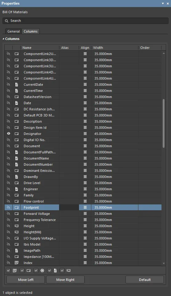
Columns
A tabular list of the columns and data shown in the BOM table. The entries may be edited to specify the BOM table's included (visible) columns and their text alignment (Align - Properties panel only), width (Width) and displayed list sort order/priority (Order). Enter an alternative name for a BOM Table header in its corresponding Alias entry – note that this entry cannot be edited if an ActiveBOM document is determining the BOM Table data (see Properties – Data Source, above).
- Column Type filter checkboxes (Properties panel only) – check the Schematic (
 ), PCB (
 ), Server (
 ) and BOM (
 ) options to populate the available columns list with matching parameter data types. Deselect all types to list only those columns that are visible (
 ) in the BOM Table. See ActiveBOM for more information about parameter data sources.
- Move Left / Right buttons – click to move the selected entry up or down by one count, and therefore, to the left or right in the BOM table column order. Available for columns set to visible.
- Default button – click to restore the table columns to the default entries (as defined by the BOM table object Preferences).