Wire

A wire is a polyline electrical design primitive that is used to form electrical connections between points on a schematic. It is analogous to a physical wire.
Wire Object
Wires are only available for placement in the Schematic Editor by clicking Home | Circuit Elements | Wire from the main menus.

After launching the command, the cursor will change to a cross-hair and you will enter wire placement mode. Placement is made by performing the following sequence of actions:
- Click or press Enter to anchor the starting point for the wire.
- Position the cursor then click or press Enter to anchor a series of vertex points that define the shape of the wire.
- After placing the final vertex point, right-click or press Esc to complete placement of the wire.
- Continue placing further wire objects, or right-click or press Esc to exit placement mode.
- Use the Backspace or Delete keys to remove the last wire segment placed.
Placement Modes
When placing a wire there are three placement modes, two of which have Start and End sub-modes. The mode specifies how corners are created when placing wires and the angles at which wires can be placed. During placement:
- Press Shift+Spacebar to cycle through the 90 Degree, 45 Degree and Any Angle modes.
- While in the 90 Degree or 45 Degree mode (known as true orthogonal modes), press Spacebar to cycle between the Start and End sub-modes.
- During placement, the current placement mode is displayed in the Status bar. You can change modes at any time during wire placement.
- In modes other than Any Angle, the line segment attached to the cursor is a look ahead segment. The segment you are actually placing precedes this look-ahead segment.
 45 degree mode
 90 degree mode
 Any angle mode
Guided Wiring
Schematics have a definable electrical grid that makes it easy to define electrical connections between objects. As you are placing a wire, when the wall falls within the electrical grid range of another electrical object, the cursor will snap to the fixed object and a Hot Spot (red cross) will appear.

Hot Spot (Red Cross)
The Hot Spot guides you to where a valid connection can be made and automatically snaps the cursor to electrical connection points.
The electrical grid can be defined on the General tab of the Inspector panel in Document Options mode (Project | Content | Document Options). It is recommended that you set the electrical grid to be slightly smaller than the current snap grid or it becomes difficult to position electrical objects one snap grid apart.
Graphical Editing
This method of editing allows you to select a placed wire object directly in the design space and change its size and/or shape graphically.
When a wire object is selected, the following editing handles are available:

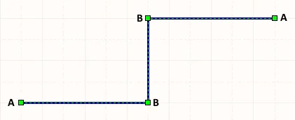
- Click and drag A to reposition the end points of the wire.
- Click and drag B to move a wire vertex. The end points will remain anchored.
- Ctrl+click and drag on a wire segment to grab that segment and reposition it. The end points and other vertices will remain anchored.
- Ctrl+click and hold on a wire segment, then press Insert on the keyboard to add a vertex at that point.
- Click and hold on a vertex, then press Delete on the keyboard to remove that vertex.
To move an entire wire, click and hold on the un-selected wire, then move to the new location.
A wire segment can also be removed through the use of the Break Wire command.
To clear the selection of (or de-select) the object, use the Esc key.
Non-Graphical Editing
This method of editing uses the Inspector panel to modify the properties of a wire object.

During placement, the Wire mode of the Inspector panel can be accessed by pressing the Tab key. Once the wire is placed, all options appear.
After placement, the Wire mode of the Inspector panel can be accessed in one of the following ways:
- If the Inspector panel is already open, select the wire object, right-click then choose Properties from the context menu.
- With the wire selected, choose View | Schematic | Inspector from the main menus.
Wire Properties
All Wire object properties are available for editing in the Inspector panel when a placed Wire is selected in the design space.

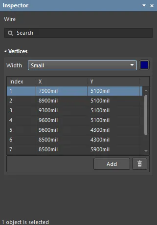
- Width - use the drop-down to select the desired width.
- Vertices Grid - lists all of the vertex points currently defined for the object in terms of:
- Index - the assigned index of the vertex (non-editable).
- X - the X (horizontal) coordinate for the vertex. Click to edit.
- Y - the Y (vertical) coordinate for the vertex. Click to edit.
- Add - click to add a new vertex point. The new vertex will be added below the currently focused vertex entry and will initially have the same X,Y coordinates as the focused entry. Click
 to remove the currently selected vertex.
Net Label

Net labels identify and electrically connect different points in a schematic.
Electrical connectivity between schematic component pins can be created by placing a wire between those pins. This is called physical connectivity since the pins are physically connected with a wire. Connectivity can also be created logically by using suitable net identifiers, such as net labels. As well as providing a human-friendly identifier for a net, a net label allows you to connect points on a circuit without actually physically wiring them together.
Net Label Object
Net labels are available for placement in the schematic editor only by clicking Home | Circuit Elements | Net Label from the main menus.

After launching the command, the cursor will change to a cross-hair and you will enter net label placement mode with a net label floating on the cursor:
- Press Tab to open the Inspector panel. The Net Label properties can be edited with the existing text selected ready for editing.
- If the net label requires rotation, press the Spacebar to rotate it in 90° increments. Press the X or Y keys to flip the net label along the X-axis or Y-axis respectively.
- Position the net label so that its bottom-left corner touches the object to which you want to assign it, then click or press Enter to place the net label.
- Continue placing further net labels or right-click or press Esc to exit placement mode.
The electrical hotspot on a net label is the lower-left corner; this corner must touch the wire, bus, or signal harness for a valid connection to be made.
The net label can be edited graphically, using what is known as in-place editing. To edit a net label string in-place, click once to select, pause for a second, then click a second time to enter edit mode.
 Click once to select the string.
 Pause, then click a second time to enter in-place edit mode.
 Here the string has been selected, ready to type in a replacement string.
Once editing is complete, press Enter or click away from the string to exit in-place editing mode.
An object that has its Locked property enabled cannot be selected or graphically edited. Double-click on the locked object directly then disable the Locked property to graphically edit the object.
Non-Graphical Editing
This method of editing uses the Inspector panel to modify the properties of a net label object.

During placement, the Net Label mode of the Inspector panel can be accessed by pressing the Tab key. Once the net label is placed, all options appear.
After placement, the Net Label mode of the Inspector panel can be accessed in one of the following ways:
- If the Inspector panel is already open, select the net label object, right-click then choose Properties from the context menu.
- With the net label selected, choose View | Schematic | Inspector from the main menus.
Notes
- Net labels create logical connectivity within a single schematic sheet; they do not create connectivity between schematic sheets. To do this, Ports must be used.
- To negate (include a bar over the top of) a net label, include a backslash character after each character in the net name (e.g., E\N\A\B\L\E).
- When individual nets form a bus, there are specific requirements as to how they are named. For more information refer to the Bus page.
- Net identifiers of different types do not automatically connect to one another even if they share the same name. For example, a net label named AGND will not automatically connect to a power port named AGND; a wire must be placed to connect them.
Net Label Properties
All Net Label object properties are available for editing in the Inspector panel when a placed Net Label is selected in the design space.

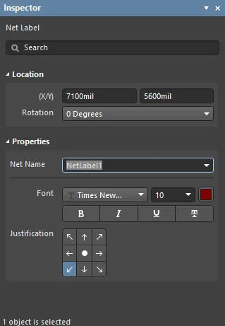
- (X/Y)-
- X (first field) - the current X (horizontal) coordinate of the reference point of the object, relative to the current design space origin. Edit to change the X position of the object. The value can be entered in either metric or imperial; include the units when entering a value whose units are not the current default.
- Y (second field) - the current Y (vertical) coordinate of the reference point of the object, relative to the current origin. Edit to change the Y position of the object. The value can be entered in either metric or imperial; include the units when entering a value whose units are not the current default.
- Rotation - use the drop-down to select the rotation.
- Net Name - use the drop-down to select the net name or enter the name directly.
- Font - use the controls to select the desired font, font size, color, and attributes to bold, italicize, etc., if desired.
- Justification - select the justification by clicking on an arrow that corresponds with the desired justification or the circle to center.
Break Wires
The Break Wires command is used to break a segment of a polyline object (wire, bus, or signal harness) into two pieces at a chosen location on the schematic sheet. The Break Wires command can be accessed from the schematic editor in the following ways:
- Select Tools | Convert | Break Wires from the main menus.

- Right-click over the segment of the polyline object then select Break Wire from the context menu.
After launching the command, the cursor will appear in accordance with settings defined for the Cutter Box, and Extremity Markers, on the Schematic - Graphical Editing page of the System Preferences.
Position the cursor over the segment of wire, bus, or signal harness that you want to effectively break into two then click, or press Enter. The indicated length of the segment will be removed, thereby breaking the segment into two.
Continue breaking further polyline objects, or right-click, or press Esc, to exit.
While in break wire mode, the following additional actions can be performed:
- Press the Spacebar to cycle through the following cutting length modes:
- Snap To Segment - in this mode, the cutter will auto-size to snap to an entire polyline segment.
- Snap Grid Size Multiple - in this mode, the cutter is sized to a defined multiple of the current snap grid.
- Fixed Length - in this mode, the cutter is sized to a defined fixed length.
Notes
- Regardless of the size of the cutter, other than Snap To Segment, the cutter will shrink to accommodate smaller-sized wire segments in their entirety - as it passes over them - as though Snap To Segment were selected.
- You can also remove selected wire segments (not segments of bus or signal harness objects) with the tap of the Delete key, with auto-junctions also accounted for - allowing you to remove a segment of a wire up to that junction only (and including that junction if only two other wire segments would otherwise remain connected to it). Simply click twice (with a pause in between) on a particular segment of wire to select it, denoted by its end-point editing handles turning red. You can delete multiple segments across different wires, ensure that each is selected (Shift+click twice on each subsequent segment to include it in the overall segment selection).
Set Net Colors
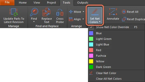
Net color commands are accessed from the schematic editor by choosing Tools | Net Colors | Set Net Colors from the main menus.

As the design builds up it quickly becomes dense and detailed - the schematic busy with wiring and the board a maze of connection lines and routed nets. To help bring clarity and visibility, the designer can apply color to the schematic wiring, PCB connection lines, and routing.
The ability to selectively override the color of specific nets is known as Net Color Override. Color can be applied to schematic nets and those color settings transferred to the PCB, or color settings can be applied directly from the PCB Editor's PCB panel.
Toggle Net Color Override on or off in the schematic seditor with the F5 shortcut key.
Applying Color to the Schematic Nets
Click on a pin, wire, bus, or net identifier (net label, sheet entry, port, power port, or offsheet connector) to apply the selected color to that net (or all the nets in a bus). The command remains active after clicking on the first net, ready to color subsequent nets in that same color if required.
When a color is applied to a net or a bus, it overrides any previous color setting. Note that net color settings cannot be undone, to remove a color setting use the Clear Net Color command or the Clear All Net Colors command.
The color is automatically applied to all sections of the net, on all schematic sheets in the project. This occurs automatically when the background compiler updates the connectivity of each sheet.
To include color on a net or bus that connects two sheet symbols, include a net label on the net/bus running between the sheet symbols.
Color is not applied to a component pin or a power port, drag them apart to add a wire if there is no color showing on that section of net.
The color setting for a net is not stored with the various objects placed on the sheets. The color settings are actually stored in the project file as a net-level setting and are applied on each schematic sheet after it is opened and the background compiler has compiled that sheet.