Altium Designer Software Subscription Levels

Choose the level that’s best for you.

STANDARD

Efficiency

For Electronic Designers

For professional electronic designers and engineers to design PCBs and share projects with stakeholders.

PRO

Productivity

For Product Designers & Small Teams

For cross-functional teams designing electronic products to collaborate efficiently.

ENTERPRISE

Digital continuity and managed processes

For Organizations

For organizations to establish digital continuity and manage processes to help ensure product quality, faster time-to-market, and compliance.

Amazon
dell
karcher
square
siemens
arduino

Standard

Pro

Enterprise

Standard

For professional PCB designers and engineers to design PCBs with ease.

Pro

For teams designing electronic products to efficiently collaborate within engineering and adjacent domains.

Enterprise

For organizations to establish digital continuity and manage processes to help ensure product quality, faster time-to-market, and compliance.

Altium Designer

Standard

Pro

Enterprise

Software Updates
Maintain access to the latest Altium Designer updates as they are released.
Unified Design Environment
Provides a single environment for every aspect of the PCB design process including schematic capture, PCB layout, multi-board assembly, harness design, library management, simulation, documentation, and more.

Multisite License Support

Standard

Pro

Enterprise

Single Site
This license type can be used in one location only. Learn More
Continental
This license type can be used within one continent. Learn More
Global
This license type can be used anywhere. Learn More

Schematic Capture

Standard

Pro

Enterprise

Hierarchical & Multi-Channel Design
Enables the creation of designs at a block diagram top-level, where projects can be split into manageable logical chunks. Hierarchical design also allows you to create multiple copies of the same block when you need multiple channels of an identical circuit.
Schematic Design Rules
Use automated rules that help you to correctly lay out a PCB. Design rules can be added to schematics for nets, wires, busses, harnesses, components, sheets, or document parameters.
Electrical Rule Checks
Helps prevent design mistakes by alerting you to problems in a schematic like electrical faults. These validation checks will be performed after any change is made to a design and on every release.
Design Process Automation
Add cross-references to a project that allow you to easily follow the connective flow of nets between the schematic sheets in a project. All sheets are automatically numbered to help keep your designs organized.
Design Importer
Leverage previous designs to reduce time re-creating schematics, board layouts, and associated design data with an automatic importer of project files from your preferred PCB design tool. Supports P-CAD®, Autodesk® EAGLE™, Cadence® Allegro®, Cadence® OrCAD®, KiCad®, LTspice®, Mentor Graphics® DxDesigner®, Mentor Graphics® Expedition®, Mentor Graphics® PADS®, Mentor Graphics® xDxDesigner®, Simbeor®, Zuken® CADSTAR®, and Zuken® CR-5000®.

Simulations

Standard

Pro

Enterprise

Ansys CoDesign
Digital connection between Altium software and Ansys Electronics Desktop (AEDT) to enable streamlined exchange of data and seamless collaboration between electrical and simulation engineers, replacing manual and error-prone data exchange and communication methods.
Integrated SPICE Simulation
Create and manage multiple simulation profiles. Separate profiles allow you to run different types of analyses with different simulation engines (e.g., Mixed Sim, SIMetrix, SIMPLIS). This enables multiple runs of the same simulation type (e.g., AC or DC analysis) with different parameters and options (e.g., different frequency ranges).
LTSpice Importer
Simulation designs saved from LTspice® can be imported into Altium Designer with the LTSpice Import Wizard. Component symbol files referenced by the LTSpice design file (*.asc) are automatically added as library files, and in turn, the simulation models referenced within the component library files are also added to the import.

Board Layout

Standard

Pro

Enterprise

PCB CoDesign
Allows engineers and teams to work simultaneously on the same project, enabling engineers to dramatically compress design cycles and accelerate the overall design process.
Rules-Driven Design
Define specific manufacturing guidelines with a customizable design rule system including specifications for board outlines, solder mask expansions, drill placement, and an advanced query editor to create non-standard rules.
Visual Layer Stack Management
Define the material composition and specialized regions on a board. For flex circuitry, rigid-flex, and embedded technology PCB designs, you can control the entire stackup, including all rigid and flex portions with bending angles and individual layer definitions. You can visualize layer stacks using subsets of materials used in the primary layer stack, and each layer has an individual definition and corresponding parametric data from a Materials Library.
Constraint Manager
Centralizes rules and constraints management with a unified table-based editor in both the schematic and PCB editors consolidating all electrical and physical design rules. Constraint sets can be reused between designs to save time when constraining new projects.
Materials Library
Define system-wide parametric data on any materials you may specify in the construction of your layer stack. You can create any new material you intend to use, or use the set of generic ones already available, and the materials library can be saved and loaded to XML - so you can share it with your entire team.
HDI Design
Enables accurate design and visualization of HDI structures, including laser-drilled and mechanical microvias, stacked microvias, and skip-vias. A dedicated Layer Stack Manager allows you to define what µVia, blind/buried and other via structures you can allow in your project, and control the layer stack symmetry accordingly.
3D-MID Design
Currently in open beta. Create a non-planer design (3D-MID) by synchronizing components and connectivity from the schematic into a new dedicated layout type, and edit directly on the surface of a 3D substrate. You can export the manufacturing data in the format required by the Laser Direct Structuring process. Learn more
Copper Pour Management
Create areas of copper for power and signal planes that can be defined using three different design objects: Fills, Solid Regions and Polygon Pours. You can control the placement (pour) order and temporarily disable (shelve) regions to make it easier to see your underlying PCB layout.
Precise Object Placement
Facilitate routing and avoid physical collisions with the use of rooms, keepouts, and polygon regions to aid you when designing. Rooms are regions that assist in the placement of components by grouping them inside a designated area. Keepout regions act as an ‘interference’ object that prevents other copper objects from intersecting its area.
Rigid-Flex Design
Design today’s flexible circuitry in full 3D as part of a complete electronics product. Allows you to confirm that 3D components, case assembly, and PCB clearances meet your manufacturing requirements in real-time. Layer Stack Regions allow a single board to be composed of multiple materials, flexibility, and thickness, enabling the design of Rigid-Flex-Rigid PCB assemblies.
High-Speed Design
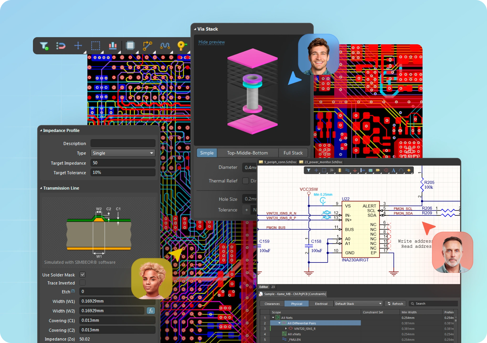
Design high-speed electronics with a powerful tuning engine. Includes advanced pattern support, an EM solver for accurate propagation delay, impedance extraction, and Easy HDI structure integration.
Impedance Profiles
Accurately control trace impedances (single and differential pairs) to maintain signal integrity in your high-speed designs. Impedance profiles use a fast, accurate 2D field solver to calculate impedances from trace widths, and trace widths and spacings from impedances. Single-ended and differential microstrip or striplines including asymmetric planes can be specified using plane layers or signal layers as references.
Counterholes Support
Provide room for screw heads in a PCB laminate. You can add one counterbore or countersink hole per pad in a PCB design. This capability is supported in 2D, 3D, and in manufacturing drawings.
PCB Layout Replication
Easily duplicate layouts for repetitive circuit blocks by transferring the design structure from one group of components to another identical group. Fragments of a PCB with the same components and connectivity are instantly identified and then copied without having to worry about managing reuse blocks or manually matching components.
Custom Pad Stack
Make a custom pad shape and define the location of conductors as part of a custom pad stack.Thermal relief connections are supported for custom shape pads to both solid and hatched polygons. You can choose to use conductors from each side of the pad region or use a selected number of conductors. A custom shape pad can also have a custom Solder and/or Paste Mask.
Native 3D PCB Design
Interact and collaborate with mechanical designers in a photo-realistic, 3D design environment to confirm fit and connectivity. You can also add rigid-flex sections to a PCB design with bikini coverlay support and check clearances in 3D.
Sectional View
Unveil hidden details within a PCB which might be obscured in the standard 3D view. This is particularly useful when dealing with measuring or moving smaller SMD components positioned beneath larger components or mechanical parts.
Panelization Support
Prepare panels for a new design in much the same way as you would a single PCB. You can then generate Gerber files for your PCB panel and other standard deliverables in a single design environment.
IPC-4761 Support
Altium Designer supports vias types according to IPC-4761 including covering, filling, plugging, capping, and tenting. when an IPC-4761 via is placed in a PCB design, new types of mechanical layers and component layer pairs are automatically added to the design, with corresponding shapes on these layers. These new layers are then available for PCB printouts, Gerber and Gerber X2, ODB++, IPC-2581 outputs.

Interactive Routing

Standard

Pro

Enterprise

Interactive Routing Modes
Interactively route a board with several powerful routing options including walk around, push, hug and push, ignore obstacle, push & shove.
Automated Multi-Net Routing
Route multiple nets simultaneously for groups of signals to all need to be routed along the same path, such as for Address and Data busses.
Trace Length Tuning
Automatically align routing path lengths without ever having to waste time manually adjusting individual nets with interactive length tuning.
Automatic Multi-Net Tuning
Improve PCB design accuracy and efficiency by automatically adjusting multiple nets at the same time to meet specific design rules, including length and delay. Works with differential pairs and traces of any angle.
High-Speed Signal Routing
The xSignals wizard lets you easily plan and constrain your high-speed designs by defining high-speed signal paths for modern interfaces . You can route high-speed designs with fully configurable differential pair routings that carry precise signal lengths across a PCB. DDR3/4 and USB3.0 signals are automatically identified by the wizard which creates rules to keep all signals in sync and tuned to the correct length.
High-Speed Design Rules
Deliver consistent impedance in your high-speed design projects. A Layer Stack Manager is capable of automatically selecting the geometric parameters of a track based on layers, structures and specified target impedance, and generates a defined impedance profile ready for use in design rules.
HDI Routing
HDI designs are supported by high-performance routing tools in Altium Designer including automatic fanout placement, via in pad, and removal of unused via shapes.
Visual Clearance Checking
See clearance boundaries between traces and components during route placement. This allows you to route through high-density areas with certainty that traces fit where they need to, and you get immediate feedback on how route placement changes a layout and how it will change future routes.
Glossing & Retrace Engine
Provides powerful tools for improving the quality of existing routing. Whenever you move the cursor to define a new route path, all of the proposed routing is automatically glossed. Glossing will attempt to reduce the path length, and also improve the shape of corners and reduce their number. Retracing can also be used to check and update routing to your current design rule settings.
Automated BGA Fanout
Allows you to implement neck-down as you route into a BGA. Single-ended and differential pair width rules for a design can be configured for a specific copper neck-down, which saves you time when routing a dense BGA.
Pin & Part Swapping
During a pin swap operation, Altium Designer analyzes the net assigned to the chosen pin, and dynamically reassigns the net on the pin and any connected copper. Partially routed nets and pre-routed multilayer escapes from complex BGA devices can be swapped. Differential pairs can also be swapped, taking advantage of the knowledge about differential pin-pairs on FPGAs.

Product Design

Standard

Pro

Enterprise

Multiboard Schematic
Create board-to-board connectivity and verify net-to-pin assignments and pin-to-pin interconnects. Changes and updates can be pushed down into affected PCB projects or bought back up to the source system schematic. A system-level BOM can be created to provide a single source BOM across the multi-board project, eliminating the need to manually combine individual sub-project BOMs.
Multiboard Mechanical Integration
Allows each separate board to be rotated and aligned with each other. Additional parts, boards, assemblies, or STEP models can also be imported and positioned within the multi-board assembly.
Multiboard Assembly
A physical counterpart to the logical system design in a multi-board schematic which is populated with imported PCB data from the multi-board project. Each PCB module in the system design schematic is represented by a physical PCB.
Harness Design
Harness MCAD CoDesign*
Optimize harness designs and detect potential problems for wiring inside electronic enclosures by keeping harness designs synchronized between Altium Designer and PTC Creo®. Easily import 3D wire harness models into multi-board assemblies.

Manufacturing & Documentation

Standard

Pro

Enterprise

Automated Output Generation
Add verified project snapshots into an Altium 365 Workspace, or desired folder structure with a streamlined project releaser. You can dynamically create customized project outputs for design variants linking fabrication and assembly outputs with the latest design source files.
Visual Manufacturing Outputs
Once image and drill files have been imported into Altium Designer, a CAM editor can extract a physical connectivity netlist and compare it with an IPC netlist generated from the original PCB design software. These netlists will handle not just through- hole components, but also blind and buried vias as well. The CAM Editor also offers Design for Manufacturing (DFM) rule checking, copper thieving, panelization, and NC-Routing (plus milling) tools.
Integrated Drawing Tools
Create assembly and fabrication documentation directly linked to source designs with Draftsman® and update your entire documentation at the click of a button.
Multiboard Drawing Tools
Improve the efficiency of design reviews and assembly precision by providing a unified approach to complex assembly visualization and documentation for MultibBoard Designs.
Customizable Drawing Templates
Create templates for drawings that require minimal customization across designs. This allows you to add PCB dimensions, measurements, notes, and callouts between points of interest and design objects to customize your documentation workflow.
Output & Assembly Steps Web Viewer
From any device with a browser you can compare Gerbers before sending them to manufacturing, access the layerstack for your board, take measurements, cross probe components/nets, step through a board assembly process, and more.

Platform Services

Standard

Pro

Enterprise

Workspace
A Workspace is a secure and private environment for all of your data and the people you invite to work together.
Multiple Workspaces
Set up separate workspaces for a variety of teams and departments.

Design Review & Sharing

Standard

Pro

Enterprise

Live Design Sharing
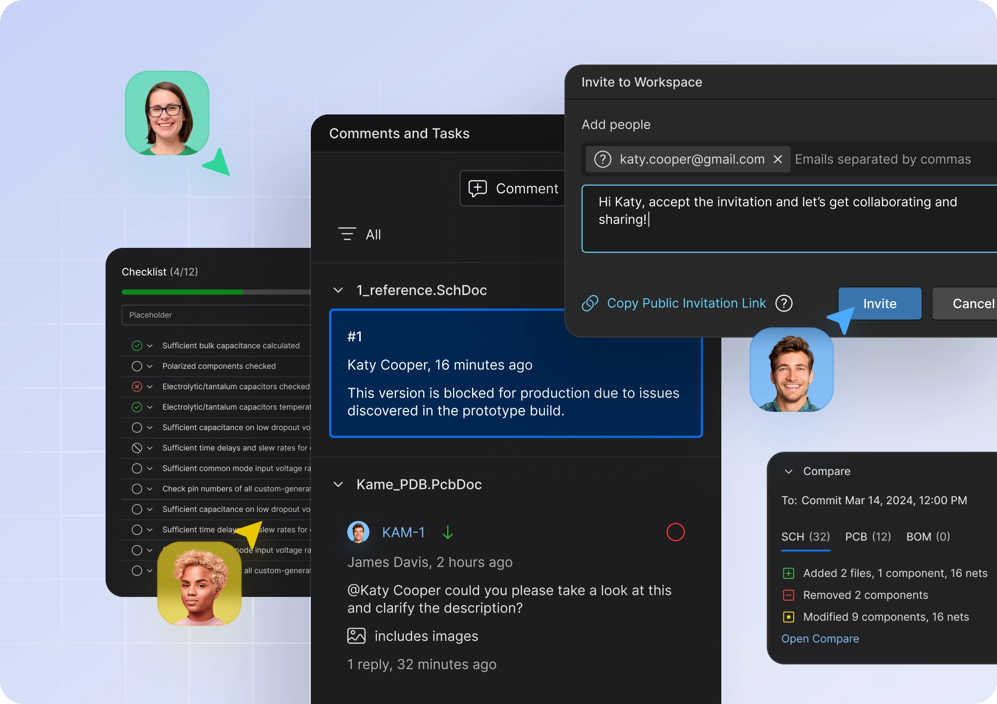
Share your projects with as many people as you need at no additional cost. All of your project stakeholders can view, measure, search, cross-probe, and comment on your live design, seeing all of the latest changes and updates right in the browser. Learn more
Interactive Commenting
Comment to an entire document or a specific object, highlight the problem area directly in the design, and tag people and get them straight to the context of your comment, all without leaving your design environment. Learn more
Context-Aware Tasks
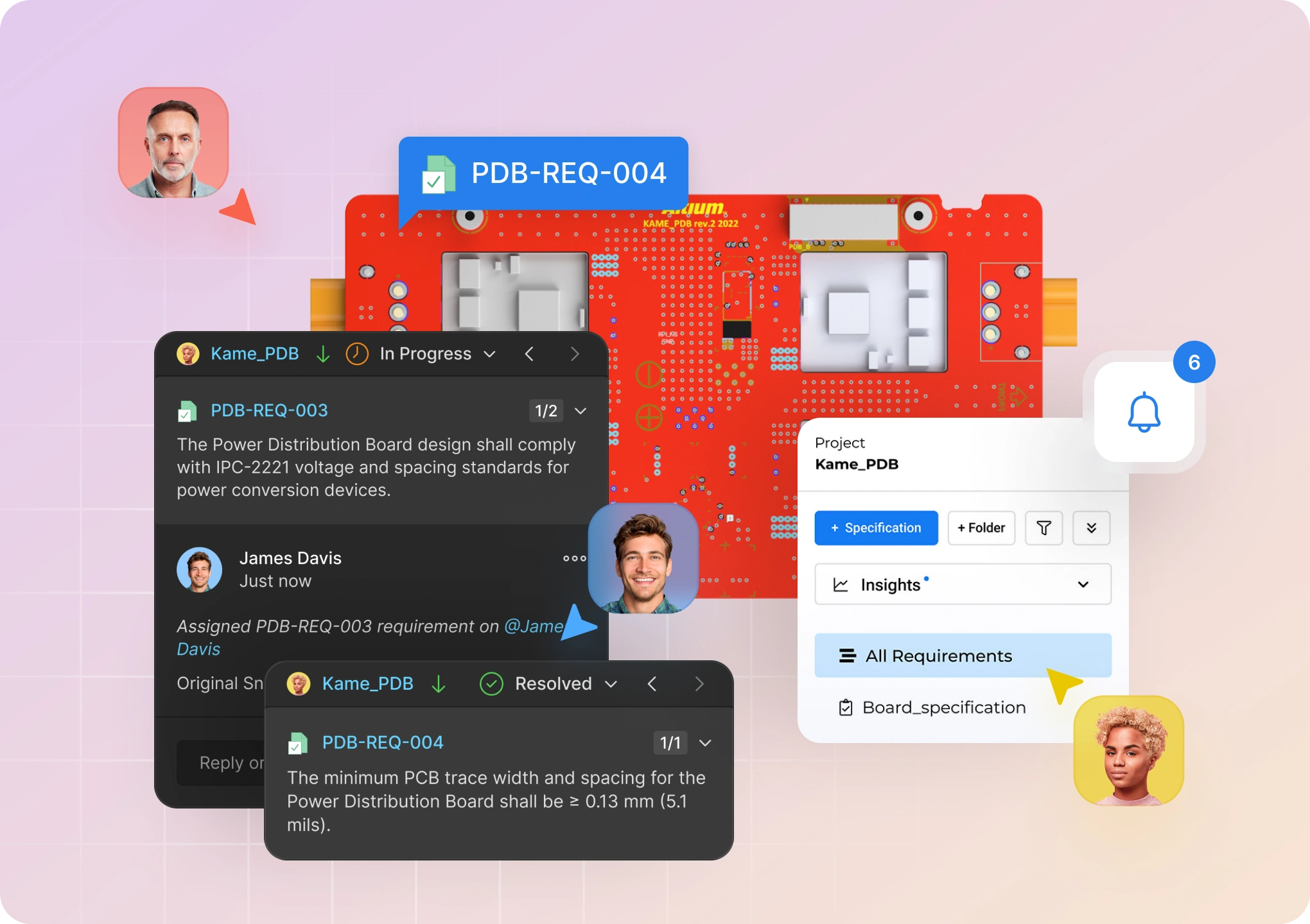
Never lose an important action item, easily get a high-level view of the state of your project, all without leaving your design environment. Learn more

Mechanical (MCAD) Integration

Standard

Pro

Enterprise

Basic ECAD-MCAD Co-Design
Enable bi-directional communication between ECAD and MCAD (SOLIDWORKS®, PTC Creo® Parametric™, Autodesk Inventor®,Autodesk Fusion 360®) domains, allowing changes to be reflected and updated on either side. Learn more
Sync Keepout and Rooms*
Synchronize and update PCB keepout areas in both ECAD and MCAD environments.
Advanced Copper Geometry*
Create precise copper 3D models in MCAD (including vias and plated pad barrels) for FEA purposes, advanced mechanical checks, etc. Available for SOLIDWORKS®, PTC Creo® Parametric™, Autodesk Inventor®, Siemens NX™. Learn more
Rigid-Flex Synchronization*
Collaborate on the design of rigid-flex boards with mechanical engineers who use SOLIDWORKS® and PTC Creo® Parametric™. Learn more. Learn more
MCAD-driven Component Placement*
Place components in MCAD so that they are recognized in ECAD (available for SOLIDWORKS®, PTC Creo® Parametric™, Autodesk Inventor®), or use the native MCAD components when transferring PCB from ECAD to MCAD (available for SOLIDWORKS®, PTC Creo® Parametric™). Learn more
Enclosure Exchange*
Send a mechanical enclosure from MCAD to ECAD directly from your device assembly and simplify the design process in ECAD. Available for SOLIDWORKS®, PTC Creo® Parametric™, Autodesk Inventor®. Learn more
Advanced History*
View the detailed history of accepted and rejected changes between the electrical and mechanical teams, along with the rejection comments. Learn more
Pull a Previous Revision*
Ability to select which revision to Pull from a list of previous Pushes in MCAD. Learn more
Multiboard Assembly Synchronization*
For Multiboard projects, synchronize the entire Multiboard Assembly (the full set of PCBs and the mechanical enclosure) at once and simplify checking the overall product layout in ECAD. Available for SOLIDWORKS®, PTC Creo® Parametric™. Learn more
Harness Design Synchronization*
Transfer the source data for 3D routing of Harness from ECAD to MCAD (connectors, wires, splices, connectivity, and harness topology) and get the physical length of wires, cables, and harness segments in ECAD. Available for SOLIDWORKS®, PTC Creo® Parametric™. Learn More

Integrates with

Standard

Pro

Enterprise

SOLIDWORKS®
PTC Creo® Parametric™
Autodesk Inventor®
Autodesk® Fusion 360™
Siemens NX

PLM Integration

Standard

Pro

Enterprise

Bi-directional Component Sync
"Ensure consistency between ECAD and PLM with component metadata synchronization (Arena, Winchill, Agile*, and Teamcenter*) *Supported on-prem only"
Release & Publish to PLM
Leverage configurable and automatic generation of manufacturing deliverables along with direct release and archive to PLM to ensure release data is accurate and complete. (Arena, Windchill, Agile*, and Teamcenter*) *Supported on-prem only
Project Creation linked to PLM
Create an initial project data structure from ECAD directly into PLM, capturing all of your company-specific project parameters to drive efficiency and enterprise-wide transparency.

Integrates With

Standard

Pro

Enterprise

Arena® PLM
PTC Windchill
Aras PLM
Oracle Agile PLM
Available only On-Prem
Teamcenter®
Available only On-Prem

Design Data Storage

Standard

Pro

Enterprise

Design Storage and Version Control
Store and access all of your design assets in one centralized location in the cloud with full visibility of the changes made. Storage in Pro is Up to 10 GB
Up to 10 GB
Up to 10 GB
Up to 10 GB
Project History
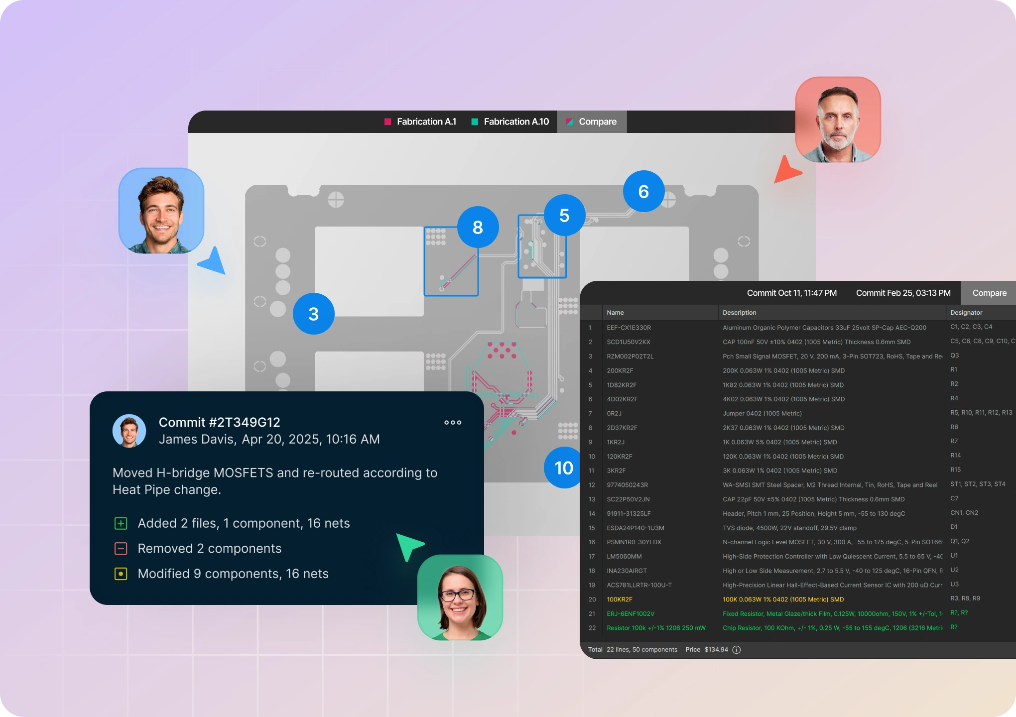
Review every change that happens to your designs, including details like net and component modifications, with in-depth search capabilities for modified data.
Design Reuse
Manage schematic sheets, reusable layer stacks, design templates, and defaults.
Manufacturing Data Archive
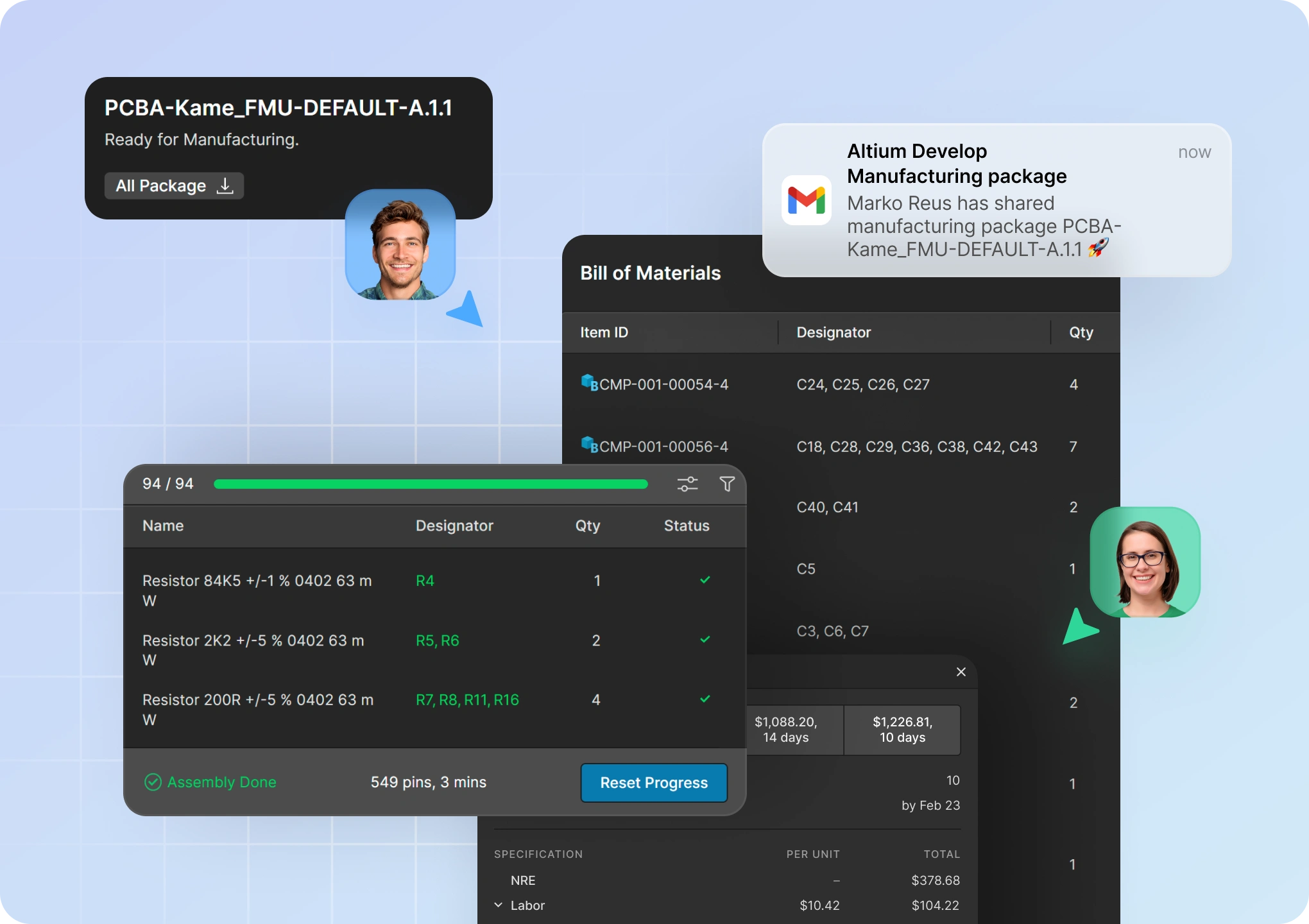
Store and manage all of your releases, form manufacturing packages and communicate changes with the manufacturer, all in one place.
Configurable Lifecycle Management
Define lifecycle states and assign them to design data, including components with models, managed schematics, and releases.
Release Management
Generate a complete manufacturing package for going to prototype and production. The release process is completely repeatable, letting you create templates and preset output jobs that guarantee the same formatting and collection of design CAM (Fabrication), Documentation, Validation, and Assembly outputs.
Variant Management
Create designs with different functionality on the same board using project variants. The Variant Manager focuses on the functionalities of your PCB as a whole instead of individual parts. By defining a group of components in the Variant Manager, you can launch a whole line of devices with different characteristics and satisfy the needs of a wide range of users.

Centralized Libraries and Supply Chain

Standard

Pro

Enterprise

Manufacturer Part Search
Rapidly find which parts are available and at what cost - right at design time. You can also choose backup parts that meet your budget, availability and design requirements.
Real-Time BOM Management
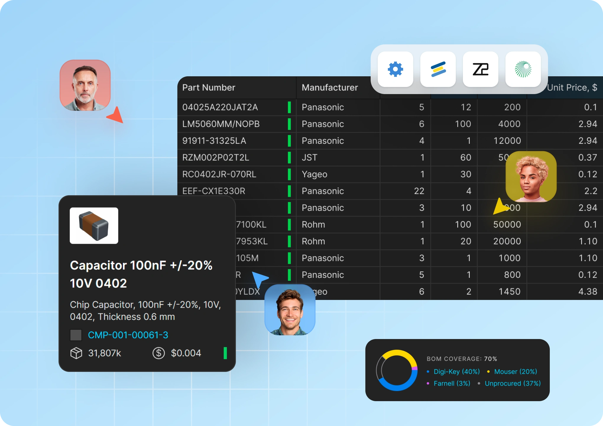
ActiveBOM automates the supply of part information such as availability and price from selected suppliers. Altium Designer allows you to specify pin-compatible backup part choices directly in BOM, which nearly eliminates supply chain issue risks for manufacturing.
IPC Compliant Footprint Wizards
Any part you need can be rapidly and accurately built to match your own library standards while also meeting the fabrication and assembly quality and layout set forth by IPC-7351, SM-782 and JEDEC (through hole). You can even batch-produce whole families of footprints from an Excel sheet or CSV file.
Cloud Libraries
Easy-to-use design libraries stored in a centralized, secure, and version-controlled cloud platform.
Intelligent Supply Chain
Control the list of manufacturing parts associated with the components in your design and always have up-to-date information about their status and availability.
Octopart Library Content
Access models, parameters, and basic lifecycle data for millions of electronic components in Octopart
Managed Components
Formal data management for design library components, including support for lifecycle states, in-design validation, templates, and where-used traceability.
Component Data Link
Load component data from other external sources, including CSV, Excel, and ODBC.
IHS Markit® Component Intelligence
Advanced component data from IHS Markit.
Library Health Dashboard
Proactively monitor design libraries for validity, quality, and potential issues.

Teamwork

Standard

Pro

Enterprise

User Management
Manage workspace access for people inside and outside of your organization.
Change Notification
Receive notifications regarding design changes through Altium Designer, Altium 365, or by email.
Role and Group Management
Organize users into groups with granular access rights.
Support for Single Sign-on (SSO)**
Connect with popular SSO identity services via the SAML protocol.
Change Conflict Prevention
Prevent edit conflicts with instant notifications in Altium Designer when several people start editing the same document.
Operation Permissions Support
Finely control major operational availability for all the team members and groups in your organization.
Team Configuration Center
Manage tool configuration, content usage, and setup across all teams.

Workflows and Processes

Standard

Pro

Enterprise

Part Request
With a managed workflow, automatically initiate the request process, electronically communicate with the librarian, and receive automated notifications when the validated part is ready for use.
Unmanaged
Managed
Managed Design Review
Enable cross-domain design teams and stakeholders to easily collaborate providing feedback and needed changes directly within design documents. Team members can review, mark-up, provide comments, and assign actions eliminating manual methods and miscommunications.
Managed Project Creation
Capture all of your company-specific project and required parameters every time a new project is created.
Managed Project Release
Leverage an advanced approach to organizing, tracking and storing the design output files required for manufacturing a PCB design project. This employs an automated process that ‘releases’ a specific set of design output files to the server as read-only ‘Item’ revisions, which collectively corresponds to a physical entity that may be manufactured.
Managed Lifecycle Approval
Define and manage lifecycle definitions to provide better visibility of the states and transitions involved, with each lifecycle built in a graphical way to show the flows involved at-a-glance.

Support and Services

Standard

Pro

Enterprise

Altium Live Community Forums
Connect with our community, join discussions, share tips, ask/answer questions, and give feedback to our developers.
Knowledge Base
Quickly find in-depth answers and step-by-step instructions to the most common questions asked by users.
Live Chat
Chat with Altium's staff of Technical Professionals 24 hours a day, Monday through Friday.
On-Demand Educational Videos
Access on-demand educational videos and get previews of our full technical courses covering everything from introductory to advanced and specialized electronics design.
On-Boarding to Altium 365
Live and On-Demand technical sessions to get you working efficiently in Altium 365.
Customer Success Check-Ins
Support Ticket Escalation
Receive priority processing for escalated support tickets.
Priority Access
Get priority access to Altium's Technical Professionals through Live Chat and support tickets ensuring faster connection times.
Dedicated Customer Success Manager
Partner with a Customer Success Manager who, leveraging full access to the history of your deployment and utilization of tools, will be dedicated to you and your organization's success.
On-Demand Training Courses
Access to unlimited On-Demand Training for the duration of your subscription period.
Deployment Services
Deployment services are required for integration with third-party solutions and on-premise servers. These services are not included in the Enterprise Subscription and are available at an additional cost. Please contact us for more details.
Additional cost