KB: Unable to move specific components in the PCB Editor
Solution Details
If a component on your PCB unexpectedly snaps back to its original (X,Y) coordinates after being moved, it could be due to the positioning of the component's designator. The designator's proximity to the Absolute Origin prevents it from moving below that point.
 When you attempt to move the component, the designator tries to follow but is constrained by the Absolute Origin.
  This causes the component to snap back to its original position relative to the designator.
To resolve the issue verify that your overlay layers are visible by going to the menu View » Panels » View Configuration. Once the View Configuration panel is open, on the Layers & Colors tab, press on the eyeball next to the overlay layer for both Top and Bottom Overlay layers as needed. 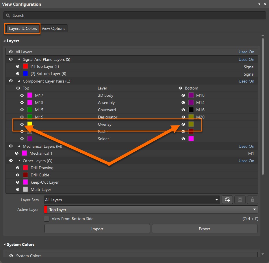 Once visible, carefully move these designators back into the main workspace area. By relocating the designator to a permissible area, you restore normal component movement functionality.
More generally, Altium restricts component placement and routing to the upper-right positive|positive quadrant. The PCB design space is bounded to the coordinates between (0,0) and (100000mil,100000mil) or 100x100 inches or 2540x2540 mm. No objects are allowed beyond this bounding box. Some objects such as during dxf import, however, can end up outside this bounding limit.
To determine the current location of the absolute origin, you can use Edit » Jump » Absolute Origin, your cursor will jump to the original Absolute Origin. Everything you do should be above and to the right of this point.
To reset the Origin, use Edit » Origin » Reset. Then you can move all your current work into the upper right quadrant by using Ctrl+A to select everything, then use Edit » Move » Move Selection to get a cross-hair pointer, use this to click a reference point and then move the cross-hair to where you would like the reference point to go.
Then, after your board is well into the upper right quadrant, you can use the Edit » Origin » Set command to place a relative origin wherever it works best for you as your relative (0,0) location.
Alternatively, if you want to move objects already outside the limit one by one, you can use the PCB List panel to locate them and type valid positive coordinates, since you will not be able to do so by click-&-drag mouse operation,
Tip: Placing a horizontal/vertical guides through the absolute origin (Place » Work Guides » Place Horizontal/Vertical Guide, followed by keyboard shortcut J and A to jump to the origin) would serve as visual cues thereafter indicating anything to the bottom/left of these guide lines need to be moved upward or to the right.
https://www.altium.com/documentation/altium-designer/pcb-working-with-grids-guides#!snap-guides
When guides are no longer needed, they can be disabled or deleted in Properties panel, under Guide Manager section.

Guide lines (and grid lines) will only show if the box is checked (default) for "Show Grid" in the General Settings region on the View Options tab of the View Configuration panel.