Variants are created and configured in the Variant Management dialog. To open the dialog, select Variants from the Project menu (shortcut: C, V) or right-click on the project name in the Projects panel then select Variants.
The dialog can also be accessed by right-clicking on a placed component in the schematic editor, then selecting Part Actions » Variants. In this case, the dialog will be populated with the parts that are currently selected in the schematic editor.
The Variant Management dialog is available when the UI.ModernVariantsManager option is disabled in the Advanced Settings dialog. When the UI.ModernVariantsManager option is enabled, the Variant Manager is used for creating and configuring design variants.
The dialog has two main regions:
-
The upper Components for project region, which lists all of the components in the base design, and if applicable, columns for the applied Variants.
-
The lower Component Parameters region, which details all of the parameters of the component(s) currently selected in the upper region, and if applicable, columns for the applied Variants.
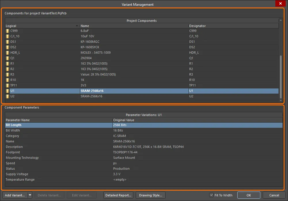
Variants are created and configured in the Variant Management dialog.
Options and Controls of the Variant Management Dialog
Components
Double-click on a component or right-click then select the Cross Probe option to jump to that component on the schematic.
-
Variant of – after a new variant is added, a dedicated column appears to the right of Project Components. The name given the new variant appears as the title and the Component Variation column lists any variations for each component. Once the variant has been created, you can configure the state of each component. This is done by clicking the component cell in the new column to reveal  or by right-clicking to access the context menu commands. When
  is clicked, the Edit Component Variation dialog opens and presents three choices:
-
Fitted – the original component as used in the base design is also fitted/used in this variant of that design. For a newly added variant, all components are Fitted by default and the cell is empty. Note that individual parameters can also be varied for a Fitted component – type in the new parameter value. Varied parameters are shown in bold.
-
Not Fitted – the original component as used in the base design is not fitted/used in this variant of that design. For a Not Fitted component, the cell displays the text Not Fitted.
-
Alternate Part – this option gives access to browsing and selecting the alternate part. Once chosen, the cell displays the alternate part's Library Link or server component, whichever was chosen. The lower region of the dialog will display all of the parameters in the alternate part.
To make a variant active in the dialog, either click on that variant's name in the column header or click in any of that variant's cells.
When you configure variations in this dialog, the settings are saved in the project file. This includes the Not Fitted state, local parameter variations to a Fitted component, and the parameter values of Alternate Parts. The Alternate Parts are stored in the file <ProjectName>.PrjPcbVariants.
To change the order the variants are listed, click and hold on the column heading, then drag that column to a new location. Use this in combination with the Fit to Width checkbox to position and size the variant of interest in your preferred working location.
-
Right-click Commands – the following commands are available on the Components region's right-click menu:
-
Columns – click to see/hide columns that are not needed. Toggle the visibility of any column.
-
Edit Selected – make changes to the selected component.
-
Set Selected As – click to change to Fitted, Not Fitted, or Alternate.
-
Only Show Varied Components – click to show varied components in the listing.
-
Filter – click to filter components listed by Show Fitted with Varied Parameters, Show Not Fitted, or Show Alternate.
If you have been experimenting with the Filter options and have applied different filters, you may need to reset the filter before attempting another update. To do this, disable the Only Show Varied Components option to clear the filter system, then re-apply it and clear the Filter options as required.
-
Cut – click to delete the selected variant.
-
Copy – click to make a copy of the selected item.
-
Report – click to open the Report Preview dialog to create a printout of the Components region.
-
Save All – click to open a dialog to save a listing of all project components to another location as a tab formatted text file.
-
Save Selected – click to open a dialog to save a listing of all selected project components to another location as a tab formatted text file.
-
Select All – click to select all cells.
-
Select Column – click to select the current column.
-
Invert Selection – click to select all components other than those that are currently selected.
-
Cross Probe – click to show the selected component's location on the schematic.
Standard Windows multi-select techniques are supported; use these to select and configure multiple components simultaneously.
Component Parameters
Each component in the dialog can have Parameter Variations. The Parameter Name and its Original Value are listed along with New Value listings for columns representing variants that have been added. The New Value that appears is a copy of the base design component value until changes are made. Right-click in a cell to access the range of parameter commands from the pop-up menu. The menu offers the following options:
-
Edit Selected – click to change New Value of the selected variant cell.
-
Reset Selected – click to restore New Value back to original value.
-
Reset All – click to restore all New Value cells to their original value, regardless of current selection.
Edit Selected, Reset Selected, and Reset All are available only when right-clicking in an added variant column.
-
Update Values From Library – click to bring any parameter changes made to a library component that has been used as an Alternate Part into the variant definitions. Note that this updates the parameters only and not the component itself.
-
Only Show Varied Values – click to show only those values that have been varied from the original values.
-
Cut – click to delete cell contents. A Confirm window opens for confirmation before deletion occurs.
Cut is available only when right-click is done in the Component Variation and New Value columns.
-
Copy – click to make a copy of the selected item.
-
Report – click to open the Report Preview dialog to create a printout of the Component Parameters region.
-
Save All – click to open a dialog to save all parameters for the selected component to a formatted text file in another location.
-
Save Selected – click to open a dialog to save all selected parameters to a formatted text file in another location.
-
Select All – click to select all cells.
-
Select Column – click to select the current column.
-
Invert Selection – click to select all parameters other than those that are currently selected.
Additional Controls
-
Add Variant – click to open the Edit Project Variant dialog to create a new variant of the base design. Use this dialog to add, edit or remove a variant and specify any required variant-level parametric data. This button includes a drop-down that is used to access the Make a copy of the Selected Variant command. Copying is particularly useful when you need to define a number of variants that are very similar.
-
Delete Variant – click to delete selected variant(s). A dialog opens for confirmation before deletion occurs.
-
Edit Variant – click to open Edit Project Variant dialog to edit a variant.
-
Detailed Report – click to open the Variant Report dialog to generate a detailed variant report in HTML format.
-
Drawing Style – click to access the Variant Options dialog in which you can define how non-fitted components and varied parameters will appear, both in the compiled document view of the schematic and in schematic prints. You can also define the appearance for these components in PCB assembly drawings.
-
Fit to Width – check this option to automatically adjust the width of the columns based on the content.
Double-click on a component in the Variant Management dialog to jump to that component on the schematic or select Cross Probe from the right-click context menu.
Creating a New Variant
Click the  button in the Variant Management dialog to create a new variant of the base design. The Edit Project Variant dialog will open.

At the very minimum, enter a name for the variant in the Description field, which, by default, will have the entry Variant of <ProjectName>.
If fabrication variants need to be generated from the design, enable the Allow variation of fabrication outputs option in the Edit Project Variant dialog. If paste mask outputs need to be generated for a design that includes variants with 'Not Fitted' components, enable the Allow variation for paste mask option. These components will no longer have paste mask included on their pads.
You can choose if an alternate part needs its symbol to be changed on a schematic or its footprint to be added to the PCB using the following options in the Edit Project Variant dialog:
-
Do not overwrite schematic symbol – when enabled, non-varied symbols will be used for components for which alternate parts are selected in the variant.
Note that this option affects only the representation of the symbol on the schematic sheet. The alternate part symbol is considered when the design connectivity model is built. Therefore, the base and aternate components need to pin-compatible even is the option is enabled. Refer to the Choosing an Alternate Part section to learn more about pin compatibility.
-
Do not overwrite PCB footprint – when enabled, non-varied footprints will be used for components for which alternate parts are selected in the variant. A footprint of an alternative part applied to a variant will not be transferred to the PCB as part of the PCB update (an ECO to add the footprint to the PCB will not be generated).
Irrespective of whether these two parameters are enabled or not, parameters for the chosen alternate are faithfully presented in the ActiveBOM.
You can also define parameters for the variant. For details on how to do this and how variant-level parameters fit into the parametric hierarchy within Altium Designer, see Working with Variant Parameters.
With the variant defined as required, click OK. An additional column will then appear on the right of the Variant Management dialog, with the new Variant name as the column title. All the cells will be empty, where an empty cell indicates that this component is Fitted and unchanged from the base design. The components can now be configured for the new variant. The image below shows a project that has had two variants created, BGA and TSOP.
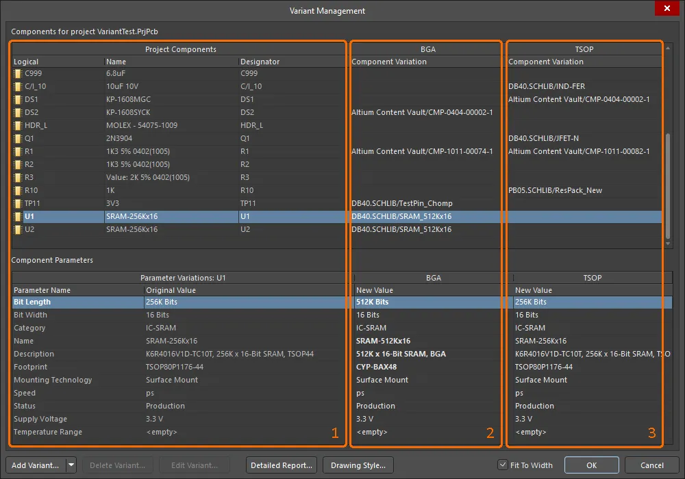
Region 1 details the components in the base design, region 2 details the components in the BGA variant, and region 3 details the components in the TSOP variant.
To make a variant the active selection, click its variant name in the column header, or click in any of that variant's cells.
The Variant Management dialog includes a number of interface features that assist the display of useful information. These are configured via the right-click context menu.

Useful commands include:
-
Columns:
-
Hierarchy Path column – shows the location of the component in the design hierarchy.
-
Original Library Link column – details where the base component was sourced from.
-
Set Selected As – submenu used to choose the type of variation (Fitted, Not Fitted, Alternate). Can be used instead of clicking the
 control in the component cell. Only available when you right-click on a Variant's component cell.
-
Only Show Varied Parameters – only display components that have some form of variation applied, in the Variant Management dialog.
-
Filter – submenu that gives control of which types of variations are displayed in the Variant Management dialog (Varied Parameters, Not Fitted, Alternate). Works well in combination with the Only Show Varied Parameters command.
Varied parameters – a parameter that is varied from the base design is shown in bold in the Component Parameters area of the Variant Management dialog, making it easy to visually identify.
Defining Component Variations
Once the Variant itself has been created, the state of each component is ready to be varied. This can be done by clicking on a component cell in the variant column to reveal the  control, or by right-clicking on the cell and choosing the required entry from the Set Selected As context sub-menu.
The  control opens the Edit Component Variation dialog.
The Edit Component Variation dialog can also be accessed from the compiled tab of a schematic by right-clicking on a component with a defined variant, then choosing Part Actions » Choose Alternate Part.

Three choices are offered:
-
Fitted – The original component as used in the base design is also fitted/used in this variant of that design. For a newly added variant, all components are fitted by default, and the cells for these fitted components are empty. Note that individual parameters can also be varied for a fitted component, by simply typing in a new parameter value in the dialog's Component Parameters region for that Variant.
-
Not Fitted – The original component as used in the base design is not fitted/used in this variant of that design. For a Not Fitted component status, the cell displays the text Not Fitted and the dialog's lower Component Parameters region will be blank.
-
Alternate Part – This option allows a different (alternate) part to be selected. The dialog will expand to include controls to browse and locate the required replacement component. Once that part is chosen, the cell displays the alternate part's source Link. The lower Component Parameters region of the dialog will display all of the parameters in the alternate part. See the next section for more information.
Standard Windows multi-select techniques are supported. Use these to select and configure multiple components simultaneously.
Choosing an Alternate Part
When the Alternate Part option is selected, the Edit Component Variation dialog expands to show the base parameters of the existing part. Use the  button to browse and locate the required alternate part component in the Replace Component dialog – a modal dialog version of the Components panel. All of Altium Designer's component storage models are supported, such as independent libraries, database libraries, as well as Workspace Library components (as shown in the example below).
After selecting an alternate part, the software checks for pin compatibility between the selected alternate component and the original base design component. To be pin-compatible, the alternate must have the same number of pins as the original component, and those pins must be identical in their location and electrical type. The graphical primitives used in the symbols for the two components are not required to match. If the software detects that the alternate component is not pin-compatible, a Confirm dialog must be dismissed before the replacement is accepted. In this case, you need to be mindful of the potential impact on the wiring, and that an error violation may be encountered as the design is validated (Project » Validate <project name>).
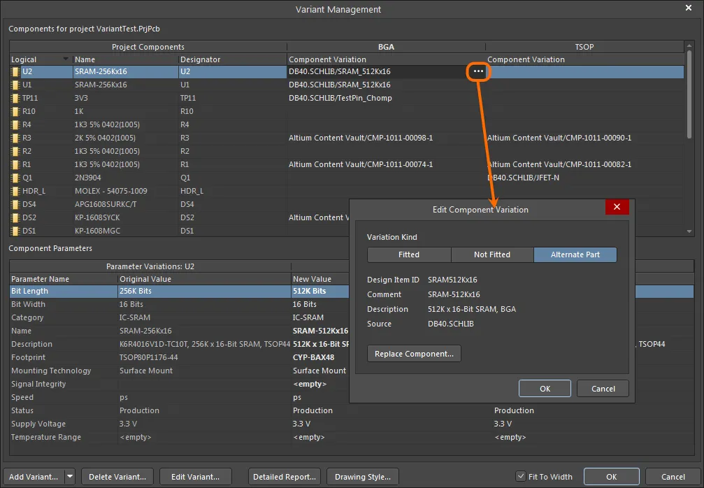
An example of an Alternate Part variation.
The newly applied alternative component can be checked back in the design space – refer to the Working with Variants in the Design page to learn more.
You can choose an alternate part with no changes to a symbol on a schematic or needing to add a footprint to the PCB. In the Edit Project Variant dialog, enable the Do not overwrite schematic symbol and/or Do not overwrite PCB footprint options as needed. When the latter is enabled, a footprint of an alternative component applied to a variant will not be transferred to the PCB as part of the PCB update (an ECO to add the footprint to the PCB will not be generated). Parameters for the chosen alternate are faithfully presented in the ActiveBOM.
Variants When a DbLink File is Used
Altium Designer supports several ways of storing and working with components, including the use of a DBLink file with the project. A DBLink file is an interface between the components on the schematic and a company database.
Rather than just creating a reference from each component to a specific database record (as is typically done when you place a component from a DBLib-type library), the DBLink model relies on the designer initiating a query action based on one or more component parameters. The software then searches the database for a record with fields that contain matching values, and when a match occurs, other field values from that record (such as the Part Number) can be returned to the Altium Designer component. The component parameter-to-database field mapping is defined in the DBLink document, as is the target database.
► Learn more about Database Libraries
In a design that does not use Variants, the query action is performed via the Update Parameters from Database command, and can also be performed during BOM generation by enabling the Include Parameters from Database option (see below), to extract BOM-specific component data, such as price.
For a design that includes Variants, the parameters used to query the database are varied in the Variant Management dialog. Since those parameter values only exist in the Variant Management dialog, the Update Parameters from Database command is not used to retrieve database information – instead the parameters are extracted from the database when the BOM is being generated.
Display of Variant Management Dialog Data
The Variant Management dialog includes features to help control the amount of data displayed, which is particularly useful when working on a large design.
-
To remove columns that are not of interest, right-click in the upper part of the dialog and use the Columns option in the context menu to toggle the visibility of any column.
-
To display only those components being varied, right-click in the upper part of the dialog and select Only Show Varied Components option from the context menu.
-
When the Only Show Varied Components mode has been selected, right-click again and configure the Filter options. In the image shown below, the Filter has been configured to display only those components that use Alternate Parts.
-
To change the order of the listed Variants, select and drag a variant column heading to a new location. Use this in combination with the Fit to Width checkbox to position and size the variant of interest.
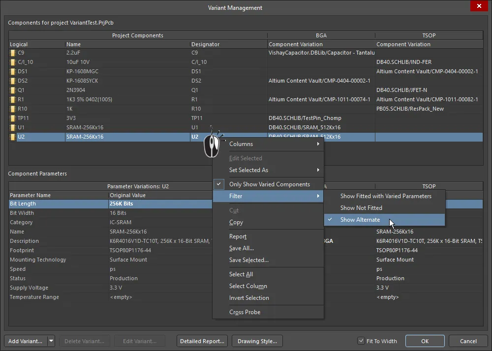
The Variant Management dialog, with columns hidden and a filter applied to only show components that use an Alternate Part.
Resetting and Updating Variant Data
Design variations set up in the Variant Management dialog are ultimately saved in the project file. This includes the Not Fitted state, local parameter variations to a Fitted component, and the parameter values of Alternate Parts. The actual Alternate Parts are stored in a [ProjectName].PrjPcbVariants file. The Variant Management dialog includes commands for resetting parameters and updating components, which helps to ensure that they are in sync with the source component libraries.
Updating a Varied Parameter
Parameters modified locally in the Variant Management dialog can be restored to their original value by right-clicking on the modified parameter (shown in bold) in the Variant Parameter list, and then choosing Reset Selected from the context menu – as shown below. Note that multiple parameters can be selected at once then reset in a single action, or Reset All used to reset all parameters for that component.
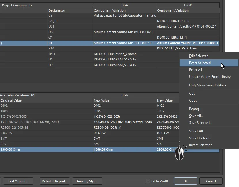
Modified parameter(s) can have their value(s) restored using the Reset Selected command.
Updating an Alternate Part Parameter
If a library component that is used as an Alternate Part has had parameters changed in the library, you can bring those changes directly into the variant definitions in your project by right-clicking in that Variant's Parameter list and selecting Update Values from Library from the menu (as shown below). Note that this updates the parameters; if you need to update the graphic, use the technique described below.
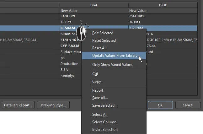
If an Alternate Part component has been modified in the library, use the Update Values from Library command to refresh the copy used in the project.
Following the Update Values from Library command, browse to and locate the component in the source library via the Browse Libraries dialog and click OK to open the Update Project Variants From Library dialog. Select/deselect the Parameters from Library Component and Variants to Update, then click OK to complete the update process.
If the component selected for a parameter update is a Workspace component, a basic modal dialog version of the
Components panel will be opened rather than the
Browse Libraries dialog. Browse or Search to locate the component, click
OK to open the
Update Project Variants From Library dialog then select the desired parameters for updating, as described here.
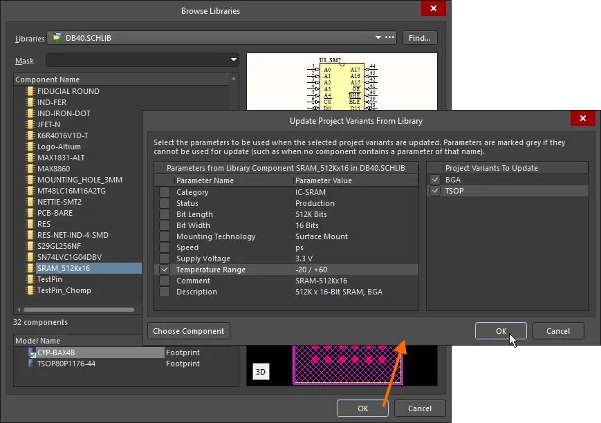
Updating a varied component from the source library. Here you configure which parameters are updated, and to which variant the updates are applied.
Options and Controls of the Browse Libraries Dialog
-
Libraries - displays the current library. Use the drop-down arrow to access a list of available libraries then select the desired target library. Click the
 button to open the Available File-based Libraries dialog in which you can add or remove libraries.
-
Find - click to open the File-based Libraries Search dialog to locate additional libraries.
-
Mask - enter the desired key words to mask results in the Component Name list. The drop-down lists previously used key words.
Upper Grid
-
Component Name - displays the name of the component.
-
Library - displays in which library the component is located.
-
Description - a brief description of the component.
-
Footprint - displays the associated footprint (if any).
-
<nn> components - displays the total number (nn) of components.
Lower Grid
-
Model Name - displays the model name of a component currently selected in the upper grid.
-
Type - displays the model type of a component currently selected in the upper grid.
Preview Windows
-
Upper Window - displays the schematic symbol of the component currently selected in the upper grid.
-
Lower Window - displays the footprint of the component currently selected in the upper grid.
-
2D/3D - use to toggle between 2D and 3D preview images.
Options and Controls of the Update Project Variants From Library Dialog
-
Parameters from Grid - lists of all parameters and their values of the selected component. Check the box to select the parameters to be updated. Parameters are grayed out if they cannot be used to update (e.g., when no components contain a parameter of that name).
-
Project Variants To Update Grid - a list of all variants that currently exist in the project. Check the box to select the variants to be updated.
-
Choose Component - click to open a dialog in which you can search for components.
All parameters are listed on the left of the Update Project Variants From Library dialog – if required, any parameter can be deselected to exclude it from the update process. On the right of the dialog, the target Project Variant can be changed (Project Variant To Update). This will default to select the Variant that was selected when the Update Values from Library command was activated.
Note that this parameter update process brings parameter values directly from the library into the Variant Management dialog, and does not update the copy of the component that is stored in the [ProjectName].PrjPcbVariants file. If you later perform one of the Reset commands to reset parameter values, which retrieves values from the PrjPcbVariants file, it may revert a parameter value to an earlier value and overwrite any current changes. To ensure that this cannot happen, update the component in the PrjPcbVariants file using the process described below.
Completely Updating an Alternate Part
If the source component for an Alternate Part has been edited in its library, it can be updated in the design by running the Update from Library dialog.
Launched from the Tools menu in the schematic editor, the dialog includes an option to Include Variants. When this option is enabled, the component list will expand to include any components that have been used as Alternate Parts. Check the components in the list to be updated, and then complete the Wizard to update the required parts from the source.
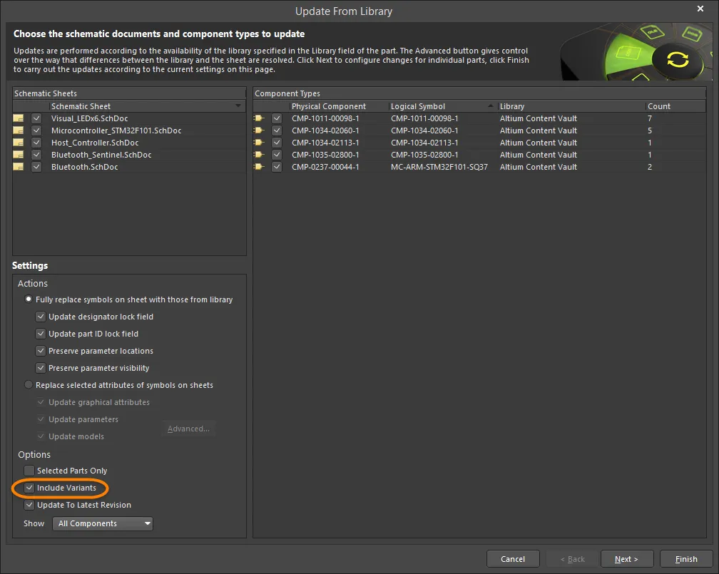
To fully update an Alternate Part, including its graphic, enable the Include Variants checkbox and enable the part to be updated.
If there have been changes made to library components used in the base design, these are also updated in the usual way:
-
via the Schematic editor Tools » Update from Library command
-
or the Schematic Library editor Tools » Update Schematics command.
Change Multiple Parameters for Multiple Components
The Variant Management dialog supports multi-select, which means that any number of components can be selected simultaneously in the upper (Component) part of the dialog, and then updates performed on any number of parameters selected in the lower (Parameters) part of the dialog. The dialog also offers Filters (via the right-click context menu), to further refine the selection and the displayed data.
By way of example, to reset the manually-varied parameters for all components, in all variants:
-
In the upper (Component) part of the dialog, use the Only Show Varied Components right-click menu option in combination with the right-click Filter options to only Show Fitted with Varied Parameters. The component list should now display only those components that have manually varied parameters.
-
Right-click in the component list and choose Select All from the context menu. All components currently displayed in the upper part of the dialog will be selected.
-
Then right-click in the lower (Parameters) part of the dialog and choose Select All from that context menu. All parameters for all components will now be selected. Note that the Select Column command could have been chosen instead, which would allow an action (such as Reset) to be applied to the components in a specific Variant (column).
-
Right-click again in the parameters list and choose Reset Selected from the context menu. Hover the cursor over the image below to show steps 2, 3 and 4.
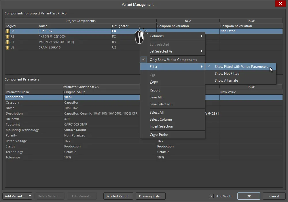
Resetting all manually varied parameters, for all components, in all variants. Hover the cursor over the image to show steps 2, 3 and 4.
If you have been experimenting with the Filter options and have applied different filters, you may need to reset the filter before attempting another update. To do this, disable the Only Show Varied Components option to clear the filter system, then re-apply it and clear the Filter options as required.
Working with Variant Parameters
Altium Designer supports Parameters at various levels of a project. For example, document-level parameters can be added to each schematic sheet in the Parameters tab of the Schematic editor Properties panel (available when nothing is selected). Project-level parameters can also be added to a project on the Parameters tab of the Project Options dialog (Project » Options).
Further to this, parameters can also be added to a Variant via the Edit Project Variant dialog. In the Variant Management dialog, select the variant column and click the Edit Variant button to open this dialog. To add a new parameter, click the Add button. Use the Parameter Properties dialog that opens to enter the Name and set the Value of the new parameter then click OK. The new parameter is now displayed in the Edit Project Variant dialog.

Parameters included at various levels in a project exist in a hierarchy, which means you can, in fact, create a parameter with the same name at different levels in the project, where each has a different value. Altium Designer resolves this situation using priorities, in the following way:
-
Variant (highest priority)
-
Schematic document
-
Project
This arrangement means that the parameter value defined in a schematic document overrides the value defined in the Project options, and the parameter's value defined in a Variant overrides the value defined in the schematic document. Note that schematic-level parameters are not available on the PCB or in the BOM – for these types of output, project or variant parameters should be used.
In the images below, a Parameter called ProjectTitle has been defined for the project, and also for each variant. The animation shows the behavior on the PCB as the Variants selector is used to show the base design, then each variant.
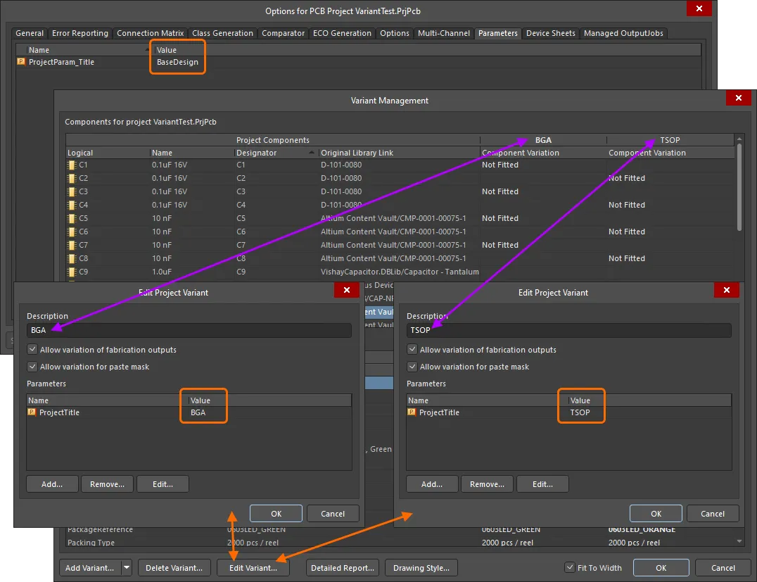
A ProjectTitle parameter added to the project (via the Project Options dialog) has also been added to each design Variant, but with a different Value in each case.
 A special string
 .ProjectTitle has been placed on the PCB overlay, which is automatically linked to project and variant parameters of the same name.
Generating a Variant Report
The Variant Report dialog accessed by clicking the Detailed Report button at the bottom of the Variant Management dialog allows you to configure and generate a detailed HTML-formatted report of the defined project variants.
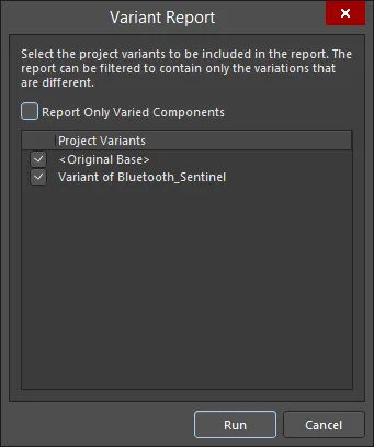
The Variant Report dialog
Options and Controls of the Variant Report Dialog
-
Report Only Varied Components - use this option to determine the exact information featured in the report:
-
Full Non-Varied Information (option disabled) - all components are listed, showing their inclusion state in each enabled variant. For each component, all parameters and their values are listed.
-
Full Varied Information (option enabled) - only those components that vary in some way between enabled variants are listed, showing their inclusion state in each variant. For each component, only those parameters that vary in some way between variants are listed, along with their values.
-
Project Variants - this region lists the original base design (<Original Base>) and all defined variants. The generated report could compare one specific variant against the base design, compare one variant against another, or compare all variants against the base design. By default, all defined variants, as well as the original base design, will be enabled for inclusion into the report. Use the associated checkbox to include/exclude entities as required.
-
Run - click this button to generate the report. The report will be created and opened as the active document within the main design window.
Variant Errors
Variant settings are stored in the project file (*.PrjPcb), and this data is read, analyzed and loaded into the Variant Management dialog when that dialog is opened. If issues are detected when the data loads, such as any mismatches between component designators or component UIDs, an Information dialog will open to outline the problem.

Resolve designator and UID mismatches before continuing with the design process.
Component UID mismatches are automatically resolved, and these corrections will be retained when the project is saved. Duplicate designators must be corrected at the schematic level. To resolve these, validate the project (Project » Validate <project name>) and check the Messages panel for warning/error details.