A Text object places a single-line string or multi-line text frame on the selected layer in a variety of display styles and formats including popular barcoding standards. It can be user-defined text or a special type of string, referred to as a special string that can be used to display board or system information or the value of user parameters on the board. The text frame is a re-sizeable rectangular area that can contain multiple lines of text and can automatically wrap and clip text to keep it within the bounds of the frame.
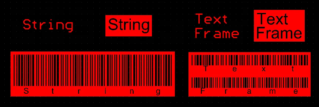
Placed Text objects
Text objects are available for placement in both PCB and PCB footprint editors by choosing the Place » String or Place » Text Frame command from the main menus. After launching the string placement command, the cursor will change to a cross-hair and you will enter text placement mode. A text object will appear floating on the cursor:
- Position the cursor then click or press Enter to place a text object.
- Continue placing further text objects or right-click or press Esc to exit placement mode.
Depending on the selected placement command (
Place » String or
Place » Text Frame), the Text object being placed will be in
String or
Frame mode that can be changed in the
Properties panel during or after placement.
Additional actions that can be performed during placement are:
- Press the Spacebar to rotate the text object counterclockwise or Shift+Spacebar for clockwise rotation. Rotation is in accordance with the value for the Rotation Step defined on the PCB Editor – General page of the Preferences dialog.
- Press the X or Y keys to mirror the text object along the X-axis or Y-axis.
- Press the L key to flip the text object to the other side of the board.
- Press the + and - keys (on the numeric keypad) to cycle forward and backward through all visible layers in the design to change placement layer quickly.
The graphical method of editing allows you to select a placed text object directly in the design space and change its location, rotation, orientation, and size.
When a text object is selected, the following editing handles are available:
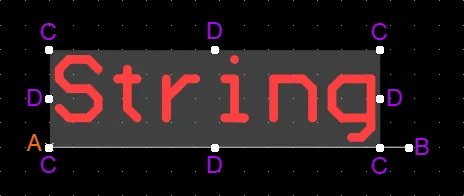
A selected Text
- Click and drag B to rotate the text object about its reference point A (denoted by the small x).
- Click and drag C to resize the text object's bounding box in the vertical and horizontal directions simultaneously.
- Click and drag D to resize the text object's bounding box in the vertical and horizontal directions separately.
- Click anywhere on the text object away from editing handles and drag to reposition it. While dragging, the comment can be rotated or mirrored:
- Press the Spacebar to rotate the text object counterclockwise or Shift+Spacebar for clockwise rotation. Rotation is in accordance with the value for the Rotation Step defined on the PCB Editor – General page of the Preferences dialog.
- Press the X or Y keys to mirror the text object along the X-axis or Y-axis.
- The default text for a newly-placed string object is String. Once placed (unless changed before or during placement), change this text as required using the text entry window when viewing the properties for the string through the Properties panel.
- The software provides the ability to place Text objects as barcode symbols directly onto a PCB on any layer, allowing barcodes to be easily imprinted on a PCB as part of the manufacturing process. To learn more about using a Text object as a barcode, see the Adding a Barcode section of the Including Barcodes & Logos page.
Special Strings
While text objects can be used to place user-defined text on the current PCB layer, it is not only user-defined text that can be placed. To assist in producing documentation, the concept of special strings is used. These act as placeholders for design, system or project information that is to be displayed on the PCB at the time of output generation.

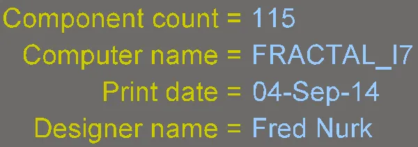
Examples of design, system, and design parameter special strings shown as source strings (the first image) and converted (the second image).
The special strings that are available in a PCB document come from a number of sources:
- A default set of predefined special strings are provided for use with new PCB documents.
- Custom special strings can be added by defining additional parameters at the project-level (these parameters are defined on the Parameters tab of the Project Options dialog) and at the variant-level (these parameters are defined in the Edit Project Variant dialog or in the Properties panel in its Variant mode in the Variant Manager).
- User Parameters added to components in the schematic domain are transferred via an ECO to become available to PCB components. If a special string that refers to a component parameter is added to a PCB footprint at the source library level, that string will be interpreted on the target mechanical layer or overlay when the PCB component is placed.
Notes about Using Special Strings
- A special string is denoted by the string starting with a . (dot) character (e.g.
.Layer_Name, .Net_Count, etc). If a string starts with ".", the entire string is treated as a 'special' string. This syntax is also used when referencing a user-parameter, the parameter name is preceeded by the "." (dot) character.
- To include more than one special string within a PCB text, enclose each special string within apostrophe ( ' ) characters; for example:
'.Pcb_File_Name_No_Path' '.Print_Date'.
- You can also use text, spaces and special characters between concatenated special strings, for example:
FileName= '.Pcb_File_Name_No_Path' : PrintDate = '.Print_Date'.
- Spaces and special characters can also be used within Project and Variant parameter names.
-
The values of some special strings can only be viewed when the relevant output is generated, including the .Legend, .Plot_File_Name, and .Printout_Name. Most special strings can be viewed on screen.
When generating documentation for a PCB project and releasing into a Workspace, there needs to be some way of indicating which Item and Revision the documentation relates to, as well as the configuration of the design project used in the release and any applicable driving variant. A set of special strings are available to manage this, including .PCBConfigurationName, .ItemAndRevision, and .VariantName. These special strings are not interpreted until the time the output is generated (unless viewing the PCB in 3D, which itself is considered an output). The information supplied by using these strings can be seen on generated output including Gerber/ODB++ files, Final Artwork prints, PCB prints, PCB 3D prints, PCB 3D Video, and Assembly drawings.
- Special strings are automatically converted for on-screen display. If the string cannot be converted either the value of the typed string, or a message will be displayed. For example, if the project is not under version control and the special string
.VersionControl_RevNumber is placed on the PCB, the message Not in Version Control will be displayed.
-
To assist in identifying special strings, the View Configuration panel includes a Special Strings option. When the option is enabled, any placed text objects that are formed from converted special strings will be superimposed (labeled) with the unconverted special string name.
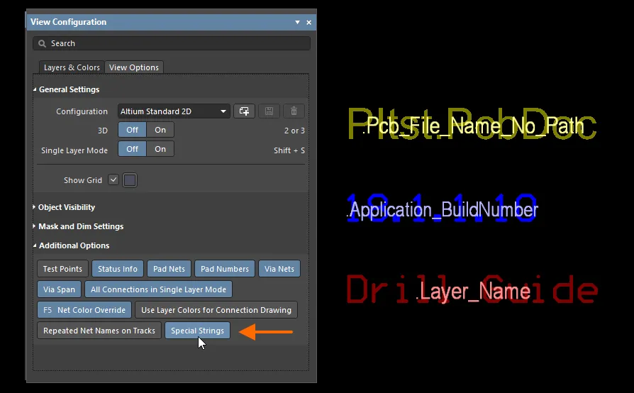
Placing a Special String
To use a special string on a PCB, place a text object then select one of the special string names from the Text field's drop-down (String mode) or the  drop-down (Frame mode) in the Properties panel.
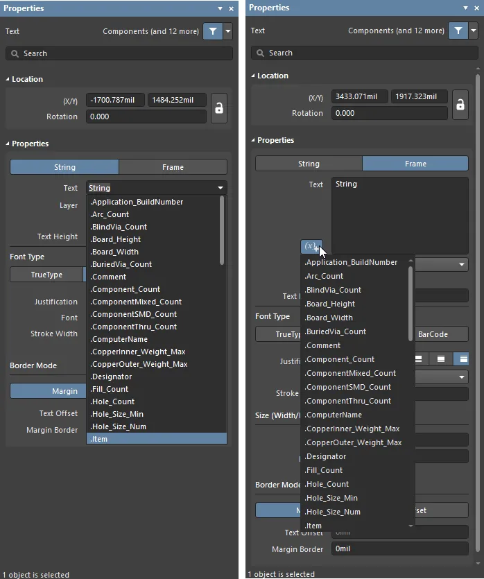
Accessing special strings for a placed string object.
The following are the predefined, system-based special strings available for use on a PCB document:
.Application_BuildNumber – the version of the software in which the PCB is currently loaded. When generating Gerber output, use this string to record the software build on which the design was created..Arc_Count – the number of arcs on the PCB..BlindVia_Count – the number of blind vias on the PCB..Board_Height – the vertical size of the PCB board..Board_Width – the horizontal size of the PCB board. .BuriedVia_Count – the number of buried vias on the PCB..Comment – the comment string for a component (placed on any layer in the library editor as part of the component footprint)..Component_Count – the number of components on the PCB..ComponentMixed_Count – the number of components with mixed pads on the PCB..ComponentSMD_Count – the number of components with SMD pads on the PCB..ComponentThru_Count – the number of components with thru-hole pads on the PCB..ComputerName – the name of the computer on which the software is installed and running..CopperInner_Weight_Max – the maximum weight of copper on inner layers..CopperOuter_Weight_Max – the maximum weight of copper on outer layers..Designator – the designator string for a component (placed on any layer in the library editor as part of the component footprint)..Fill_Count – the number of fills on the PCB..Hole_Count – the number of drill holes on the PCB..Hole_Size_Min – the minimum hole diameter on the PCB..Hole_Size_Num – the number of unique hole diameters on the PCB..Item – the Item that the generated data relates to (e.g., D-810-2000). The data will be used to build that item..ItemAndRevision – the item and specific revision of that Item that the generated data relates to in the format <Item ID>-<Revision ID> (e.g., D-810-2000-01.A.1). The data will be used to build that specific revision of that particular item..ItemRevision – the specific revision of the Item that the generated data relates to (e.g., 01.A.1). The data is stored in that Item Revision within the target server..ItemRevisionBase – the Base Level portion of an Item Revision's naming scheme (e.g., 1)..ItemRevisionLevel1 – the Level 1 portion of an Item Revision's naming scheme (e.g., A)..ItemRevisionLevel1AndBase – the Level 1 and Base Level portions of an Item Revision's naming scheme (e.g., A.1)..ItemRevisionLevel2 – the Level 2 portion of an Item Revision's naming scheme (e.g., 01)..ItemRevisionLevel2AndLevel1 – the Level 2 and Level 1 portions of an Item Revision's naming scheme (e.g., 01.A).
.Layer_Count – the number of copper layers on the PCB..Layer_Name – the name of the layer on which the string is placed..Legend – a symbol legend for mechanical drill plots. This string is only valid when placed on the Drill Drawing layer. Note: this is a legacy feature; place a Drill Table object for more detailed drill information..MicroVia_Count – the number of microvias on the PCB..ModifiedDate – the modified date stamp of the PCB; it is automatically populated. Example: 23/09/2015..ModifiedTime – the modified time stamp of the PCB; it is automatically populated..Net_Count – the total number of different nets on the PCB..Net_Names_On_Layer – the names of all nets on the specific layer. This string is only valid when placed on an internal plane layer..Pad_Count – the number of pads on the PCB..PadSMD_Count – the number of SMD pads on the PCB..PadThru_Count – the number of thru-hole pads on the PCB..Pattern – the names of the component footprints used on the PCB..Pcb_File_Name – the path and file name of the PCB document..Pcb_File_Name_No_Path – the file name of the PCB document..PCBConfigurationName – displays the name of the data set from which the output has been generated, as defined in the Project Releaser. Note that the names of the default Source, Fabrication and Assembly configurations cannot be edited (for example the Fabrication output will display Fabrication for the .PCBConfigurationName). User-defined Custom configurations will display the user-defined name when this special string is used (show image![]() ).
)..Plot_File_Name – for generated Gerber output, this string identifies the file name of the Gerber plot file. For printed output, it identifies the layer depicted within the output. For ODB++ output, it identifies the name of the parent folder in which the files are stored..Poly_Count – the number of polygons on the PCB (consisting of polygon pours, internal planes and split planes)..Print_Date – the date of printing/plotting..Print_Scale – the printing/plot scale factor..Print_Time – the time of printing/plotting..Printout_Name – the name of the printout..SlotHole_Count – the number of slotted holes on the PCB..SolderMask_Bottom – availability of bottom solder mask. If there is no bottom solder mask layer, the parameter will have the No mask value. If there is a bottom solder mask layer but its color is not defined, the parameter will have the No color value. If there is a bottom solder mask layer with its color defined, the parameter will show the color, either its name (Green, Black, Blue, Red, etc.) or its RGBA code (e.g., #FF0065FF)..SolderMask_Top – availability of top solder mask. If there is no top solder mask layer, the parameter will have the No mask value. If there is a top solder mask layer but its color is not defined, the parameter will have the No color value. If there is a top solder mask layer with its color defined, the parameter will show the color, either its name (Green, Black, Blue, Red, etc.) or its RGBA code (e.g., #FF0065FF)..SquareHole_Count – the number of square holes on the PCB..StackedVia_Count – the number of stacked vias on the PCB..String_Count – the number of strings on the PCB..Thru_Via_Count – the number of thru-hole vias on the PCB..Total_Thickness – the thickness of the board..Total_Thickness(Board Layer Stack) – the thickness of the board layer stack..Track_Count – the number of tracks on the PCB..VariantName – the variant of the design from which the output has been created..VersionControl_PrjFolderRevNumber – the current revision number of the project, which is incremented whenever a full commit of the project (i.e., including the project file) is performed. Version control must be used for this string to contain any information..VersionControl_ProjFolderRevNumber – the current revision number of the project, which is incremented whenever a full commit of the project (i.e., including the project file) is performed. Version control must be used for this string to contain any information..VersionControl_ProjFolderRevNumberShort – a short Git hash format (the first eight characters) of the Project. Version control must be used for this string to contain any information..VersionControl_RevNumber – the current revision number of the document. Version control must be used for this string to contain any information..VersionControl_RevNumberShort – a short Git hash format (the first eight characters) of the current revision number of the document. Version control must be used for this string to contain any information..Via_Count – the number of vias on the PCB.
The full list of special strings available will also include any derived from user-defined project-level parameters.
Text (String, Text Frame) Properties

The Text mode of the Properties
Location
The

icon to the right of this region must be displayed as

(unlocked) in order to access the below fields. Toggle the lock/unlock icon to change its lock status.
- (X/Y)
- X (first field) - the current X (horizontal) coordinate of the reference point of the text object, relative to the current design space origin. Edit to change the X position of the text object. The value can be entered in either metric or imperial; include the units when entering a value whose units are not the current default.
- Y (second field) - The current Y (vertical) coordinate of the reference point of the text object, relative to the current origin. Edit to change the Y position of the text object. The value can be entered in either metric or imperial; include the units when entering a value whose units are not the current default.
- Rotation - specify the rotation of the text object. The minimum angular resolution is 0.001 degrees.
Properties
Font Type
- TrueType - select to use fonts available on your PC (in the \Windows\Fonts folder). TrueType fonts offer full Unicode support. By default, the software links to a used TrueType font (they are not stored in the PCB file), which means the same font must be present on each PC to which the design is moved. Alternatively, embed used TrueType fonts in the PCB file using the options in the PCB Editor - True Type Fonts page of the Preferences dialog, where you can also select a Substitution Font to be used if a non-embedded Font is not available.
- Justification - use these controls to set the horizontal and vertical alignment of the text.
- Font - use the drop-down to select the desired TrueType font. Use the B (bold) and/or I (italic) options to add emphasis to the text as required.
- Inverted - enable to have the text displayed as inverted with control over the size of the border around the text (using the associated Width and Height fields that become available).
- Stroke
- Justification - use these controls to set the horizontal and vertical alignment of the text.
- Font - use the drop-down to select the desired Stroke font. Choices are:
Default - a simple vector font designed for pen plotting and vector photo plotting.Sans Serif - a complex font that will slow down vector output generation, such as Gerber.Serif - a complex font that will slow down vector output generation, such as Gerber.
- Stroke Width - displays the width of the stroke.
- BarCode - used to tag and identify PCBs, streamlining inventory tracking, for example, through the use of automated scan machines.
- Type - select one of the following bar code types:
- Code 39 - the US Department of Defense standard; often referred to as Code 3 of 9. It is also used in the automotive industry.
- Code 128 - the global trade identification standard; supports any of the ASCII 128 character set (all digits, character, and punctuation marks).
- Render Mode - choose a render mode for barcode display: Min Single Bar Width or Full BarCode Width.
- Full Width - specify the overall width of the bar code. This option is not available if Min Single Bar Width is selected.
- Full Height - specify the overall height of the bar code.
- Min Width - specify the minimum width of the bar code. This field is not available if Full BarCode Width is selected.
- Horizontal Margin - this field defines the size of the margin on the left and right edges.
- Vertical Margin - this field defines the size of the margin on the top and bottom edges.
- Font Name - use the drop-down to select the font.
- Show Text - enable to display the actual text string from which the barcode is derived (i.e. the string entered in the Text field).
- Inverted - when enabled, the bars are inverted and a border is added on all four sides.
- Border Mode
- Margin - click this button to enable the editing of the Margin Border option.
- Text Offset - the amount the designator is offset back from the edge/corner that it is justified against. This option has no effect when the Center justification mode is chosen. This option is not available for Margin.
- Offset - click this button to enable the editing of the Text Offset option.
- Margin Border - use to specify the size of the margin border surrounding the designator. This option is not available for Offset.
When the string is selected, a bounding box will appear, containing a small (x) on the bounding handle.