Parameters are general-purpose text strings that are child objects of a parent object. They identify and add additional information to that parent object and are accessed directly in the Properties panel when selected in a schematic sheet.
For example, schematic components make extensive use of parameters. General-purpose component parameters can be used for a variety of functions, including component detail, such as wattage, voltage, etc., supplier detail, including the supplier name and part number, library component design detail, such as the symbol's revision number and documentation detail, such as a URL that links to a component datasheet.
Parameters can also be defined at the schematic sheet (document) and project levels. Document-level parameters are used for defining fields such as the document title and number, while project-level parameters are ideal for defining fields such as the designer or the project name.
 Parameters are used for objects, documents and projects to add detailed information to the design. A component is shown in the above image.
Parameters are added or automatically included as properties of the parent object and are not placed independently like a text string. The types of available parameters can be broadly grouped as system and user parameters, where the latter is manually added.
Identifier and System Parameters
Objects placed in a schematic are automatically included with a range of key system parameters. These provide the base object information used by the system to distinguish the parent object's name, type and data source. The inherent system parameters for objects include, but are not limited to, the Comment, Description and Design Item ID (Library Reference) properties. Object system parameters are accessible in the General section of the Properties panel (under the General tab) when a parent object is selected ( ). When visible and selected in the design space, an individual parameter is accessible via the associated mode of the Properties panel, as outlined below(
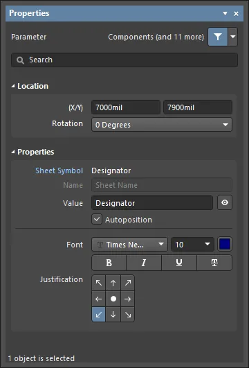 ).
).
Several system parameters cannot be made visible (and selected) on a schematic sheet and are, therefore, not available in the Properties panel. For component objects, these are Description, Design Item ID, Footprint, model references, and so on. Other system parameters that are not directly accessible in a schematic include document (sheet) and project parameters.
User Parameters
Parameters can be added to any of the following design objects.
| Component |
Add user-defined parameters in the Parameters region of the Properties panel when a component (part) object is selected or during component definition in the Schematic Library editor. System parameters such as designator and comment are always present for a component object, as outlined above. The Properties panel is accessed by double-clicking on an object or by right-clicking on an object and choosing Properties from the context menu. Select an object in the design space if the Properties panel is already active. |
| Part |
In the Parameters region of the Properties panel when a Part object is selected. |
| Pin |
On the Parameters tab of the Properties panel when a Pin object is selected within a *.SchLib file. |
| Port |
On the Parameters tab of the Properties panel when a Port object is selected. |
| Sheet Symbol |
On the Parameters tab of the Properties panel when a Sheet Symbol object is selected. |
| Document |
On the Parameters tab of the Properties panel when in Document Options mode (deselect all schematic objects or click in free space on the document sheet). A number of default parameters are automatically included in a new schematic sheet, as determined by the applied/default sheet template. |
| Project |
In the Project Options dialog (Project » Project Options). Project-level parameters are listed and added on the Parameters tab of the dialog. |
User parameters are available under the Parameters region of the Properties panel, or modal dialog when the parent object is selected. Parameters can be both added and edited. The exceptions are project parameters (via the Project Options dialog) and component pin parameters (via the Pin Properties or the modal view of the Pin dialog). When visible and selected in the design space, an individual parameter is accessible via the associated mode of the Properties panel or modal dialog, as outlined below.
. Second: An individual system parameter in the Properties panel.")
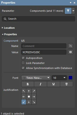 First: Component user parameters in the Properties panel (Parameters region). Second: An individual system parameter in the Properties panel.
Parameters added to a parent object during its placement (see above) will become the default parameters for further placements of that parent object unless the
Permanent option on the
Schematic – Default Primitives page of the
Preferences dialog is enabled for that object.
When this option is enabled, parameters added to the object being placed will also be added to subsequent objects placed during the same placement session, but not to any following placement sessions for that object.
Graphical Editing
Visible parameter strings can be edited graphically directly in the design space.
Click and drag a parameter to reposition it. To edit the parameter string in place:
-
Drag the mouse cursor around the parameter object while keeping the mouse button clicked.
-
Once selected, the object will be highlighted by a green border.
-
Select Enter to begin editing the text.
-
Once editing is complete, press Enter again or click away from the string to exit in-place editing mode.
 A parameter string can be selected and edited directly in the design space. Select the entire string to type over it.
Parameters that are visible and selectable in the design space may be dragged to a new location and rotated during the process. Click and drag the parameter string, use the Spacebar and Shift+Spacebar keys to rotate it in 90° increments, then click to confirm the new position/orientation.
See Parameter String Positioning below for information on component parameter Autopositioning and related Properties panel options.
Locked Parameters
A parameter that is the child of a Component Part can be locked, meaning its Name and Value strings are uneditable. This can be done by:
-
toggling the lock icon ( ) associated with its entry in the Parameters region in the Properties panel or modal dialog for its parent object, or
-
checking the Lock Parameter option in the Properties panel when the parameter is directly selected in the design space.
Once locked, the parameter string cannot be edited in the Properties panel, modal dialog (under Parameters for the parent object), or in the design space using in-place editing.
Component Parameters
Component parameters, the most obvious and frequently used schematic parameters, include additional sets of dedicated parameters and features that expand the ability to define component objects.
Defining Parameters in the Schematic Library
The child parameters of a parent component object can be defined in the component library source prior to placement in a schematic. The Properties panel is used to edit and add parameters to a component entry in the Schematic Library editor in the same manner as when working with parameters in the Schematic editor.
With a schematic component library document open, select a component entry in the SCH Library panel to access its parameter properties in the Properties panel.
 Access the properties of a library component by selecting its entry in the SCH Library panel.
A library component's Designator and Comment are not visible in the Schematic Library editor design space by default but can be enabled by checking the Show Comment/Designator option in the Library Options mode of the Properties panel (Tools » Document Options) – available when no objects are selected in the design space.
Parameters owned by a library component are defined and edited using the same process applied to placed schematic components. The Tab key may be used to create or edit parameters on the fly while an object is being placed in the design space. Parameters are accessed via the Properties panel or modal dialog, where the core system parameters are available under the panel's General tab, and user parameters are added/edited under the panel's Parameters drop-down.
To add a parameter to a component pin, for example, select the
Pin object in the design space and then the
Parameters drop-down in the
Properties panel or modal dialog. Click the
Add button to insert a new parameter Name/Value pair in the list. Parameters that are associated with the entire component are added as described above.
The Designator Parameter
In the Schematic Library editor, a component Designator parameter is typically given a suitable prefix followed by a question mark. When the component is placed in a schematic from the library, the question mark is detected by the Schematic editor's Annotation tool and replaced with a suitable numeric suffix during project annotation.
The Schematic editor also includes a simple auto-increment feature for the designator that can be used during the placement of multiple instances of the same part. To use this, press Tab while the first component is floating on the cursor to pause the placement, and then enter a suitable designator in the Properties panel; for example R1. Subsequent components will then be designated R2, R3, etc.
When placing multi-part components and the initial designator is assigned in this way, a part suffix will automatically be added, for example U3A, U3B, etc. If the initial designator is not assigned, all parts will have the same suffix. This can be resolved by the Schematic editor's annotation feature. The part suffix can be alpha or numeric, as specified by the Alpha Numeric Suffix option in the Schematic - General page of the Preferences dialog.
Parameter String Positioning
The default behavior of a component parameter string is to autoposition it (i.e. maintain orientation) when a component is rotated during or after placement. If this behavior is not required, turn off the Autoposition option for the component parameter entry under the Parameters region in the Properties panel. To access the option, select the parameter in the list then click Other. Note that during component placement, the Spacebar and Shift+Spacebar keys are used for rotation. A placed component object can be rotated via the Rotation menu in the Location region of the Properties panel or by selecting the component then pressing Spacebar or Shift+Spacebar.
Click and drag a visible parameter to manually reposition it on the schematic; the standard orientation shortcut keys will apply. If the Autoposition option is disabled for that parameter and the Mark Manual Parameters option is enabled in the Schematic - Graphical Editing page of the Preferences dialog, parameters that are manually moved will be identified by a dot on the lower left corner of their selection box.
Special Purpose Component Parameters
Special purpose component parameters are available for linking to related URL targets or file-based documentation. For a selected component, these are added by clicking Add in the Parameters region of the Properties panel then selecting Link from the drop-down, or under the Parameters tab for dedicated help links that are activated using the F1 key.
Link Parameters
The links feature enables the definition and presentation of named links to any number of reference URLs or documents.
To add a reference link for a component, select the component in the design space, then click Links under the Parameters region of the Properties panel. Select Link from the Add drop-down menu at the bottom of the Parameters region. Enter the link Name and Value (target URL or file path) in the grid. The link is then accessible by right-clicking on the component in the design space and selecting the link <name> from the References sub-menu.


The component links, as presented in the panel and design space, are internally based on Name/Value pairs in the format of ComponentLinknDescription/ComponentLinknURL (where n is the number of the link in the list, based on the order of creation). See the Parameter Table Editor entry for that component to see more detail.
The HelpURL Parameter
Similar to the link parameter, the HelpURL parameter allows the definition of a link from a component to an external document, such as a PDF, or web page URL. When added as a component parameter, the link is activated when the F1 key is pressed over the component on the schematic sheet or when the component is selected in the Libraries panel. Note that this action will override the normal F1 key feature, which links to the relevant page in the Altium online documentation.
The Help link is added as a user parameter in the Properties panel when a component is selected in the design space. Click Parameters under the Parameters region of the Properties panel, then select Parameter from the Add drop-down menu at the bottom of the Parameters region. Enter "HelpURL" as the parameter Name and the target path/URL as the parameter Value.

When specifying the value for the parameter, it can be a URL, an absolute path to a document, or just the document name. When F1 is pressed with the cursor hovering over the placed component object, or the References » Help option is used from the right-click menu, a search for the Help reference is conducted as follows:
-
If a path is specified, this location is searched first.
-
If the document cannot be found at this location, or if no path is specified, the
\Help folder of the software installation is searched.
-
If the target is a URL, the web page will be opened in the software's internal browser or an external browser, depending on the state of the Open internet links in external Web browser option on the System - View page of the Preferences dialog.
Indirection - A Parameter as a String Value
Most component parameters can be displayed on a schematic sheet by enabling the visibility icon ( ) (where available) in the Properties panel. Identifier and system parameters are available under the panel’s General tab, and user parameters are accessed in the panel’s Parameters region.
Other parameters, however, such as document and project parameters, cannot be directly displayed on the schematic sheet but may be inserted in a standard text object using a technique known as String Indirection. Indirection is where the Value entry for a string object is the name of an available parameter (such as a document or project parameter) preceded by an equals sign, for example, =Title.
The software automatically detects such strings and checks for an available parameter name that matches the value entry of the placed text object. The example of Title is found as a document parameter, causing the text string to interpret and display the title parameter value, for example, MyDocument. A parameter name may be directed to a selected text string value by in-place editing (i.e. typing =Title), or as a more informative approach, by using the Text drop-down menu in the Properties panel to select from the available parameter strings.

Special Strings
Parameter strings that are available as indirect strings (see above) are known as special strings. The value presented by these strings is actively inferred from templates or system and source data, so, for example, the special string =Time will detect and show the current system time, and =DocumentName will show the current schematic document file name (e.g., MySchematic.SchDoc).
There is a large number of predefined special strings available. Refer to the Working with Text Objects on a Schematic page to learn more about these special strings. Any user-defined document or project parameter can also be used as a special string and be 'indirected' to a text string on the schematic sheet.
Indirected strings are always interpreted and displayed during output generation, such as printing the schematic sheets. Many are also interpreted and displayed directly on screen.
Special strings are used to define fields in a title block, where the string indirection feature ensures the correct information for the active schematic is extracted from the document parameters and displayed accordingly.
Parameters have a hierarchy, which means you can create a parameter with the same name at different levels of the project, each having different values. For a component parameter, Altium Designer resolves this in the following way:
-
Component parameter (highest priority)
-
Variant
-
Schematic document
-
Sheet symbol (to see the value of the parameter of the sheet symbol above, select the Compiled tab at the bottom of the design space)
-
Project

Most of this panel's options/controls are straightforward and require no further explanation. One that does is described below.
-
Allow Synchronization with Database (Preferences dialog only) - enable to synchronize with the database. This option is used to control if the comment can be updated. By default, these options are enabled to always allow synchronization with the source library/database. You may disable this option to prevent that comment from being included in an update process.
Using the Parameter Manager
User-defined design attributes are added to your design using parameters. Parameters can be added and edited individually, or you can use the Parameter Table Editor dialog (Tools » Parameter Manager) to add and edit parameters across the entire design or across an entire library. These are parameters that are 'owned' by various object kinds in the source schematic documents of the active project or components in the active library. This provides a fast, efficient way to bring all parameters together in a single place for editing, with the ability to create an Engineering Change Order to implement any parameter changes you make directly to each affected 'owner' design object.
When you open the dialog, it gathers all parameter data for the entire design and presents it in a table-like grid. When the dialog is launched from a schematic, the Parameter Editor Options dialog opens. Select the type of parameters you want to be loaded into the Parameter Table Editor dialog. As an example, if you are working on component parameters, disable all options in the Include Parameters Owned By region except for Parts. You can further refine the scope of object inclusion using the drop-down field in the center of the dialog. Choose to include all objects, only objects with existing parameters, or only objects with existing parameters that are actually used.
Another example is if you are working on document parameters, enable only the Documents option. Note that the Exclude System Parameters option includes things like component model settings, document parameters that were defined in the template, and so on. Explore this option when you are more familiar with managing parameters.
If you want to edit the parameters for only specific objects in the design, select the objects as required and enable the Selected Objects Only option. Only objects in your selection will be included, provided the relevant object kind has been enabled in the Include Parameters Owned By region of the dialog.

After selecting the options needed, click OK to open the Parameter Table Editor dialog.

Most of the options/fields in the dialog are self-explanatory. Explanations for those that are not are defined below.
-
Remove Columns - click to remove columns. This option is only available for columns with static information.
-
Add Column - click to add a column. The Add Parameter dialog opens in which you can define the parameter name.
-
Reset Column Order - click to display the columns in alphabetical order.
-
Accept Changes (Create ECO) - in order to apply these changes to the components, an ECO (Engineering Change Order) must be generated. Click to open the Engineering Change Order dialog.
Right-click Menu
-
Revert - click to undo edits for the selected cells.
-
Add - click to add information to the selected cell. Use the resulting drop-down to select the desired information.
-
Rename Column - click open the Rename Existing Parameter dialog, where you may rename an existing parameter.
-
Remove Columns - click to delete the selected column.
-
Report - click to open the Report Preview dialog to generate a report.
-
Cross Probe - click to cross probe the selected object. The selected object will be highlighted in the schematic sheet.
The Object Type, Document and Identifier cannot be edited or deleted using the right-click menu.
Notes
-
You can drag and drop columns in the grid region to change the column display order. The new order is saved in the project file so that the order is remembered when the dialog is accessed again.
-
Parameters are prevented from being updated in the following ways:
-
At the individual component parameter level, enable the Lock Parameter option in the Component mode of the Properties panel (double-click a component to access). The Allow Synchronization With Database option is also used to control if the comment can be updated. By default, this option is enabled to always allow synchronization with the source library/database. You may disable this option to prevent the comment from being included in an update process.
-
At the database linkage level - the Field Mapping region of the relevant database linkage document (*.DbLink, *.DbLib, or *.SvnDbLib file) includes a number of options that control whether parameters can be updated including Update Values, Add to Design and Remove from Design.
Use this dialog to add, edit and remove parameters across the entire project. The dialog can be used to directly edit existing parameters in the project or to configure parameter updates from a linked database (linked via a DbLink, DbLib or SvnDbLib file). Note that these database library link-type files include options that control whether a parameter is to be updated or not. Changes are then implemented through an Engineering Change Order that you create from this dialog.
Adding a Parameter
To add a new parameter, click the button (or right-click anywhere in the main grid and choose the Add Column command from the context menu). The Add Parameter dialog will open. To just create the new parameter and not assign any values to any of the objects, enter the required name for it and click OK. If you want to add the parameter to all objects along with a specific value, enable the Add to all objects option, enter the required value, and then click OK. A column for the new parameter will be added at the end of the existing columns (to the far right of the listing).
Renaming a Parameter
To rename a parameter, right-click on a cell in the column you want to rename, then select Rename Column from the drop-down menu. The Rename Existing Parameter dialog opens. Enter the new name in the Enter the new name for the parameter field then click OK. Note that the column heading will have changed and now has a small blue triangle next to the name. This icon indicates that the value of this cell has changed.

The Rename Existing Parameter dialog
Adding a Parameter to Select Components
To add a parameter to components, select the cells in the Parameter Table Editor dialog editor using Shift+Click or Ctrl+Click key combinations, right-click, and then choose Add from the drop-down menu. After selecting Add, a small green plus symbol displays in each cell. This indicates that a new parameter has been added.

Now that the parameter has been added, you can define the component type for each component. The Parameter Table Editor dialog supports standard table editing shortcuts. You can press F2 to edit a cell, then press Enter to apply the edit. Multiple cells can be edited by selecting the cells, then right-click and choose Edit from the menu. Enter the new value, then press Enter to apply the edit to all selected cells.
Applying the Parameter Changes
The parameter edits that have just been completed are currently held in the Parameter Table Editor dialog and have not been applied to the components on the schematic sheets. To apply these changes to the components, you need to generate an ECO and then apply the ECO to the design. In the Parameter Table Editor dialog, click the Accept Changes (Create ECO) button. The Parameter Editor Table dialog will close, and the Engineering Change Order dialog will open.

Click the Validate Changes button to verify that the changes can be applied. If they are valid, a green check will be displayed in the Check column.

Click Execute Changes to apply the parameter changes to the components. Once the changes have been applied, close the Engineering Change Order dialog.
