Ansys CoDesigner
Due to the complexity of modern electronic products featuring high-speed and RF circuits, intensive communication between PCB and simulation engineers is required during the PCB design process, and this communication should be as clear and simple for both sides as possible. It is not sufficient to export a design changed by the PCB engineer or optimized by the simulation engineer and pass it to the other side – it should also be communicated what has been changed, which is usually done by email or verbally. This approach is imperfect because of the need to track all requests and compare the data manually to decide on design changes or to start a new analysis. These and other related challenges can be overcome by Ansys CoDesigner, an interface for transferring printed circuit board designs between the PCB design and simulation domains.
Supported Software
The following simulation platform and its versions are currently supported:
Ansys Electronics Desktop (AEDT) – version 2023 R1, 2023 R2, 2024 R1, 2024 R2
Installing and Configuring
To access the Ansys CoDesigner in Altium Designer, the Ansys CoDesigner software extension must be installed. This extension can be installed or removed manually.
For more information about managing extensions, refer to the Extending Your Installation page (Altium Designer Develop, Altium Designer Agile, Altium Designer).
To access the Ansys CoDesigner in Ansys Electronics Desktop, the Altium Link extension must be installed. The process is as follows:
-
Download and unzip the Altium Link extension archive. It can be obtained by contacting ansyscollaboration@altium.com (provide the AEDT version used).
-
Make sure the AEDT application is closed.
-
In the unzipped folder, locate the
install_altiumlink.batfile, right-click it and select Run as administrator. -
Open AEDT and select the Tools » Layout Links command from the main menus.
-
On the Config tab of the Layout Links dialog that opens, click the Add Link button, browse to the
\AnsysEM\<version>\Win64folder of the AEDT program files, and open thealtiumlink.dllfile. -
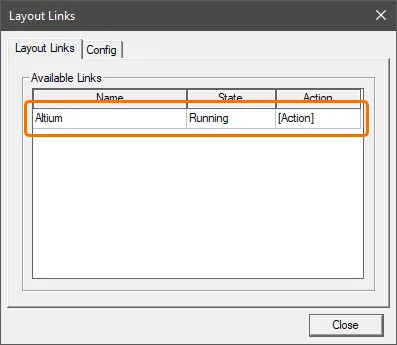
On the Layout Links tab of the Layout Links dialog, make sure the Altium link is listed and close the dialog.
How it Works
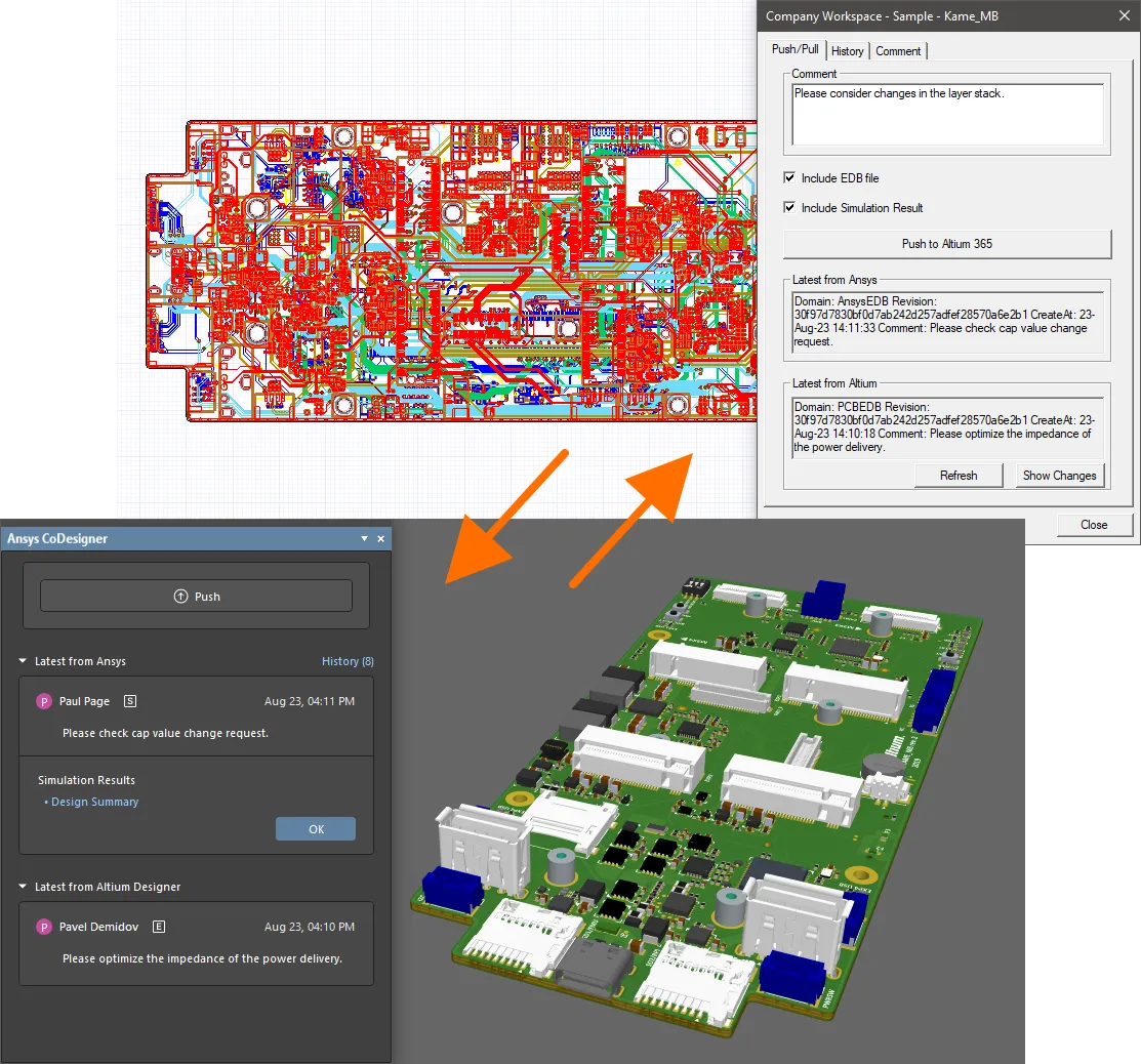
Once the Ansys CoDesigner functionality has been added to the PCB design and simulation software, it can pass design changes back and forth. Design changes are passed through an Altium 365 Workspace, which acts as a bridge between the two domains. The advantage of passing design changes through a Workspace is the update process becomes stateless. That means each side can continue to work independently; there is no need to worry about where the other team is up to in the design/simulation process.
Ansys CoDesigner facilitates the bi-directional push/pull of design changes between the two domains. From Altium Designer, changes to layer stack and materials, components and primitives are detected and can be applied in AEDT. From AEDT, proposed changes to layer stack and materials can be pushed through the EDB file and detected/applied in Altium Designer. ECAD and simulation engineers can communicate with the commenting system, with each comment thread attached to a specific component in a design. Simulation results can be pushed from AEDT to the Altium 365 Workspace and associated with a revision of the design, with the ability to view through the Workspace’s browser interface and preview within Altium Designer.
The Collaboration Interface
-
In Altium Designer, the Ansys CoDesigner panel is used to Push and Pull design changes back and forth and display messages.
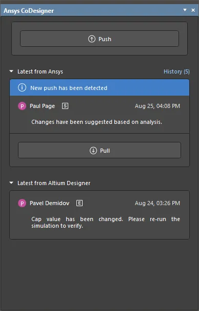
The Ansys CoDesigner panel is accessed from the PCB editor in Altium Designer by clicking the Panels button at the bottom-right of the design space and selecting the Ansys CoDesigner option from the menu that appears. Note that you must be connected to a Workspace to access the panel, and the PCB document must be a part of a PCB project stored in this Workspace so you can use the functionality.
-
In AEDT, dialogs accessed from the Layout Links dialog (Tools » Layout Links) or from the Desktop tab of the ribbon when a project is opened are used to:
- Connect to your Altium 365 Workspace and import a PCB design from it.
- Push the design to and pull it from the Workspace.
- Explore the history of data exchange between Altium Designer and AEDT.
- Add comments to components in the design.

Pushing Changes from Altium Designer
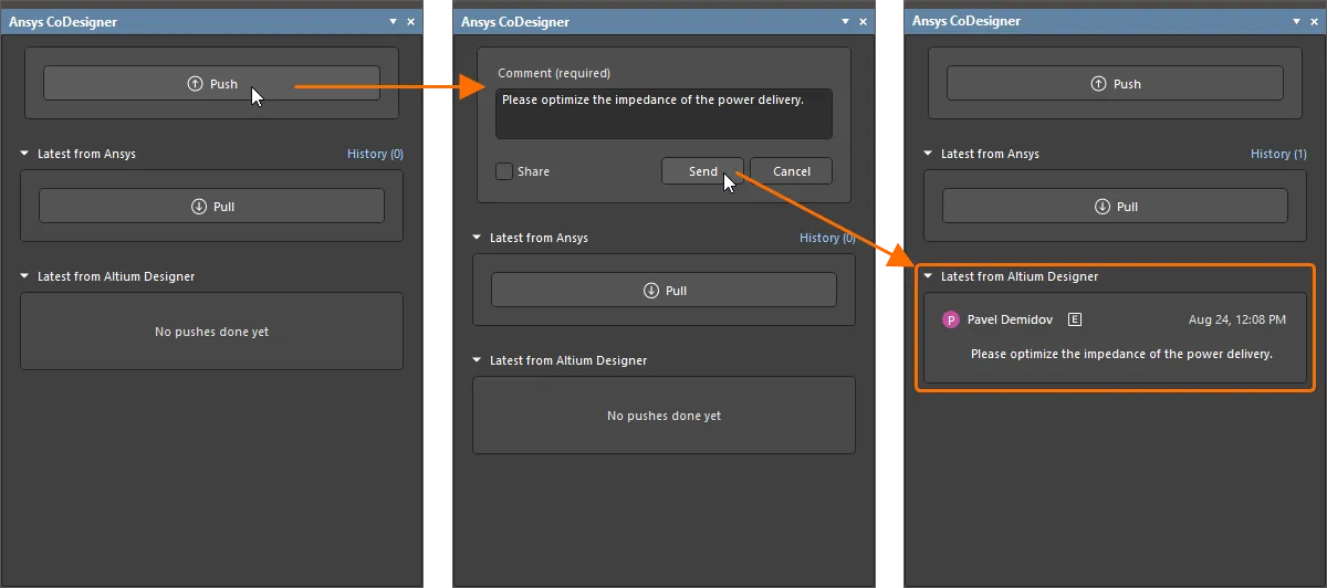
To push the design from Altium Designer, click the Push button in the Ansys CoDesigner panel. An editing window appears at the top of the panel. Enter a message about the design change, then click Send. The Latest from Altium Designer region of the Ansys CoDesigner panel will be updated with the details on this push.
The design can then be imported to AEDT. For a design that has already been imported, the changes can be pulled to AEDT.
Push and Share to Invite a Simulation Engineer
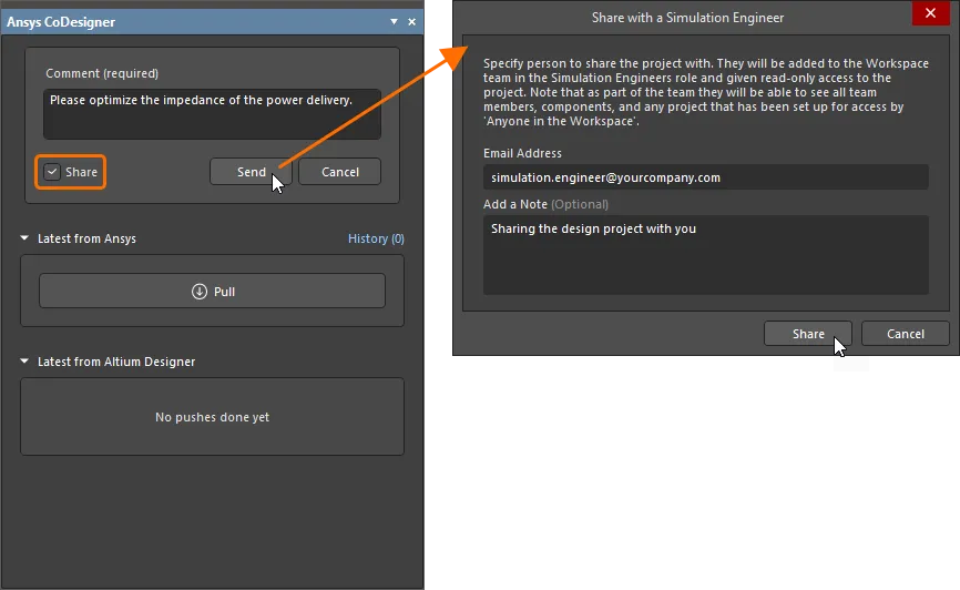
When you click Push in the Ansys CoDesigner panel, you can also enable the Share option below the Comment field to email an invitation to the simulation engineer using the Share with a Simulation Engineer dialog that opens after clicking the Send button.
Enter the email address of the simulation engineer and an optional note (if required), then click the Share button. You are able to share with a person who is already a member of your Workspace team, another registered Altium user in or outside of your organization, or a user who does not have an Altium account. A notification dialog may pop up to alert you that the user whose email you entered might be outside of your organization – click OK to invite them anyway.

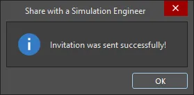
After a short delay, another dialog will appear to flag that the invitation was sent successfully.
As part of the invite process:
- A user who is already a member of your Workspace team will have the project shared with them with View rights, and they will receive an invitation email with which to gain access to the project within the Workspace.
- A user who is not a member of your Workspace team but has an Altium account (regardless of whether they are in or outside of your organization) will be added as a member of the Workspace team, and the project will be shared with them with View rights. They will receive an invitation email with which they can gain access to the project within the Workspace.
- A user with no Altium account will receive an email directing them to an intermediate form to sign up/register for an Altium account. They will be added as a member of the Workspace team upon signing up, and the project will be shared with them with View rights.
Pulling Changes to Altium Designer
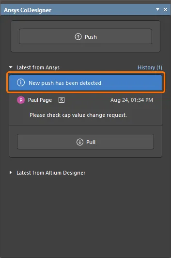
When new changes are pushed from AEDT, the New changes have been detected banner automatically appears in the Ansys CoDesigner panel. The panel will detail the name of the simulation engineer who performed the Push and the optional comment they entered when they Pushed.
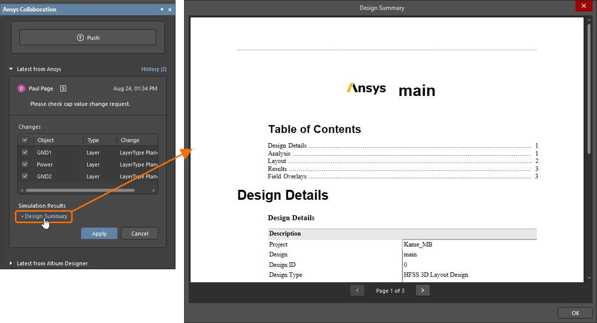
When the Pull button is clicked and if the EDB file has been included in the Push from AEDT, each change that needs to be made to the working file to synchronize it with the snapshot on your Workspace is listed. Each detected difference is listed in the Changes list in the panel. Clear the checkbox for each change you do not want to apply. When you are ready, click the Apply button to apply all enabled changes to the design.
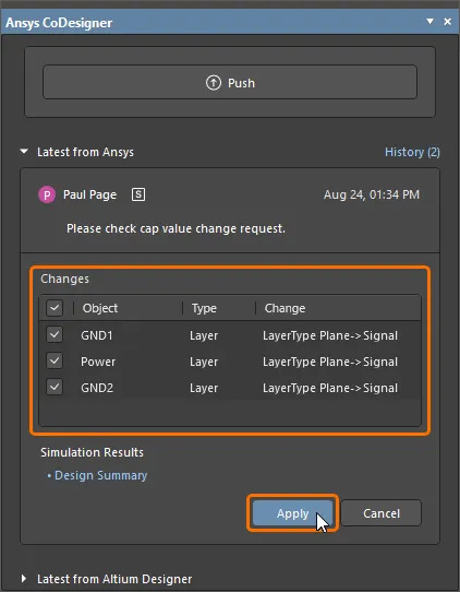
If the simulation results have been included in the Push from AEDT, the Design Summary control will be presented in the panel. Click the control to present the simulation results in the Design Summary dialog.
Importing a Design to AEDT
To start working on a PCB design in AEDT, it must be imported to AEDT first. To do this:
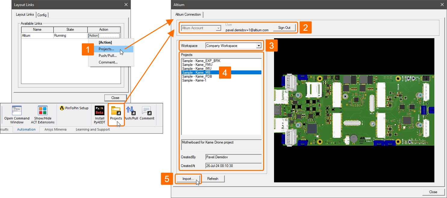
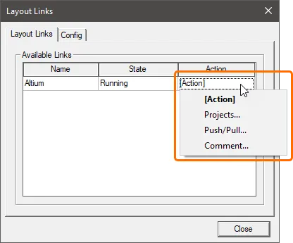
- In the Layout Links dialog (Tools » Layout Links), click the [Action] cell for the Altium link on the Layout Links tab and select Projects. Alternatively, click the Projects button on the Desktop tab of the ribbon when a project is opened. The Altium dialog will open.
-
Sign in to your Altium account. Make sure that the Altium Account entry is selected in the drop-down at the top of the dialog and click the Sign In button. A page will open in your default browser where you can enter your Altium account credentials or use SSO to sign in to your Altium account – show example.
- Select the Workspace where the required project resides from the Workspace drop-down list.
-
Select the project in the Projects list and click the Import button.
- Save the AEDT project file using the Save As dialog that opens, and then close the Altium dialog.
Pushing Changes from AEDT
To push the design from AEDT:
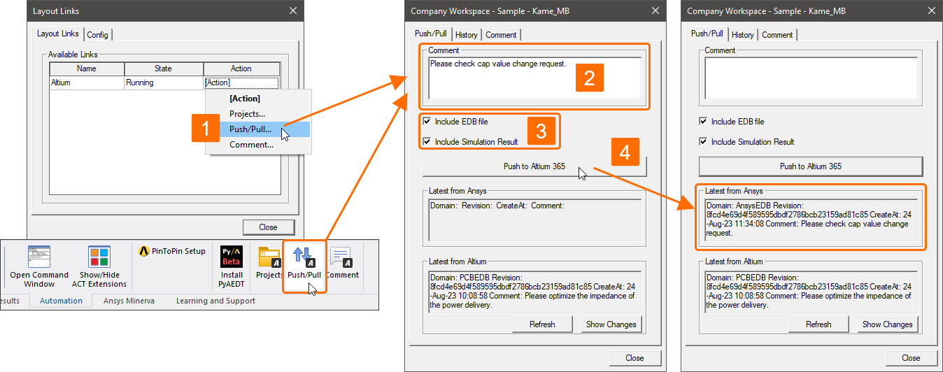
- In the Layout Links dialog (Tools » Layout Links), click the [Action] cell for the Altium link on the Layout Links tab and select Push/Pull. Alternatively, click the Push/Pull button on the Desktop tab of the ribbon when the project is opened.
- Use the Comment field at the top of the dialog that opens to add a comment that describes what is included in the Push.
- Enable the Include EDB file (to push the design changes) and/or Include the Simulation Result (to push the simulation results) options.
- Click the Push to Altium 365 button. The Latest from Ansys region of the dialog will be updated with the details on this push.
The push will be detected in Altium Designer, and it can be pulled to Altium Designer as described above.
Pulling Changes to AEDT
When design changes have been pushed from Altium Designer, they can be pulled in AEDT.
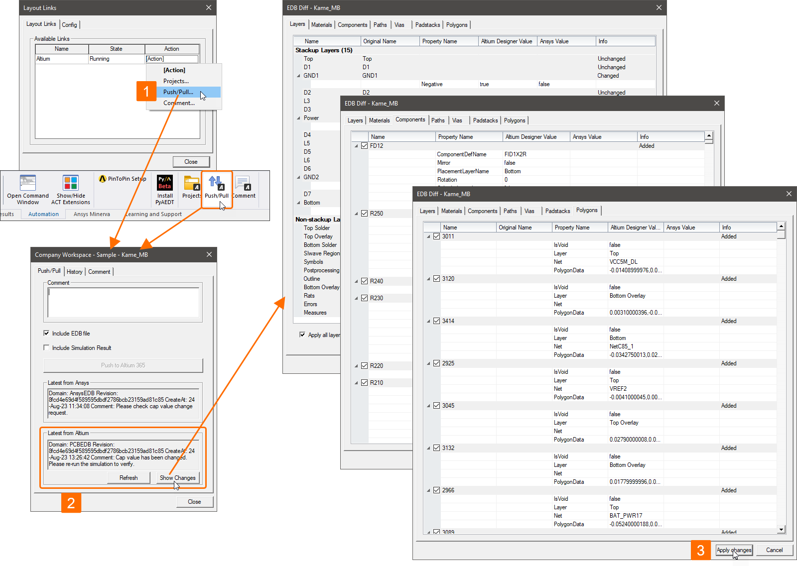
- In the Layout Links dialog (Tools » Layout Links), click the [Action] cell for the Altium link on the Layout Links tab and select Push/Pull. Alternatively, click the Push/Pull button on the Desktop tab of the ribbon when the project is opened.
-
Check the Latest From Altium region of the dialog that opens for information about the latest push from Altium Designer and click the Show Changes button to open the dialog where the differences between the design in the Workspace and the current design in AEDT are described. Use the checkboxes provided on the tabs of the dialog to select changes that you would like to apply to the design in AEDT.
- Once the changes are reviewed, click the Apply changes button to apply the changes to the design in AEDT.
Exploring the Exchange History
The history of pushes and pulls of the design is retained.
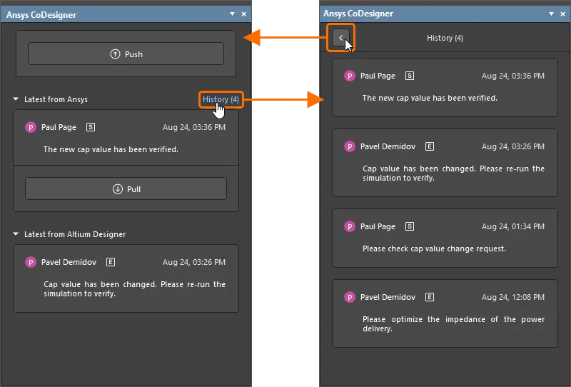
To examine the history in Altium Designer, click the History control to the right of the Latest from the Ansys region title in the Ansys Codesigner panel. The list of pushes and pulls from both Altium Designer and Ansys will open. Use the ![]() button at the top of the panel to return to the latest changes.
button at the top of the panel to return to the latest changes.
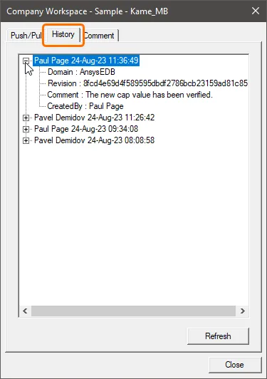
To examine the history in AEDT, click the [Action] cell for the Altium link on the Layout Links tab of the Layout Links dialog (Tools » Layout Links) and select Push/Pull or Comment or click the Push/Pull or Comment button on the Desktop tab of the ribbon. Select the History tab of the dialog that opens. Expand an entry for a push/pull to see its details. Use the Refresh button to refresh the tab with the latest data.
Adding Comments in Altium Designer and AEDT
Both electrical and simulation engineers can also benefit from the Workspace's support for comments by creating comment threads attached to specific components.
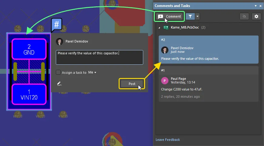
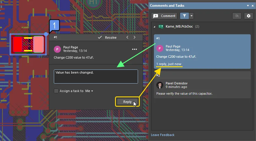
In Altium Designer, the existing comments are available through the Comments and Tasks panel.
-
To add a new comment to a component on the PCB, click the Comments button at the top of the panel, hover the cursor over a component in the design space so it is highlighted with a blue border, and click. In the comment entry dialog that opens, type the comment and click Post.
-
To reply to a comment, select the comment entry in the Comments and Tasks panel, type the reply in the provided text field in the comment entry dialog, and click Reply. The reply will be added to the comment thread.
Refer to the Document Commenting page to learn more.
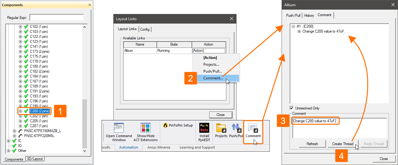
In AEDT, comment threads are managed through the Comments tab of the Altium dialog accessed by clicking the [Action] cell for the Altium link on the Layout Links tab of the Layout Links dialog (Tools » Layout Links) and selecting Comment. The list at the upper part of the dialog presents the existing comment threads for the project.
To add a comment to a component in AEDT:
- Select a specific component in the Components panel (View » Components) or in the design space.
- In the Layout Links dialog (Tools » Layout Links), click the [Action] cell for the Altium link on the Layout Links tab and select Comment.
- Type the comment in the Comment field at the lower part of the dialog that opens.
- Click the Create Thread button. A new thread will be added to the list.
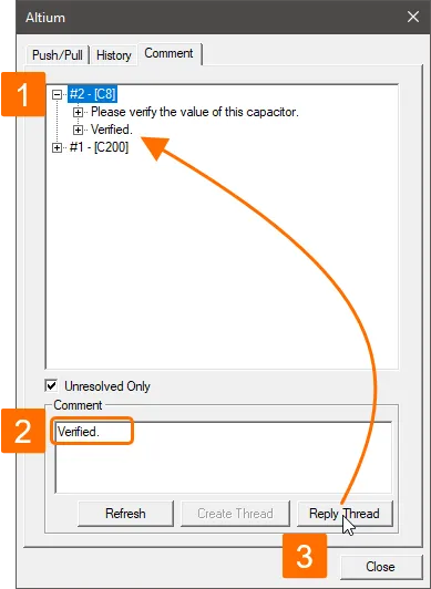
To reply to an existing thread from AEDT:
- Select a numbered comment entry in the list on the Comments tab of the Altium dialog.
- Type the reply in the Comment field at the lower part of the dialog.
- Click the Reply Thread button. A new reply will be added under the entry of the related comment thread in the list.

