Chinese - Translation is available for Altium Designer 24:
Go to the pageIt is time to position the components in suitable locations on the board and then route it.
Positioning the Components on the PCB
Main page: Component Placement
There is a saying that PCB design is 90% placement and 10% routing. While you could argue about the percentage of each, it is generally accepted that good component placement is critical for good board design. Keep in mind that you may need to also tune the placement as you route.
To move a component, Click, Hold&Drag to move the component to the required location, rotate it with the Spacebar (in increments of 90º counterclockwise), then release the mouse button to place it. The connection lines are automatically reoptimized as you move a component. Use them to help orient and position the components to reduce the number of connection line cross-overs.
Once you have placed the components, the PCB should look like the image below.

Components have been positioned on the board, ready for routing.
-
Zoom to display the board and the component.
-
The components will be positioned on the current snap grid. For a simple design such as this, there are no specific design requirements that dictate what placement grid should be used. As the designer, you decide what a suitable placement grid would be. To simplify the process of positioning the components, you can work with a large placement grid. Check the Status Bar to confirm that the Snap Grid is set to 1 mm. Use the View » Grids » Set Global Snap Grid command from the main menus if required.

-
To place connector P1:
-
Position the cursor over the middle of the outline of the connector and use Click, Hold&Drag. The cursor will change to a crosshair and jump to the center of the nearest pad of the component.
-
While continuing to hold down the mouse button, move the mouse to drag the component. Note how the connection lines drag with the component.
-
Press the Spacebar to rotate the component if required, and position the component towards the left-hand side of the board as shown in the image above.
-
When the connector component is in position, release the mouse button to drop it into place.
-
Reposition the remaining components, using the image above as a guide. Use the Spacebar to rotate components as you drag them so that the connection lines are as shown in the image.
-
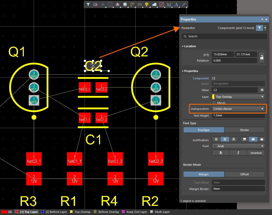
Reposition the component designators. This can be done in a similar fashion. Use Click, Hold&Drag to move the text and press the Spacebar to rotate it. Alternatively, use the Autoposition option in the Properties panel when the designator(s) are selected in the design space ( ).
).
-
Save the PCB document locally by right-clicking its entry in the Projects panel and selecting Save from the context menu.
With the components positioned, it is time to do some routing!
Interactively Routing the Board
Main page: Interactive Routing
In this part of the tutorial, you will route the board.
Routing is the process of laying tracks and vias on the board to connect the component pins. The PCB editor makes this job easy by providing sophisticated interactive routing tools. These tools help maximize routing efficiency and flexibility in an intuitive way, including cursor guidance for track placement, single-click routing of the connection, pushing obstacles, and automatically following existing connections, all in accordance with applicable design constraints.
Notes on Interactive Routing
-
Use the PCB Editor – Interactive Routing page of the Preferences dialog to configure the interactive routing options.
-
To start interactive routing, select the Route » Interactive Routing command from the main menus (shortcut: Ctrl+W), then click a net object (e.g., pad).
-
Move the cursor to see routes following the cursor. Routes on a PCB are made from a series of straight segments and/or arcs. Each time there is a change of direction, a new track/arc begins.
-
Click to place hatched track segments. Placed segments are shown as solid.
-
When you click on the destination pad to finish a route, the cursor is released from the current route. You will remain in interactive routing mode, ready to select the next connection to be routed.
-
As you place tracks on the board, use connection lines to guide you.
-
Useful shortcuts during routing:
-
Shift+F1 – pop up a menu of interactive shortcuts. Most settings can be changed on the fly by pressing the appropriate shortcut or selecting from the menu.
-
Tab – open the Properties panel, where you can change the routing settings.
-
Shift+Spacebar – cycle through the various track corner modes.
-
Spacebar – toggle the current corner direction.
-
Shift+R – cycle through routing conflict resolution modes as you interactively route.
-
3 – cycle through the routing width choices: Rule Minimum / Rule Preferred / Rule Maximum / User Choice.
-
* (on the numeric keypad) or Ctrl+Shift+Mouse Wheel – switch to the next available signal layer. A via is automatically added in accordance with the applicable via style constraint.
-
Backspace – rip up the last-placed segment for the connection that you are currently routing.
-
Ctrl+Click – auto-complete the connection being routed. Auto-complete will not succeed if there are unresolvable conflicts with obstacles.
-
Right-Click – drop the current connection and remain in interactive routing mode. Right-Click again to exit interactive routing mode.
Refer to the PCB Editor & PCB Footprint Editor Shortcuts page to learn more.
-
If it is required to modify an existing route, you can Click, Hold&Drag a placed track segment to interactively slide routing across the board.
A video that shows the board being routed. Some connections are finished using Ctrl+Click to autocomplete.
-
Before starting to route, configure the interactive routing options in the PCB Editor – Interactive Routing page of the Preferences dialog.
-
Click the  button at the top of the design space to open the Preferences dialog and then expand the PCB Editor category in the left tree and select the Interactive Routing entry in this category to open the page.
-
In the Routing Conflict Resolution region of the page, set Current Mode to Walkaround Obstacles.
-
In the Interactive Routing Width Sources region of the page, make sure that the Track Width Mode and Via Size Mode options are both set to Rule Preferred.
-
Click OK to save changes and close the dialog.
-
Set the snap grid to 0.25 mm using the Snap Grid dialog (View » Grids » Set Global Snap Grid).
-
Click on the Top Layer tab at the bottom of the design space to make it the active layer, ready to route on.

-
Select the Route » Interactive Routing command from the main menus (shortcut: Ctrl+W). The cursor will change to a crosshair, indicating you are in interactive routing mode.
-
Position the cursor over the lower pad on connector P1.
-
Click to anchor the first point of the track.
-
Move the cursor below the pad and click to place a vertical segment.
-
Route by clicking to commit track segments, finishing on the lower pad of R2.
-
Continue to route all the connections on the board. The video above shows the board being interactively routed.
-
When you finish routing, save the PCB document locally by right-clicking its entry in the Projects panel and selecting Save from the context menu.
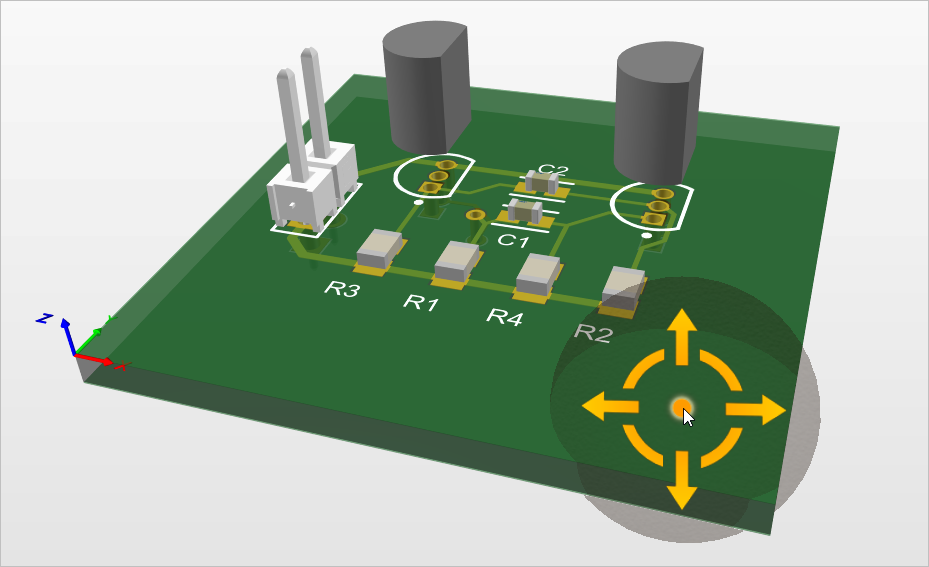
A powerful feature of Altium Designer is the ability to view your board as a 3-dimensional object. To switch to 3D, run the View » 3D Layout Mode command from the main menus (shortcut: 3). The board will be displayed as a 3-dimensional object. The tutorial board is shown below.
To navigate a board in 3D, you can use the following controls:
-
Zooming – Ctrl+Mouse Wheel
-
Panning – Right-Click, Hold&Drag.
-
Rotation – Shift+Right-Click, Hold&Drag. Rotational movement of the model is made about the center of a directional sphere that appears at the current cursor position when you press Shift.

Refer to the Controlling the 3D View page to learn more.