Altium Designer设计演示教程

您正在阅读的是 20. 版本。关于最新版本,请前往 Altium Designer设计演示教程 阅读 25 版本
 

欢迎使用Altium的世界一流电子设计软件进行电子产品开发。本教程将通过介绍从构思到输出文件的整个简单PCB设计过程,指导您学习如何使用软件。如果您不熟悉Altium软件,建议阅读“探索Altium Designer”页面,了解更多关于界面的信息、面板使用信息,以及设计文档管理概述。

如需进一步了解关于命令、对话框、对象或面板的信息,请在光标位于该对象上方时按F1键。


设计

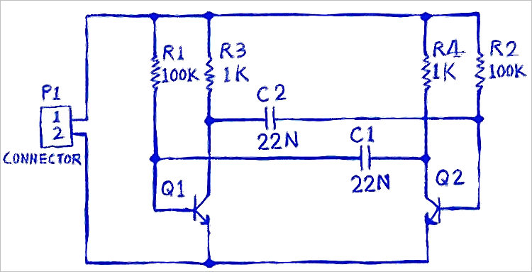
您将要为一个简单的无稳态多谐振荡器设计创建原理图并设计印刷电路板(PCB)。电路如下图所示;它使用两个配置成自运行无稳态多谐振荡器的通用NPN晶体管。

Circuit for the multivibrator 多谐振荡器电路。

您已经准备好开始输入(绘制)原理图。第一步是创建一个PCB项目。


创建一个新的PCB项目

在Altium的电子设计软件中,PCB项目是指定和制造印刷电路板所需的一组设计文档(文件)。项目文件,例如Multivibrator.PrjPCB,是一个ASCII文件,列出了项目中的文档以及其他项目级设置(例如,所需的电气规则检查)、项目优选设置,以及项目输出(例如,图纸和CAM设置)。

通过运行文件»新建»项目命令打开创建项目对话框,创建一个新项目。

Create Project dialog

与创建本地项目一样,“创建项目”对话框可用于创建版本控制项目,或存储在托管内容服务器中的托管项目。使用链接了解有关该等类型项目的更多信息。

A new project is created by running the File » New » Project command to open the Create Project dialog.

Create Project dialog

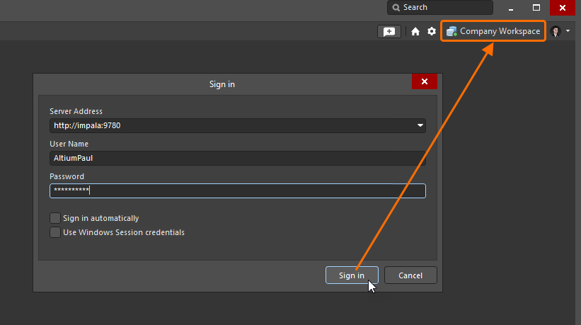
Altium NEXUS is built for collaborative design, with features that help keep the design team members in sync. A key ingredient to delivering these collaboration capabilities is the way that designs are managed - by storing them in a Managed Content Server. To complete this tutorial, you will need to be signed in to a Managed Content Server.

Connect to Server

Learn more about Collaborative Design
Learn more about Working with a Managed Content Server


向项目添加原理图

下一步是向项目添加新的原理图。

Add a new schematic to the project

将原理图添加到项目中,命名并保存原理图,然后保存项目。

打开空白原理图时,您会注意到工作区发生变化。菜单栏包含新的条目,并且一个带按钮的工具栏变得可见——您现在位于“原理图编辑器”中。每个编辑器都有自己的一组菜单和面板,并且支持自己的快捷键集。

可以使用面板右上方的图标 Close panels button 关闭整组浮动面板,也可以通过右键单击单个面板的名称,单独关闭该面板。需要时,可以通过应用程序右下方的按钮  Panels button 重新打开面板。或者,按F4快捷键隐藏/显示所有浮动面板。


设置文档选项

面板页面:原理图文档选项

在开始绘制电路之前,最好设置适当的文档选项,包括“图纸尺寸”、“捕捉”和“可见”栅格。

Properties panel, document options 为每个原理图配置文档选项,并根据要求设置图纸尺寸。

除下文可折叠部分中描述的操作外,还可以通过双击图纸边框来访问“文档选项”属性。

优选设置对话框工具»优选设置)中配置环境选项,例如光标类型、选择后显示的颜色和自动平移性能。


访问元件

相关文章:关于元件和库的更多信息

安装在电路板上的实际元件在设计输入期间用原理图符号表示,在电路板设计中用PCB封装表示。

元件可以:

  • 直接从制造商部件搜索面板放置。通过该面板,您可以即时访问功能强大的最新元件搜索和集合系统,该系统详细列出了来自数千家制造商的数百万个元件,以及每个元件的实时供应链信息。其中许多元件随时可以设计,并且带有符号和封装模型。这些零部件将在面板中显示相应图标  Has Models icon 
  • 本地文件库或贵公司托管内容服务器中创建并从中放置元件。这些元件通过“元件”面板搜索和放置。关于该方法的更多信息,请参见下文使用您自己的元件部分。
  • Created in and placed from your company's Managed Content Server, these components are searched for and placed through the Components panel. 
    Learn more about managed components
  • 就本教程而言,所有元器件均来自“制造商部件搜索”面板。
  • 在整个教程中,术语“元件”和“部件”均用于描述将要放置和连线的设计元件。

搜索新部件

主要文章:制造商部件搜索面板

首选在“制造商部件搜索”面板中查找新的元件。如需打开“制造商部件搜索”面板,请单击应用程序右下方的按钮 Panels button ,然后从菜单中选择“制造商部件搜索”(显示图片)。当前可见的面板在菜单中被勾选标记。

第一次打开“制造商部件搜索”面板时,面板将显示一个元件“类别”列表,如下所示。

Manufacturer Parts Search panel 执行搜索之前的“制造商部件搜索”面板。

利用Altium Designer的高级元件搜索引擎,可以通过在主“搜索”字段中输入查询,在直接搜索模式下使用“制造商部件搜索”面板,或者通过使用“类别”和“过滤器”选项逐步完善搜索条件,从而在其高级分面模式下使用“制造商部件搜索”面板——或者通过两种功能的结合,使用“制造商部件搜索”面板。

  • 如需执行直接搜索,请在面板顶部的“搜索”字段中输入搜索描述。

例如:LED绿色透明0603 SMD

Manufacturer Parts Search panel, simple search 使用“搜索”字段执行基于文本的搜索。单击搜索字符串旁边的小x清除它,然后单击搜索字符串,将其重新加载到“搜索”字段中以进行编辑。

  • 或者,如需执行分面搜索,请使用“类别”和“过滤器”,通过在条件开启和关闭之间切换,搜索所需零部件。

例如:

  1. 首先选择一个“类别”,如LED,
  2. 然后按“颜色”、“外壳/封装”、“安装”、“有模型”等过滤LED类别。

Manufacturer Parts Search panel, faceted search 或者,结合使用“类别”、“过滤器”和“搜索”字段执行分面搜索。

支持搜索元件的面板和对话框具有横向模式和纵向模式。调整面板/对话框的大小时,控件将重新排列,因此它们可能与本文显示和描述的排列方式不完全相同。

探索搜索结果

面板的搜索结果区域显示完全或部分符合搜索条件的制造商部件列表。单击一个部件后,该部件将被选中,并且将显示一个链接,通过该链接可以访问关于该部件的最新供应链信息。

Manufacturer Parts Search panel, details of the selected part

理解供应商图块

每个SPN图块中都包含大量信息。将光标悬停在图标或详细信息上以显示更多信息。

Manufacturer Parts Search panel, Supplier Part Number tile SPN图块包含关于部件及其可用性的详细信息。


使用您自己的元件

在某些时候,您将需要创建自己的元件并将其存储在本地。主要有两类元件可供创建:

  • 托管元件 - 在“托管内容服务器”中创建和存储的元件。
    了解更多关于托管元件的信息
  • 非托管元件 - 元件被创建并存储在Altium格式的库文件中。这些被称为基于文件的库或文件库。
    了解更多关于基于文件的元件和库的信息

托管和非托管元件都将在元件面板中浏览、搜索和放置。与制造商部件搜索面板一样,元件面板支持基于字符串的搜索、分面搜索或两者相结合。使用  Panels button 按钮显示元件面板。

Components panel 元件”面板用于浏览存储于托管内容服务器中的元件;悬停以显示的面板用于浏览基于文件的元件。

在本教程中,所有元件都将从“制造商部件搜索”面板放置。本节信息主要帮助您大致了解如何使用非托管元件。


从“制造商部件搜索”面板放置到原理图上

如果您在制造商部件搜索面板中找到的元件有Altium设计模型,则将显示相应的图标  Has Model icon 如果元件有模型,则原理图符号和封装模型将列在面板的“详细信息”区域中(单击面板中的  Manufacturer Part Search panel, part information 按钮以显示该区域)。该元件可以直接从面板放置到当前原理图上。

Manufacturer Part Search panel, faceted search results 使用“制造商部件搜索”面板中的分面搜索功能以只显示有模型的元件。

面板的“过滤器”区域包含一个“有模型”过滤器。启用此选项仅显示准备就绪的元件。单击 Manufacturer Part Search panel, Filters button 以显示可用过滤器。

如需从面板放置元件,您可以:

  • 从下载按钮选择放置——光标自动移动范围应在原理图边界内,并且元件显示浮在光标上;对其进行定位然后单击放置。放置元件后,相同元件的另一个实例将出现在光标上;右键单击以退出放置模式。
  • 右键单击元件,然后从上下文菜单中选择“放置”。元件显示附着在光标上;对其进行定位然后单击放置。请注意,如果面板悬在工作区上方,则其将渐隐,以便允许您查看原理图并放置元件。放置元件后,相同元件的另一个实例将出现在光标上;右键单击以退出放置模式。
  • 单击并拖动——单击并将元件从面板区域拖到该图纸上。此模式需要按住光标;当放开光标时放置元件。使用此技巧,只能放置一个元件。放置元件后,您可以自由选择另一个元件或另一个命令。

放置提示

当元件附着在光标上时,您可以:

  • 空格键将其逆时针旋转,旋转角度以90度递增。
  • X键使其沿X轴翻转;按Y键使其沿Y轴翻转。
  • Tab键显示“属性”面板,并在放置对象之前编辑对象的属性。输入的值变成默认值。如果位号标识符有相同的前缀,则其将自动递增。
  • 在元件放置过程中,如果您碰到窗口边缘,则软件将自动移边。在优选设置对话框原理图 - 图形编辑页面中配置自动移边。如果当元件附着在光标上时,您的平移量不小心超出所需范围,则您可以:
    • 使用Ctrl +滚轮再次缩小或放大,或
    • 通过右键单击并拖动以在原理图上四处滑动,或
    • 使用Ctrl + PgDn再次显示整个图纸。
  • 如果放置元件时,制造商部件搜索面板悬浮在原理图上,则每当光标+元件靠近它时,它都会自动变为透明。浮动面板的透明度可以在“优选设置”对话框的“系统 - 透明度”页面中进行配置。或者,也可以通过按F4快捷键,随时隐藏/显示所有浮动面板(无论是否在运行命令)。

了解更多关于原理图放置和编辑技巧的信息

在“放置”过程中使用“属性”面板

在对象放置过程中,如果按Tab键,则编辑过程将暂停,并且交互式属性面板将打开。默认行为是突出显示最常用的编辑字段以供编辑。由于编辑过程暂停,您可以使用光标(或按键盘上的Tab键)移动至面板中的另一个区域。

完成编辑后,单击“暂停”按钮 ( Pause button ) ,如下图所示,以返回对象放置。或者,按Enter键完成对象编辑并返回对象放置。

Demonstration of pausing to edit the schematic component properties on the fly

当您在放置过程中按下Tab键时,编辑被暂停——单击屏幕上的“暂停”图标以返回放置元件。


放置多谐振荡器元件

现在,可以使用制造商部件搜索面板来查找下表中列出的多谐振荡器电路所需的元件了。

DESIGNATOR 位号标识符 Comments
Q1, Q2 General purpose NPN transistor, eg BC547 or 2N3904 Search for: transistor BC547, chose BC547CG
R1, R2 100K resistor, 5%, 0805 Search for: resistor 100K 5% 0805
R3, R4 1K resistor, 5%, 0805 Search for: resistor 1K 5% 0805
C1, C2 22nF capacitor, 10%, 16V, 0805 Search for: capacitor 22nF 16V 0603
P1 2-pin header, thruhole Use the faceted search feature to filter for a: Connector, 2-pin, vertical, male, header

元件放置完毕后,原理图应如下图所示。

您可以继续查找和放置元件。请注意,下文可折叠部分包含了在放置过程中进行编辑的提示。在放置过程中进行编辑比在放置后进行编辑更有效率。如果您选择将编辑留到元件放置完毕后进行,则可单击以选择元件并在“属性”面板中对其进行编辑。

Multivibrator schematic, parts placed 所有元件均已放置完毕,随时可以连线。

在属性面板中编辑

“属性”面板的其中一项强大功能是支持同时编辑多个选定对象。

  • 如果所有对象共享一个属性,则该属性可用于编辑。
  • 如果所有对象共享相同的属性值,则将显示该值。
  • 如果对象共享相同的属性但属性值不同,则将显示星号(*)。
  • 输入的值或选择的选项将被应用于所有选定对象。

Demonstration video, editing in the Properties panel 使用“属性”面板编辑多个选定对象的属性。旋转选定元件以移动其字符串至默认位置。

现在,您已经放置了所有元件。请注意,上图中显示的元件是隔开放置的,以便有足够的空间连线至每个元件管脚。这一点很重要,因为您没办法在原理图符号下面连线到另外的管脚,否则两个管脚都将与导线相连。如果您需要移动一个元件,单击并按住元件,然后拖动鼠标以重新定位元件即可。

元件定位提示

  • 如需重新定位任何对象,请将光标直接放在该对象上,单击并按住鼠标左键,将对象拖到新位置,然后放开鼠标按钮。移动遵照“状态栏”上显示的当前捕捉栅格而进行。随时按G快捷键可在当前捕捉栅格设置之间循环。请记住,将元件放置在粗体显示的整数栅格(例如,50或100密尔)上。
  • 将元件放置在原理图上后,如果元件被移动,则软件将尝试保持连接(保持导线连接)。这种连接感知移动被称为拖动。如需在不保持连接的情况下移动元件,请在按住Ctrl的同时单击并拖动元件。如需将默认行为从拖动切换为移动,请禁用“优选设置”对话框“原理图 - 图形编辑”页面中的“始终拖动”选项。
  • 由于原理图编辑器默认始终拖动,因此不能使用“空格键”旋转放置的元件。如需旋转放置的元件,请按“Ctrl +空格键”。
  • 您也可以使用键盘上的箭头键重新定位一组选定原理图对象。选择对象,然后在按住Ctrl键的同时按下箭头键。同时按住Shift键可将对象移动相当于当前捕捉栅格10倍的量。
  • 在用鼠标移动对象时,也可以将栅格临时设置为1;按住Ctrl即可执行此操作。定位文本时使用此项功能。
  • 当您按下G键时循环的栅格将在优选设置对话框(工具»优选设置)的原理图-栅格页面中定义。优选设置对话框原理图-常规页面上的“单位”控件用于选择测量单位;选择密尔毫米。请注意,Altium元件是使用英制栅格设计的;如果您改为公制栅格,则元件管脚将不再落在标准栅格内。因此,除非您计划只使用自己的元件,否则建议使用密尔作为单位

电路连线

连线是在电路的各个元件之间建立连接的过程。要连接原理图,请参考电路草图和下文所示动画。

Demonstration video, wiring the multivibrator schematic

使用“连线”工具对电路进行连线。在动画快结束时,您可以看到如何拖动导线。

活动工具栏

可以通过“活动工具栏”,使用每个编辑器中最常用的工具,“活动工具栏”显示在编辑窗口的顶部。

Place a Net Label, using the Active Bar

活动工具栏”上的按钮要么是单功能按钮,要么是多功能按钮。多功能按钮由一个小三角形表示。单击按钮上的任意位置并按住一秒钟。屏幕上将出现一个菜单,列出其他可用命令。最后使用的命令将成为该按钮位置的默认命令。

连线提示

  • 使用Ctrl + W快捷键启动放置»导线命令。
  • 左键单击或按Enter键将导线固定在光标位置。
  • Backspace键删除最后一个定位点。
  • “空格键”可切换转角方向。在上文所示动画快结束时,您可以在连接器画线时看到这项操作。
  • Shift +空格键可在连线转角模式之间循环。可用模式包括:“90度角”、“45度角”、“任意角度”和“自动连线”(在单击点之间放置正交线段)。
  • 右键单击或按Esc键退出导线放置模式。
  • 单击并按住以将元件和任何相连导线一起拖动;按住Ctrl键+单击并按住以移动放置的元件。
  • 每当一条导线穿过元件连接点或终止于另一条导线时,就会自动创建一个接合。
  • 即使您删除了接合,穿过管脚末端的导线也将与该管脚相连。在继续之前,请确认您画的电路是否如图所示。
  • 如果愿意,交叉连线可以用小拱形显示。该选项可以在优选设置对话框的“原理图 - 常规”页面中启用。

网络和网络标签

现在,每组彼此连接的元件管脚各自形成了所谓的网络。例如,一个网络包括Q1的底部、R1的一个管脚和C1的一个管脚。每个网络将自动获得一个系统生成的、基于该网络中其中一个元件管脚的名称。

为了易于识别设计中的重要网络,可以添加网络标签以分配名称。对于多谐振荡器电路,您将如下所示,在电路中标记12V和GND网络。

Multivibrator schematic, complete 已向12V和GND网络添加了“网络标签”,从而完成原理图。

网络标签、端口和电源端口

  • 除了为网络命名外,网络标签还用于在相同原理图上的两个离散点之间建立连接。
  • 端口用于在不同图纸上的两个离散点之间建立连接。跨页连接器也可以用于执行此项操作。
  • 电源端口用于在所有图纸上的点之间建立连接;对于这种单页设计,则可以使用“网络标签”或“电源端口”。

恭喜您!您刚刚完成了您的第一次原理图输入。将原理图转换为电路板之前,您需要配置项目选项并检查设计是否存在错误。


设置项目选项

项目特定设置在下文所示“项目选项”对话框中进行配置(项目»项目选项)。项目选项包括错误检查参数、连接矩阵、“类生成器”,“比较器”设置、ECO生成、输出路径和连接选项、“多通道命名格式”、“默认打印”设置、“搜索路径”和项目级“参数”。

装配、制造输出和报告等项目输出可以从文件报告菜单中设置。这些设置也可以存储在项目文件中,以便始终可供该项目使用。或者,也可以使用OutputJob文件配置输出,这样做的优势是OutputJob可以从一个项目复制到另一个项目中去。参见有关输出的详细信息,了解更多关于输出配置的信息。

动态编译

“统一数据模型”(UDM)从打开项目起即可使用,并且不要求进行额外编译,因此可以提高编译速度,并在“导航器”面板中持久显示网络和元件列表,从而节省时间。每次用户操作后,设计连接模型都会进行增量更新。这意味着不再需要进行项目编译即可查看“导航器”面板的内容,运行“材料清单”(BOM)或执行“电气规则检查”(ECO)。下列各项将不再需要手动编译:

  • 导航器项目面板
  • ActiveBOM
  • 交叉探测
  • 网络颜色突出显示
  • 管脚交换
  • 元件交叉引用

检查原理图的电气特性

原理图不仅仅是简单的图——它们还包含了与电路有关的电气连接信息。您可以使用这种连接关系来核实您的设计。编译项目时(项目»验证PCB项目),软件将检查UDM和编译器设置之间的逻辑、电气和绘图错误。检测到的所有违规都将显示在消息面板中。

设置错误报告

对话框页面:错误报告

项目选项对话框中的错误报告选项卡用于设置各种绘图和元件配置检查。报告模式设置显示违规的严重性级别。如果您想要更改设置,请单击要更改的违规旁边的“报告模式”,然后从下拉列表中选择严重性级别。

Options for PCB Project dialog, Error Reporting tab 配置错误报告选项卡以在编译项目时检测设计错误。

设置连接矩阵

对话框页面连接矩阵

随着设计的推进,每个网络中的管脚列表都被集成到内存中。首先检测每个管脚的类型(例如,输入、输出、无源等),然后检查每个网络以查看是否存在不应该相互连接的管脚类型,例如,输出管脚与另一个输出管脚相连。在项目选项对话框的连接矩阵选项卡中,可以配置允许哪些管脚类型相互连接。例如,查看矩阵图右侧条目,然后找到“输出管脚”。交叉参照矩阵的这一行,直到获得“集电极开路管脚”列为止。它们相交的方块用橙色表示,说明在编译项目时,连接到原理图上的“集电极开路管脚”的“输出管脚”将生成错误情况。

您可以为每个错误类型设置单独的错误级别,即从无报告致命错误。单击彩色方块以更改设置;继续单击移至下一个检查级。设置矩阵,以便通过未连接 - 无源管脚生成错误,具体如下图所示。

Options for PCB Project dialog, Connection Matrix tab连接矩阵选项卡定义了在原理图上检查哪些电气条件;请注意,“未连接 - 无源管脚”设置发生了改变。

配置类的生成

对话框页面类生成

项目选项对话框中的类生成选项卡用于配置从设计生成哪种类型的类(然后使用比较器ECO生成选项卡来控制是否将类传输到PCB)。默认情况下,软件将为设计中的每个原理图生成“元件”类和ROOM,并为每个总线生成“网络类”。对于诸如此类的简单、单页设计,不需要生成元件类或ROOM。确保清除元件类复选框;此举还会禁用为该元件类创建ROOM的操作。

请注意,对话框的此选项卡还包括用户定义的类的选项。

Options for PCB Project dialog, Class Generation tab类生成选项卡用于配置自动为设计创建哪些类和ROOM。

设置比较器

对话框页面:比较器

项目选项对话框中的比较器选项卡可以设置在编译项目时将报告或忽略哪些文件间差异。通常,只有在向PCB添加额外的详细信息(例如,设计规则)并且不希望在设计同步期间删除这些设置时,才需要更改此选项卡中的设置。如果需要进行更细致的控制,则可以使用单个比较设置有选择地控制比较器。

对于本教程,只需确认忽略仅在PCB中定义的规则选项如下图所示被启用即可。

Options for PCB Project dialog, Comparator tab比较器选项卡用于精确配置比较引擎将检查的差异。

您现在可以验证项目并检查是否存在任何错误。


编译项目以检查错误

主要文章:编译和验证设计

项目编译将会检查设计文档中的绘图和电气规则错误,并在消息面板中详细说明所有警告和错误。您已经在项目选项对话框的错误检查连接矩阵选项卡中设置了规则,因此现在可以检查设计了。

如需编译项目并检查错误,请从主菜单中选择项目»验证PCB项目Multivibrator.PrjPcb

Schematic error checking, demonstrating how to inspect the error condition 使用“消息”面板定位和解决设计警告和错误;双击警告/错误以与该对象交互定位。

当您在消息面板中双击一个错误时:

  • 原理图缩放以显示出错的对象。缩放精度优选设置对话框系统 - 导航页面的“突出显示方法”部分中上面的滑块设置。
  • 除了出错的对象以外,整个原理图渐隐。原理图渐隐量由调光级控制,“调光”级则由优选设置对话框系统 - 导航页面的突出显示方法部分中下面的滑块设置。单击原理图上的任意位置以清除调光显示。

Preferences dialog, setting the zoom level when you double-click on an error in the Messages panel

  • 如需从消息面板中清除所有消息,请在面板中单击鼠标右键,然后选择全部清除
原理图输入现已完成。现在可以创建PCB了!

创建一个新的PCB

在将设计从“原理图编辑器”传输到“PCB编辑器”之前,您需要先创建一个空白PCB,然后命名并将其保存为项目的一部分。

Altium Designer, showing a new PCB added to the project
空白PCB已添加到项目中并保存,并且项目已保存。

Altium NEXUS, showing a new PCB added to the projectThe blank PCB has been added to the project and saved, the project has been saved, and the project has been committed to Version Control.


配置板形外框和电路板位置

主要文章电路板

从原理图编辑器转移设计之前,需要更改此空白电路板的多项属性,包括:

任务 Process
设置原点 The PCB editor has two origins: the Absolute Origin, which is the lower left of the workspace, and the user-definable Relative Origin, which is used to determine the current workspace location - the coordinates shown on the Status bar are relative to this origin. A common approach is to set the Relative Origin to the lower-left corner of the board shape. Select the Edit » Origin » Set command to set the Relative Origin; use the Reset command to reset it back to the Absolute Origin.
将单位设置为“英制”或“公制” The current workspace X / Y location and Grid are displayed on the Status bar, which is displayed along the bottom of the editor. For this tutorial, metric units will be used. To change the units, either press Q on the keyboard to toggle back and forth between Imperial and Metric units, or select the View » Toggle Units command from the menus.
选择合适的捕捉栅格 You may have noticed that the current snap grid is 0.127mm, which is the default 5mil imperial snap grid converted to metric. To change the snap grid at any time, press G to display the Snap Grid menu, from where you can select an imperial or metric value. Note the shortcuts shown in the menu; use Ctrl+Shift+G to open the Snap Grid dialog, which is handy when you want to type in a specific value. The other useful shortcut is Ctrl+G, which opens the Cartesian Grid editor, in which you can change the grid from dots to lines, and change the grid color. Grids are discussed in more detail later in the tutorial.
重新定义板形外框 The board shape is shown by the black region with a grid in it. The default size for a new board is 6x4 inches; the tutorial board is 30mm x 30mm. Details for the process of defining a new shape for the board are available below.
配置图层 As well as the copper, or electrical layers on which you route, there are also general-purpose mechanical layers and special-purpose layers, such as the component overlays (silkscreens), solder mask, paste mask, and so on. The electrical and other layers will be configured shortly.
  • 随时按Ctrl+PageDown键缩放以显示整个电路板。
  • 可使用下列方法放大/缩小:
    • PageUp / PageDown
    • Ctrl +滚轮
    • Ctrl +右键单击并按住+拖动鼠标

PCB editor, the board size has been defined, and the units, origin and grid have been set 电路板尺寸已定义,单位、原点和栅格也已设置。所需的图层将很快得到配置。

定义非矩形板形外框的一种好方法是在禁止布线层上放置一系列线路(以及弯曲电路板的圆弧)。这些线路和圆弧不仅可以用作禁止放置和布线障碍,而且还可以被选定(编辑»选择»层上所有对象)并用于创建板形外框(使用设计»板形外框»从选定对象中定义命令)。

►了解更多关于定义板形外框的信息

配置“默认值”

将对象放置在PCB编辑器工作区中时,该软件将根据以下内容定义对象的形状和属性:

  1. 适用的设计规则——如果定义了适用于该对象的规则,则将从该规则中定义属性对象。例如,在交互式布线时对图层进行更改期间,会自动添加一个过孔,其尺寸和孔径属性取自适用的“布线过孔样式”设计规则。
  2. 默认设置——如果适用的设计规则不存在或不适用,则对象的属性将根据优选设置对话框的PCB编辑器 - 默认页面中配置的默认设置定义。例如,如果运行放置»过孔命令,由于该软件将不知道该过孔是否将成为网络的一部分,因此它将以默认中定义的尺寸显示过孔。

Preferences dialog, configuring the default Designator font


转移设计

主要文章:在原理图和电路板之间工作

设计直接在原理图编辑器和PCB编辑器之间传输;不会创建中间网表文件。从原理图编辑器中,选择设计»更新PCB文档Multivibrator.PcbDoc,或从PCB编辑器中,选择设计»从Multivibrator.PrjPcb导入变化

运行其中任意一个命令时,您都会创建一组工程变化列表,其中:

  • 列出设计中使用的所有元件以及每个元件所需的封装。执行ECO时,软件将尝试定位每个封装,并将其放入PCB工作区。如果没有可用的封装,则会发生错误。软件可以在哪里寻找每个封装取决于:元件的创建方式(托管或非托管);对于非托管元件来说,PCB封装库当前是否可用。所有元件均已从制造商部件搜索面板放置,因此软件可以反向参考并检索每个封装。
  • 创建所有网络(连接的元件管脚)列表。执行ECO时,软件会将每个网络添加到PCB,然后尝试添加属于每个网络的管脚。如果无法添加管脚,则会发生错误;找不到封装或封装上的焊盘未映射到符号上的管脚时,最容易发生这种错误。
  • 然后,传递附加设计数据,例如网络和元件类。

PCB editor, the components have been placed outside the board shape and the nets created 一旦执行了ECO,元件将被放置在板形外框以外,并创建网络。请注意,默认位号标识符(和注释)字体已发生变化。

在将原理图信息传输到新的空白PCB之前,与原理图符号和PCB封装有关的所有库必须可用,这一点至关重要。鉴于已从制造商部件搜索面板(从托管内容服务器中获取符号和封装)放置所有元件,所以本教程所需的封装均已可用。


配置图层显示

一旦执行所有ECO,元件和网络将出现在电路板轮廓右侧的PCB工作区中,具体如上图所示。开始在电路板上布局元件之前,您首先需要配置某些PCB工作区和电路板设置,例如图层、栅格以及设计规则。

您所看到的电路板属于俯视图——即沿着Z轴俯视电路板。PCB编辑器是一个分层设计环境;构造电路板时,您放在信号层上的对象将变成铜,您放在“丝印”层上的字符串将丝印至电路板表面,而您放在机械层上的说明则将变成您所打印的装配图上的说明。

设计电路板时,您将俯视所有叠层,将元件放置在电路板顶部和底部(“顶层/底层”),并将其他设计对象放置在铜层、丝印层、掩膜层和机械层上。

Finished PCB, showing layers used 设计电路板时,您将俯视所有叠层,将光标悬停在图像上,以3D方式显示在Z轴上伸展的相同电路板位置。

“PCB编辑器”除了支持用于构造电路板的层(包括信号层、电源层、掩膜层和和丝印层)之外,还支持许多其他非电气层。层通常按以下方式分组:

  • 电气层——包括32个信号层和16个内部电源层。
  • 元件层——元件设计中使用的层,包括丝印层、阻焊层和锡膏层。如果在库编辑器中,某个对象被放置在其中一层上的元件封装内,当元件从电路板顶层翻转到底层时,“元件层”上检测到的所有对象将翻转到其对应“元件层”上。这包括用户定义的“元件层对”(成对的机械层)上的对象。
  • 机械层——软件支持用于尺寸、构造详细信息、装配说明等设计任务的无限通用机械层。如果需要,可以在打印和Gerber输出生成中有选择地纳入这些层。机械层也可以配对;当配对时,它们起到“元件层”的作用。“成对元件层”用于完成3D体放置、点胶点以及在边缘连接器上进行选择性镀金等任务。
  • 其他层——这些层包括“禁止布线层”(用于定义适用于所有铜层的禁止布线)、“多层”(用于所有信号层上存在的对象,例如焊盘和过孔)、“钻孔图层”(用于放置钻孔信息,例如钻孔表)和“钻孔引导层”(用于显示指示钻孔位置和尺寸的标记)。

铜层在“层堆栈”中向设计中添加和从设计中删除,我们将在下文中对此进行讨论。所有其他层均在视图配置面板中启用和配置。

显示层——视图配置

面板页面视图配置

视图配置面板中配置所有层的显示属性。如需打开面板:

  • 单击应用程序右下角的按钮  Panels button 然后从菜单中选择“视图配置”,或者
  • 选择查看»面板»查看配置菜单入口,或
  • L快捷键,或
  • 单击工作区左下方的当前层颜色图标 PCB editor workspace, Layer Set control

View Configuration panel, Layers & Colors tab   View Configuration panel, View Options tab “视图配置”面板的两个选项卡

除了层显示状态和颜色设置外,通过“视图配置”面板还可以访问其他显示设置,包括:

  • 系统颜色的颜色和可见性,例如“选择”颜色,或者“连接线”是否可见。
  • 每种对象的显示方式(实心或草图)及其透明度(“对象可见性”部分)。
  • 各种视图选项,例如是否显示原点标记焊盘网络名称焊盘编号其他选项部分)。
  • 当对象“调光”或“屏蔽”时,显示渐隐量(屏蔽和调光设置部分)。
  • 层集的创建,一种使用  PCB editor workspace, Layer Set control 控件(部分)快速切换当前可见层的方法。
  • “视图配置”的创建和选择,“视图配置”用于预配置所有层属性,例如颜色、可见性、对象透明度等等(常规设置部分)。

层设置提示

  • 当前启用层以PCB工作区底部的一系列选项卡的形式显示。右键单击选项卡可以访问常用层显示命令。
  • 在任务繁重的设计中,此项功能有助于只显示当前用到的层;这被称为单层模式。如需在进入/退出单层模式之间进行切换,请按Shift+S快捷键。可用单层模式优选设置对话框的PCB编辑器 - Board Insight Display页面中配置。每按下Shift + S一次,您都将循环到下一个启用的单层模式。
  • 如需切换活动层:
    • 单击工作区底部的图层选项卡,或
    • 按+或-数字键在所有图层之间循环,或
    • 按*数字键在信号层之间循环,或
    • 使用Ctrl+Shift+滚轮快捷键。
Click here to expand or collapse this section
  1. Open the View Configuration panel.
  2. In the Layers and Colors tab, confirm that the Top Layer and Bottom Layer signal layers are visible.
  3. Note that this panel is where you control the display of the mask and silkscreen layers, as well as the system layers, such as DRC and grids.
  4. To have less visual "clutter" during placement and routing, disable the display of the Mechanical Layers, Solder and Paste Mask Layers, and the Drill Guide and Drill Drawing layers.
  5. Switch to the View Options tab.
  6. Confirm that the Pad Nets and Pad Numbers options are enabled.

物理层和层堆栈管理器

主页面定义层堆栈

PCB层堆栈是成功印刷电路板设计的一个关键要素。许多现代PCB布线已经不再只是一系列简单的传递电能的铜连接,而是被设计成一系列电路元件或传输线。

设计现代高速PCB时,还有许多其他设计考量,包括:层配对、精心的过孔设计、可能的背钻要求、刚性/挠性要求、铜平衡,层堆栈对称性和材料合规性。

这些层堆栈要求在层堆栈管理器(选择设计»层堆栈管理器打开)中配置。

  • 层堆栈管理器在文档视图中打开,与原理图、PCB和其他文档类型相同。
  • 在对电路板进行处理时,层堆栈管理器(LSM)可以保持打开状态,从而使您可以在电路板和LSM之间来回切换。支持所有标准“视图”行为,例如分屏或在单独的显示器上打开。
  • 必须先在层堆栈管理器中执行保存,然后才能在PCB中反映出发生的变化。

层堆栈管理器用于:

  • 添加、删除和排列信号、平面和介电层。
  • 从“材料库”中选择“材料”属性,或手动配置“材料”属性。
  • 将其他用户定义的字段添加到“层堆栈“。
  • 配置允许的“过孔”类型,具体取决于每个“过孔类型”跨越的层。
  • 当使用阻抗受控布线时,配置“阻抗”配置文件。
  • 配置高级功能;包括软硬结合板设计、印刷电子技术和背钻。

本教程所使用的PCB设计简单,可作为单面电路板或带通孔的双面电路板进行布线。在下图中,已为每层选择了“材料”。

PCB editor Layer Stack Manager, selecting a material 物理层的属性在层堆栈管理器中定义。如需配置允许的过孔类型,请单击层堆栈管理器底部的过孔类型选项卡。


配置栅格

下一步是选择适合用于元件放置和布线的栅格。放置在PCB工作区中的所有对象都放置在当前的捕捉栅格上。

英制或公制?

传统上来说,栅格是根据您计划用于电路板的元件管脚间距和布线技术选择的,即线路宽度是多少,以及线路之间的间距是多少。在选择栅格时,基本的理念是让线路和间距尽可能得宽,以降低制造成本并提高可靠性。当然,线路/间距的选择最终是由每个设计可以实现什么功能来决定的,归结起来说就是,为了实现电路板特定功能,元件和布线应达到怎样的紧凑程度。

随着时代的发展,元件及其管脚的尺寸以及管脚的间距大幅缩小。元件的尺寸及其管脚的间距已从主要使用英制单位的通孔管脚逐渐发展为更常使用公制单位的表面贴装管脚。如果您要开始设计新的电路板,除非有充分的理由,例如设计一块适合现有产品(英制单位)的替换电路板,否则建议您采用公制单位进行设计。为什么?因为旧款英制元件的管脚及其间距都大很多。另一方面,小型表面贴装器件是使用公制测量构建的,它们需要借助很高的精确度以确保制造/装配/功能性产品能够发挥作用并稳定工作。另外,PCB编辑器可以轻松处理与栅格未对齐的管脚的布线,因此在公制电路板上使用英制元件并非难事。

合适的栅格设置

对于诸如本教程所使用的简单电路的设计,实用的栅格和设计规则设置应为:

设置 Where
布线宽度 0.25 mm Routing Width design rule
间距 0.25 mm Electrical Clearance design rule
电路板定义栅格 5 mm Cartesian Grid Editor
元件放置栅格 1 mm Cartesian Grid Editor
布线栅格 0.25 mm Cartesian Grid Editor
过孔尺寸 1 mm Routing Via Style design rule
过孔孔径 0.6 mm Routing Via Style design rule

虽然选择一个非常精细的布线栅格以便使布线可以有效地放置在任何地方的做法看起来可能很有吸引力,但其实这并不是一个绝对的好方法。为什么?因为将栅格设置为等于或小于线路+间距是为了确保线路的放置不会浪费潜在的布线空间,而使用非常细的栅格时,灵活性太大反而增加了布局布线的难度。

  • 选择视图»切换单位(或按Q快捷键)以在公制和英制之间切换工作区单位。
  • 对话框或面板处于活动状态时,按Ctrl + Q可以切换该对话框或面板中所有测量值的单位。
  • 无论当前单位设置如何,您都可以在对话框或面板中输入一个强制使用值时,一并输入单位。

支持多种栅格

  • Altium Designer允许定义多个捕捉栅格。Altium Designer支持两种类型的栅格:笛卡尔栅格(传统的垂直/水平栅格)和极坐标栅格(圆形栅格)。
  • 除了定义栅格类型之外,您还可以定义该栅格适用的区域。请注意,尽管“默认”栅格仅在板形外框上显示,但是它仍然始终适用于整个工作区。
  • 由于一次只能使用一个栅格,因此栅格还具有优先级,用于确定在重叠时应该应用哪个栅格。另外,还提供控件,用于定义将栅格用于所有对象、仅用于元件或仅用于非元件。
  • 栅格在“属性”面板的栅格管理器中创建和管理。使用面板上的按钮添加、编辑或删除栅格。

本教程仅使用默认栅格。

Properties panel, PCB editor Grid Manager section PCB editor, example of different grids 可以在栅格管理器中配置多个栅格。右图显示了这三个栅格(单击放大)。

设置捕捉栅格

Related pages: Grid Manager, Cartesian Grid Editor, Polar Grid Editor  相关页面:“栅格管理器”、“笛卡尔栅格编辑器”和“极坐标栅格编辑器”。

The value of the snap grid you need for this tutorial can be configured by pressing:

  • G to display the Snap Grid menu, where you can select an imperial or metric value (note the shortcuts shown in the menu).
  • Ctrl+Shift+G to open the Snap Grid dialog, where you can type in a new grid value.
  • Ctrl+G to open the Cartesian Grid editor dialog, where you can enter the grid value, as well as configure how the grid is displayed (shown below).
  • Editing the grid in the Grid Manager section of the Properties panel.

Cartesian Grid Editor dialog
Set the Snap Grid to 1 mm, ready to position the components.

Learn more about the PCB Grids System


Setting Up the Design Rules

Main article: PCB Design Rules Reference

The PCB Editor is a rules-driven environment, meaning that as you perform actions that change the design, such as placing tracks, moving components, or autorouting the board, the software monitors each action and checks to see if the design still complies with the design rules. If it does not, then the error is immediately highlighted as a violation. Setting up the design rules before you start working on the board allows you to remain focused on the task of designing, confident in the knowledge that any design errors will immediately be flagged for your attention.

Design rules are configured in the PCB Rules and Constraints Editor dialog, as shown below (Design » Rules). The rules are divided into ten categories, which can then be further divided into design rule types.

PCB Rules and Contraints Editor (Design Rules dialog)
All PCB design requirements are configured as rules/constraints, in the PCB Rules and Constraints Editor.

Routing Width Design Rules

Design rule reference: Width

The width of the routing is controlled by the applicable routing width design rule, which the software automatically selects when you run the Interactive Routing command and click on a net.

When you are configuring the rules, the basic approach is to set the lowest priority rule to target the largest number of nets, and then add higher-priority rules to target nets with special width requirements, such as power nets. There is no issue if a net is targeted by multiple rules; the software always looks for and only applies the highest priority rule.

For example, the tutorial design includes a number of signal nets and two power nets. The default routing width rule can be configured at 0.25mm for the signal nets. This rule will target all nets in the design by setting the rule scope to All. Even though a scope of All also targets the Power nets, these can be specifically targeted by adding a second, higher-priority rule, with a scope of InNet('12V') or InNet('GND'). The image below shows the summary of these two rules, the detail is shown in the images in the following two collapsible sections.

PCB editor, list of the current Routing Width design rules
Two Routing Width design rules have been defined, the lowest priority rule targets All nets, the higher priority rule targets objects in the 12V net or the GND net.

  • Routing Width and Routing Via Style design rules include Min, Max and Preferred settings. Use these if you prefer to have some flexibility during routing, for example, when you need to neck a route down, or use a smaller via in a tight area of the board. This can be done on-the-fly as you route by pressing 3 to cycle through the routing widths, or 4 to cycle through the via sizes. There are also other techniques for editing the routing width and via size as you route; these are discussed more in the routing section.
  • Avoid using the Min and Max settings to define a single rule to suit all sizes required in the entire design. Doing this means you forgo the ability to get the software to monitor that each design object is appropriately sized for its task.

When there are multiple rules of the same type, the PCB editor uses the rule Priority to insure the highest priority applicable rule is applied.

If you are adding rules:

  • When a new rule is added it is given the highest priority, and
  • When a rule is duplicated the copy is given the priority below the source rule.

Click the Priorities button at the bottom of the dialog to change the priorities.

Defining the Electrical Clearance Constraint

Design rule reference: Clearance Constraint

The next step is to define how close electrical objects that belong to different nets can be to each other.

This requirement is handled by the Electrical Clearance Constraint. For the tutorial, a clearance of 0.25mm between all objects is suitable.

Note that entering a value into the Minimum Clearance field will automatically apply that value to all of the fields in the grid region at the bottom of the dialog. You only need to edit in the grid region when you need to define a clearance based on the object-type.

PCB editor, configuring the Electrical Clearance design ruleThe electrical clearance constraint is defined between objects. Switch the Constraints to Advanced to display all object kinds.

Note that the Electrical Clearance Constraint has two object selection fields: Where the First Object Matches and Where the Second Object Matches. That is because this is a binary rule; it is a rule that applies between two objects.

Defining the Routing Via Style

Design rule reference: Routing Via Style

As you route and change layers, a via is automatically added. In this situation the via properties are defined by the applicable Routing Via Style design rule. If you place a via from the Place menu, its values are defined by the in-built default primitive settings. For the tutorial, you will configure the Routing Via Style design rule.

PCB editor, configuring the Routing Via Style design ruleA single routing via is suitable for all nets in this design.

Existing Design Rule Violations

You might have noticed that the transistor pads are showing that there is a violation. Right-click over a violation and select the Violations in the right-click menu, as shown below. The details show that there is a:

  • Clearance Constraint violation
  • Between a Pad on the MultiLayer, and a Pad on the MultiLayer
  • Where the clearance is 0.22mm, which is less than the specified 0.25mm

PCB editor, exploring violations using the right-click menu
Right-click on a violation to examine what rule is being violated and the violation conditions. In this image the display is in single layer mode, with the Top Layer as the active layer.

This violation will be discussed and resolved shortly. If you find the violation markers distracting, you can clear them by running the Tools » Reset Error Markers command. This command only clears the marker; it does not hide or remove the actual error. The error will be flagged again the next time you perform an edit action that runs the online DRC (such as moving the component), or when you run the batch DRC.

Review the Design Rules

The default new board created by the software will include rules that are not needed in every design, and many other design rules will need to be adjusted to suit the requirements of your design. For this reason, it is very important to review the design rules. This can be done in the PCB Rules and Constraints Editor. Select Design Rules at the top of the tree on the left, then scan down the Attributes column for all of the rules and quickly locate any that need their values adjusted.

The default board also uses imperial units. If your board uses metric, there will be many rule values, such as the Soldermask expansion, that will change from rounded values like 4mil, to 0.102mm, or the Minimum Solder Mask Sliver default will change from 10mil to 0.254mm. While that least significant digit, for example, 0.002mm, is insignificant when it comes to output generation, you can edit these settings in the design rules if it bothers you.

PCB Rules and Constraint Editor (Design Rules dialog), reviewing the design rulesReviewing the design rules, note the column order can be changed if required.

Design rules can also be exported and stored in a .RUL file, then imported into future PCB designs. To do this, right-click in the tree on the left of the PCB Rules and Constraint Editor to open the Choose Design Rules dialog. Select the rules you want to export using the standard Windows selection techniques then click OK to export the selected rules.


Positioning the Components on the PCB

There is a saying that PCB design is 90% placement and 10% routing. While you could argue about the percentage of each, it is generally accepted that good component placement is critical for good board design. Keep in mind that you may need to also tune the placement as you route.

Component Positioning and Placement options

When you click and hold on a component to move it, if the Snap to Center option is on, then the component will be held by its reference point. The reference point is the 0,0 coordinate of the component as it was built in the library editor.

The Smart Component Snap option allows you to override this snap to center behavior and snap to the nearest component pad instead, which is handy when you need to position a specific pad in a specific location.

Preferences dialog, configuring the PCB Object Snap options
Enable Snap To Center to always hold the component by its reference point. Smart Component Snap is helpful when you need to align by a specific pad.

Positioning Components

You can now position the components in suitable locations on the board.

To move a component either:

  • Click-and-Hold the left mouse button on the component, move it to the required location, rotate it with the Spacebar, then release the mouse button to place it, or
  • Run the Edit » Move » Component command, then single click to pick up a component, move it to the required location, rotate it if required, then click once to place it. When you are finished, right-click to drop out of the Move Component command.
The connection lines are automatically re-optimized as you move a component. Use them to help orient and position the components to reduce the number of connection line cross-overs.

PCB editor, components positioned on the board
Components positioned on the board.

  • Selected objects can also be moved using the keyboard rather than the mouse. To do this, hold Ctrl, then each time you press an Arrow key, the selection will move 1 grid step in the direction of that arrow. Include the Shift key to move selected objects in 10x Snap Grid steps.
  • As you move a component with the mouse, you can constrain it to an axis by holding the Alt key. The component will attempt to hold the same horizontal axis (if moving horizontally) or vertical axis (if moving vertically); move it further from the axis to override this behavior or release the Alt key.

With the components positioned, it's time to do some routing!


Interactively Routing the Board

Main article: Interactive Routing

Routing is the process of laying tracks and vias on the board to connect the component pins. The PCB editor makes this job easy by providing sophisticated interactive routing tools, as well as ActiveRoute, which optimally routes selected connections with the click of a button.

In this section of the tutorial, you will manually route the entire board single-sided, with all tracks on the top layer. The Interactive Routing tools help maximize routing efficiency and flexibility in an intuitive way, including cursor guidance for track placement, single-click routing of the connection, pushing obstacles, automatically following existing connections, all in accordance with applicable design rules.

Preparing for Interactive Routing

Preferences page: PCB Editor - Interactive Routing

Before starting to route, it is important to configure the Interactive Routing options found in the PCB Editor - Interactive Routing page of the Preferences dialog.

Preferences dialog, PCB Editor Interactive Routing optionsConfigure the interactive routing options.

Set the Snap Grid to a value that is suitable for routing. Press Ctrl+Shift+G to open the Snap Grid dialog and set the Snap Grid to 0.25mm.

Time to Route

  • Interactive routing is launched by clicking the Route button PCB editor, Interactive Routing button, or by selecting the routing command (Route » Interactive Routing (shortcut: Ctrl+W)).
  • Since the components are mostly surface mount and the design is simple, the board can be routed on the top layer. As you place tracks on the top layer of the board, use the ratsnest (connection lines) to guide you.
  • Tracks on a PCB are made from a series of straight segments. Each time there is a change of direction, a new track segment begins. Also, by default, the PCB editor constrains tracks to a vertical, horizontal or 45° orientation, allowing you to easily produce professional results. This behavior can be customized to suit your needs, but for this tutorial you can use the defaults.
  • When the routing reaches the target pad, the software will automatically release that connection and you will remain in Interactive Routing mode, ready to click on the next connection line.

A simple animation showing the board being routed. Many of the connections are finished using Ctrl+Click to autocomplete.

Interactive Routing Modes

The PCB editor's Interactive Routing engine supports a number of different modes, with each mode helping you deal with particular situations. Press the Shift+R shortcut to cycle through these modes as you interactively route. Note that the current mode is displayed on the Status bar and in the Heads-Up display.

Interactive Routing modes that are not required can be disabled in the PCB Editor - Interactive Editing page of the Preferences dialog.


Routing Tips and Tricks

The PCB editor includes a range of features to help make the interactive routing process more efficient, including: in-command shortcuts that you use during routing, detailed feedback via the Status bar and the Heads-up display, and the ability to display clearance boundaries as you route.

Routing Shortcuts

Useful shortcuts during routing:

Keystroke Behavior
~ (tilda)  or  Shift+F1 Pop up a menu  of interactive shortcuts - most settings can be changed on the fly by pressing the appropriate shortcut or selecting from the menu.
*  or  Ctrl+Shift+WheelRoll Switch to the next available signal layer. A via is automatically added in accordance with the applicable Routing Via Style design rule. Learn more about changing layers and adding a via as you route.
Shift+R Cycle through the enabled routing conflict resolution modes. Enable the required modes on the PCB Editor - Interactive Routing preferences page.
Shift+S Toggle single layer mode on and off. This is ideal when there are many objects on multiple layers.
Spacebar Toggle the current corner direction.
Shift+Spacebar Cycle through the various track corner modes. The styles are: any angle, 45°, 45° with arc, 90°, and 90° with arc. There is an option to limit this to 45° and 90° on the PCB Editor - Interactive Routing preferences page.
Ctrl+Left-Click Auto-complete the connection being routed. Auto-complete will not succeed if there are unresolvable conflicts with obstacles.
1 Toggle the Look-ahead mode on/off.
3 Cycle through the routing width choices: Rule Minimum / Rule Preferred / Rule Maximum / User Choice. Learn more about changing the width as you route.
4 Cycle through the routing via style choices: Rule Minimum / Rule Preferred / Rule Maximum / User Choice. Learn more about changing the via style as you route.
6 Cycle through available Via Types.
Shift + E Cycle through the three object Hotspot Snap modes: off / on for current layer / on for all layers.
Ctrl Temporarily suspend the object Hotspot Snap feature while routing.
End Redraw the screen.
PgUp / PgDn Zoom in / out, centered around the current cursor position. Alternatively, use the standard Windows mouse wheel zoom and pan shortcuts.
Backspace Remove the last-committed track segment.
Right-click  or Esc Drop the current connection and remain in Interactive Routing mode.

Feedback During Interactive Routing

It is essential to know the name of the net or the current width setting as you route a net. This information, along with a wealth of other useful details, is available in the Heads-Up display and on the Status bar during routing. An excellent feature to help visualize the amount of space available for routing is the ability to display clearance boundaries around all other net-objects. The image below demonstrates this; as the 12V net is being routed, all other net objects display a clearance boundary defined by the applicable Electrical Clearance Constraint (which was defined earlier in the tutorial). It is not possible to cross this boundary during routing.

  • Press Shift+H to toggle the Heads-Up display off and on. Configure the display content, color and fonts in the PCB Editor - Board Insight Modes page of the Preferences dialog.
  • Press Shift+W to toggle the clearance boundaries off and on.

Routing the board with the Clearance Boundaries feature enabled, image also highlights the Status bar and Heads Up display


Modifying and Rerouting Existing Routes

To modify an existing route, there are two approaches, either: reroute, or re-arrange.

Reroute an existing Route

  • There is no need to un-route a connection to redefine its path. You can click the Route button PCB editor, Interactive Routing button and start routing the new path.
  • The Loop Removal feature will automatically remove any redundant track segments (and vias) as soon as you close the loop and right-click to indicate you are finished (the Loop Removal feature was enabled earlier in the tutorial).
  • You can start and end the new route path at any point, swapping layers as required.
  • You can also create temporary violations by switching to Ignore Obstacle mode (as shown in the animation below), which you later resolve.

Simple animation showing the Loop Removal feature being used to modify existing routing .

Loop Removal is enabled on the PCB Editor - Interactive Routing page of the Preferences dialog. Note that there are situations where you may want to create loops, for example, power net routing. If necessary, Loop Removal can be disabled for an individual net by editing that net in the PCB panel. To access the option, set the panel to Nets mode, then double-click on the net name in the panel to open the Edit Net dialog.

During Loop Removal, you will find situations where you return to the existing routing, but are not yet finished defining the new path. When the Automatically Terminate Routing option is enabled, as soon as the new route overlays the existing route, the routing process will terminate and the old, redundant routing will be removed. In this situation, it can be more efficient to disable the Automatically Terminate Routing option.

Rearrange Existing Routes

  • To interactively slide or drag track segments across the board, click, hold and drag as shown in the animation below. The default dragging behavior is configured on the PCB - Interactive Routing page of the Preferences dialog as shown in the animation below.
  • The PCB editor will automatically maintain the 45/90 degree angles with connected segments, shortening and lengthening them as required.

Simple animation showing track dragging being used to modify existing routing.

Track Dragging Tips

  • Change the default select-then-drag mode using the Unselected via/track and Selected via/track options on the PCB Editor - Interactive Routing page of the Preferences dialog.
  • During dragging, the routing conflict resolution modes also apply (Ignore, Push, HugNPush). Press Shift+R to cycle through the modes as you drag a track segment.
  • Existing pads and vias will be jumped, or vias will be pushed if necessary and possible if Push mode is enabled.   
  • To convert a 90 degree corner to a 45 degree route, start dragging on the corner vertex.
  • While dragging, you can move the cursor and hotspot snap it to an existing, non-moving object such as a pad (shown above). Use this to help align the new segment location with an existing object and avoid very small segments being added.
  • To break a single segment, select the segment first, then position the cursor over the center vertex to add in new segments.

Demonstration video, dragging multiple tracks to show track pushing and via jumping
An example of dragging multiple tracks by setting the routing conflict mode to Push.


ActiveRoute - Automated Interactive Routing

Main article: ActiveRoute

Another approach to routing the nets on your board is to use ActiveRoute, Altium's automated interactive router.

What does that mean? It means you select the connection or connections to route, choose the layer, and run ActiveRoute. ActiveRoute has efficient multi-net routing algorithms that are applied to the specific nets or connections that you have selected. ActiveRoute also allows you to interactively define a route path or Guide, which then defines the river along which the new routes will flow.

ActiveRoute has been developed for dense boards using high pin count components to help accelerate what can be a difficult and time-consuming routing process. The board in this tutorial is not the sort of board it was designed for, but it provides an opportunity to demonstrate and explore its use.

Working with ActiveRoute

  • ActiveRoute is configured and run from the PCB ActiveRoute panel, as shown in the image below.
  • ActiveRoute does not switch layers; it attempts to create single layer pad-pad and pad-via routes on the layers enabled in the PCB ActiveRoute panel. High pin-count components must be fanned out before attempting to ActiveRoute the nets.
  • ActiveRoute attempts to route the selected pad/via/connection/net/nets. Use the following techniques to select connections and nets:
    • Set the PCB panel to Nets mode, enable the Select checkbox at the top of the panel and click on a net name to select that net (not the checkbox next to the name, that is used to enable the Board Insight Color Override feature for that net). Use standard Windows shortcuts to multi-select.
    • Interactively select connections in the workspace - Alt+Left Click-Drag, from right-to-left (hold Alt and drag a green selection window from right-to-left). Any connection line touched by the green selection window will be selected. Hold Shift to continue selecting additional connections.
    • Left-Click to select an individual pad.
    • Select multiple pads in a component - Ctrl+Left Click-Drag (hold Ctrl and click and drag a selection window to select multiple pads in a component). Drag left-to-right to select within; drag right-to-left to select touching.
  • Enable the routing layer(s) in the PCB ActiveRoute panel.

PCB editor showing the ActiveRoute panel, preparing to ActiveRouteThe tutorial board, ready to be used to explore ActiveRoute.


Verifying Your Board Design

Main articles: PCB Design Rules Reference, Design Rule Checking

The PCB editor is a rules-driven design environment in which you can define many types of design rules that can be checked to insure the integrity of your board. Typically you set up the design rules at the start of the design process. The on-line DRC feature monitors the enabled rules as you work and immediately highlights any detected design violations. Alternatively, you can also run a batch DRC to test that the design complies with the rules and generate a report that details the enabled rules and any detected violations.

Earlier in the tutorial, you examined the routing design rules, adding a new width constraint rule targeting the power nets, as well as an electrical clearance constraint and a routing via style rule. As well as these, there are a number of other design rules that are automatically defined when a new board is created.

Configuring the Display of Rule Violations

Preferences page: PCB Editor - DRC Violations Display

Before checking for rule violations, it is important to understand how violations are displayed.

Altium Designer has two techniques for displaying design rule violations, each with their own advantages. These are configured on the PCB Editor - DRC Violations Display page of the Preferences dialog:

  • Violation Overlay - Violations are identified by the primitive-in-error highlighted in the color chosen for the DRC Error Markers (configured in the View Configuration panel; press L to open). The default behavior is to show the primitives in a solid color when zoomed out, changing to the selected Violation Overlay Style as you zoom in. The default is Style B - a circle with a cross in it.
  • Violation Details - As you zoom further in, Violation Detail is added (if enabled), detailing the nature of the error. Violation Detail can include:
    • Information at the site of the violation
    • Where appropriate, an icon to indicate the type of violation, for example, thin lines that cross over, indicating a short circuit.
    • A numerical value showing the rule setting that is failing, for example, <0.25mm.

Preferences dialog, PCB Editor DRC Violations Display page
Violations can be displayed as a colored overlay and also as a detailed message, with different symbols being used to show different detail of the error type.

PCB editor, example of violations display, zoomed out PCB editor, example of violations display, mid-level zoom PCB editor, example of violations display, zoomed in
Violations are shown in solid green (left image), as you zoom in this changes to the selected Violation Overlay Style (center image); as you zoom in further Violation Details are added.

The rules that are needed will depend on the nature of your design; there is no specific set of rules that suits every design. Keep this in mind as you are checking rule violations. Ask yourself, do I need this rule to be enabled? If you are attempting to work out the function of a rule in the PCB Rules and Constraints Editor and are unsure, click anywhere in the constraints area of the rule and press F1 for more information about that specific rule.

Configuring the Rule Checker

Dialog page: Design Rule Checker

The design is checked for violations by running the Design Rule Checker. Run the Tools » Design Rule Check command to open the dialog. Both online and batch DRC are configured in this dialog.

DRC Report Options

  • By default, the dialog opens showing the Report Options page selected in the tree on the left of the dialog (shown below).
  • The right side of the dialog displays a list of general reporting options. For more information about the options, press F1 when the cursor is over the dialog. These options can be left at their defaults.

Design Rule Check dialog, Report Options pageRule checking, both online and batch, is configured in the Design Rule Checker dialog.

DRC Rules to Check

  • The testing of specific rules is configured in the Rules to Check section of the dialog. Select this page in the tree on the left of the dialog to list all of the rule types (shown below). You can also examine them by type, for example, Electrical, by selecting that page on the left of the dialog.
  • For most rule types, there are checkboxes for Online (check as you work) and Batch (check this rule when the Run Design Rule Check button is clicked).
  • Click to enable/disable the rules as required. Alternatively, right-click to display the context menu. This menu allows you to quickly toggle the Online and Batch settings. Select the Batch DRC - Used On entry, as shown in the image below.

Design Rule Check dialog, Rules to Check page, right-click to configure settingsChecking is configured for each rule type. Use the right-click menu to enable the Used design rules.

Running a Design Rule Check (DRC)

Click the Run Design Rule Check button at the bottom of the dialog to perform a design rule check. When the button is clicked, the DRC will run, then:

  • The Messages panel will open and list all detected errors.
  • If the Create Report File option was enabled in the Report Options page of the dialog, a Design Rule Verification Report  will open in a separate document tab. The report for the tutorial is shown below.
    • The upper section of the report details the rules that are enabled for checking and the number of detected violations. Click on a rule to jump to and examine those errors.
    • Below the summary of violating rules are specific details about each violation.
    • The links in the report are live. Click on a specific error to jump back to the board and examine that error on the board. Note that the zoom level for this click action is configured on the System - Navigation page of the Preferences dialog. Experiment to find a zoom level that suits you.

DRC check, Design Rule Verification Report, Summary section The upper section in the report details the rules that are enabled for checking and the number of detected violations. Click on a rule to jump to and examine those errors.

DRC check, Design Rule Verification Report, Details section
The lower section of the report shows each rule that is being violated, followed by a list of the objects in error. Click on an error to jump to that object on the PCB.

Locating the Error Condition

When you are new to the software, a long list of violations can initially seem overwhelming. A good approach to managing this is to disable and enable rules in the Design Rule Check dialog at different stages of the design process. It is not advisable to disable the design rules themselves if there are violations, just the checking of them. For example, you would always disable the Un-Routed Net check until the board is fully routed.

  • When a batch DRC is run on the tutorial board, there are:
    • 1 Silk to Silk clearance errors - the distance between two adjacent sections of silkscreen is less than allowed by this rule.
    • 8 Silk to Solder Mask clearance errors - the distance from the opening in the solder mask to the edge of a silkscreen object is less than allowed by this rule.
    • 4 Minimum Solder Mask Sliver errors  - the minimum width of a strip of solder mask is less than allowed by this rule. This typically occurs between component pads.
    • 4 clearance constraint violations - the measured electrical clearance value between objects on signal layers is less than the minimum amount specified by this rule.
  • To locate a violation:
  • Using the Violation Details, you can establish the error condition.
  • The image below shows the Violation Details for one of the clearance constraint errors, indicated by the white arrows and the 0.25mm text, indicating that this gap is less than the minimum 0.25mm allowed by the rule. The next step is to work out what the actual value is so you know how much it has failed by. You can then decide how to resolve this error.

Design Rule Check, examining the Clearance Violation
The Violation Details show that the clearance between these two pads is less that 0.25mm; it does not detail the actual clearance.

Understanding the Error Condition

So you've found an error. How do you know how much it has failed by? As the designer, you need this essential information to be able to decide how best to resolve the error.

For example, if the rule says the allowable minimum solder mask sliver is 0.25 mm and the actual sliver is 0.24, then the situation is not that bad and you may be able to adjust the rule setting to accept this value. But if the actual sliver value is 0.02, then that is probably not a situation that can be resolved by adjusting the rule setting.

The PCB editor includes three handy measurement tools: Measure Distance, Measure Selected Objects and Measure Primitives, which are available in the Reports menu.

  • Measure Distance - measure the distance between the two locations you click after running the command; keep an eye on the Status bar for instructions. The location that you can click is constrained by the current snap grid.
  • Measure Selected Objects - measure the length of selected tracks and arcs. Use this to work out route lengths, select the required objects manually, or use the Select » Physical Connection or Select » Connected Copper commands.
  • Measure Primitives - measure the edge-to-edge distance between the two primitives you click on after running the command; keep an eye on the Status bar for instructions.
  • Measurement results are overlaid directly in the workspace. The colors that are used are configured in the System Colors section of the View Configuration panel. Overlaid dimensions are retained on screen to allow multiple measurements to be performed. Press Shift+C to clear the measurement results.

Design Rule Check, measuring the Clearance ViolationMeasuring the distance between the edges of adjacent pads using the Measure Primitives command.

Apart from actually measuring the distance, there are a number of approaches to finding out how much a rule has failed by. You can use:

  • The right-click Violations submenu, or
  • The PCB Rules and Violations panel, or
  • The detail included in the Messages panel; the actual value is detailed along with the specified value (for example, 0.175 < 0.254).

The Violations Submenu

The right-click Violations submenu was described earlier in the Existing Design Rule Violation section.

  • The image below shows how the Violations submenu details the measured condition against the value specified by the rule.

Design Rule Check, examining the Clearance Violation using the right-click menu
Right-click on a violation to examine what rule is being violated and the violation conditions.

The PCB Rules and Violations Panel

Panel page: PCB Rules and Violations

The PCB Rules and Violations panel is an excellent feature for locating and understanding error conditions.

  • Click the  Panels button button then select PCB Rules and Violations from the menu to display the panel. It will default to show [All Rules] in the Rule Classes list. Once you have identified a rule type of interest, select that specific rule class so that only those violations are shown at the bottom of the panel.
  • Click once on a violation in the list to jump to that violation on the board; double-click on a violation to open the Violation Details dialog.

Design Rule Check, examining the Clearance Violation using the PCB Rules and Violations panel The panel details the violation type, the measured value, the rule setting, and the objects that are in violation.

Note that at the top of the PCB Rules and Violations panel there is a drop-down, which can be used to select Normal, Dim or Mask. Dim and Mask are display filter modes, where everything other than the object(s) of interest are faded, leaving only the chosen object(s) at normal display strength. The Dim mode applies the filter but still allows all workspace objects to be edited. The Mask mode filters out all other workspace objects, only allowing the unfiltered object(s) to be edited.

The amount that the display is faded is controlled by the Dimmed Objects and Masked Objects slider controls in the Mask and Dim Settings section of the View Options tab of the View Configuration panel. Experiment with these sliders when you have the Mask mode or Dim mode applied. 

Mask and Dim Settings, PCB editor View Configurations panel, View Options tab

To clear the filter, you can either click the Clear button at the top of the View Configuration panel or press the Shift+C shortcut. This filtering feature is very effective in a busy workspace and can also be used in the PCB panel and the PCB Filter panel.

Resolving the Violations

As the designer, you have to work out the most appropriate way of resolving each design rule violation. Let's start with the solder mask errors as they are related, and both error conditions may be affected by the changes you make to solder mask settings.

Solder Mask Errors

Design rule references: Minimum Solder Mask Sliver, Silk to Solder Mask Clearance

The solder mask is a thin, lacquer-like layer applied to the outer surface of the board, providing a protective and insulating covering for the copper. Openings are created in the mask for components and wires to be soldered to the copper. It is these openings that are displayed as objects on the solder mask layer in the PCB editor (note that the solder mask layer is defined in the negative - the objects you see become holes in the actual solder mask).

During fabrication, solder mask is applied using different techniques. The lowest cost approach is to silkscreen it onto the board surface through a mask. To allow for layer alignment issues, the mask openings are typically larger than the pads, reflected by the 4mil (~0.1mm) expansion value used in the default design rule.

There are other techniques for applying solder mask, which offer higher-quality layer registration and more accurate shape definition. If these techniques are used, the solder mask expansion can be smaller or even zero. Reducing the mask opening reduces the chance of having solder mask slivers or silk to solder mask clearance errors.

  Design Rule Check, examining a Solder Mask sliver error   Design Rule Check, examining a Solder Mask Clearance error
A solder mask sliver error shown on the left and a silk to solder mask clearance error on the right. The purple represents the solder mask expansion around each pad.

Errors such as these solder mask issues cannot be resolved without consideration of the fabrication technique that will be used to make the finished board.

For example, if this was a complex, multi-layer board for a high-value product, then it is likely that a high-quality solder mask technology would be employed, which would allow a small or zero solder mask expansion. However, a simple, double-sided board like the board in this tutorial is more likely to be fabricated as a low-cost product, requiring a low-cost solder mask technology to be used. That means resolving the solder mask sliver errors by reducing the solder mask expansion for the entire board is not an appropriate solution.

Like many aspects of PCB design, the solution lies in making thoughtful trade-offs in a focused way to minimize their impact.

Enable the display of the solder mask before attempting to check solder mask errors and resolve them. If it is not visible, press L to open the View Configuration panel where that layer can be enabled.

Clearance Violations

Design rule reference: Clearance Constraint

There are two ways of resolving this clearance constraint:

  • Decrease the size of the transistor footprint pads to increase the clearance between the pads, or
  • Configure the rules to allow a smaller clearance between the transistor footprint pads.

Since the 0.25mm clearance is quite generous and the actual clearance is quite close to this value (0.22mm), a good choice in this situation would be to configure the rules to allow a smaller clearance. This can be done in the existing Clearance Constraint design rule, as shown below.

  • The TH Pad - to - TH Pad value is changed to 0.22mm in the grid region of the rule constraint. To edit a cell, first select it, then press F2.
  • This solution is acceptable in this situation because the only other component with thruhole pads is the connector, which has pads spaced over 1mm apart. If this was not the case, the best solution would be to add a second clearance constraint targeting just the transistor pads, as was done for the solder mask expansion rules.

PCB editor, configuring the Electrical Clearance design ruleEdit the Clearance Constraint to allow a TH Pad to TH Pad clearance of 0.22mm.

Silk to Silk Clearance Violation

Design rule reference: Silk to Silk Clearance

The last error to resolve is the silk to silk clearance violations. These are usually caused by a designator being too close to the outline of an adjacent component. Your design may not have any of these violations - it depends on how close you placed the components, or if you have already repositioned the designators. Click and hold a designator to move it - all objects will dim apart from the objects in the component whose designator is being moved; move that designator to a new location.

Designator movement will be constrained by the current snap grid. If it is currently too coarse, press Ctrl+G and enter a new grid value.

PCB editor, moving a component Designator to resolve a Silk to Silk clearance error
Reposition any designator that is causing a silk to silk violation.

Always confirm that you have a clean Design Rule Verification Report before generating outputs.

Well done! You have completed the PCB layout and are ready to produce output documentation. Before doing that, let's explore the PCB editor's 3D capabilities.


Viewing Your Board in 3D

The PCB editor requires a graphics card that supports DirectX, refer to the System Requirements page for more details.

A powerful feature of Altium Designer is the ability to view your board as a 3-dimensional object. To switch to 3D, run the View » 3D Layout Mode command or press the 3 shortcut. The board will display as a 3-dimensional object. The tutorial board is shown below.

You can fluidly zoom the view, rotate it, and even travel inside the board using the following controls:

  • Zooming - Ctrl+Right-drag mouse, or Ctrl+Roll mouse-wheel, or the PgUp / PgDn keys.
  • Panning - Right-drag mouse, or the standard Windows mouse-wheel controls.
  • Rotation - Shift+Right-drag mouse. Note that when you press Shift a directional sphere appears at the current cursor position, as shown in the image below. Rotational movement of the model is made about the center of the sphere (position the cursor before pressing Shift to position the sphere) using the following controls. Move the mouse around to highlight the required control, then:
    • Right-drag sphere when the Center Dot is highlighted - rotate in any direction.
    • Right-drag sphere when the Horizontal Arrow is highlighted - rotate the view about the Y-axis.
    • Right-drag sphere when the Vertical Arrow is highlighted - rotate the view about the X-axis.
    • Right-drag sphere when the Circle Segment is highlighted - rotate the view about the Z-plane.

PCB editor in 3D mode, hold Shift to display the Directional Sphere, then right-click and drag to rotate the board
Hold Shift to display the 3D view directional sphere then click and drag the right-mouse button to rotate.

Tips for Working in 3D

  • Press L to open the View Configuration panel when the board is in 3D Layout Mode, where you can configure the 3D workspace display options (on the View Options tab in the  General Settings and 3D Settings sections).
  • The 3D display colors can use Realistic, or By Layer, which are the layer colors defined in the 2D Layout Mode. There are a number of 3D Configurations defined. Explore these in the General Settings of the View Options tab of the View Configuration panel. For example, the Altium 3D Dk Green configuration is applied in the image above.
  • There are controls to configure the layer colors as well as the board thickness (vertical scaling), which is handy for examining the internal layers and interconnect structures in the PCB. 3D layers have a transparency setting; slide this to "see through" the objects on that layer.
  • You can choose to Show 3D bodies or hide them.
  • To display the components in 3D, each component needs to have a suitable 3D model included in its footprint. Refer to the Component object page and the 3D Body object page to learn more about including 3D models, and refer to the The Advantage of 3D in ECAD-MCAD Integration article to learn techniques for positioning a model on its footprint.
  • Apart from the component manufacturer's website, 3D models are also available on:
    • Community portal websites, such as 3D Content Central and GrabCAD, where designers share models.
    • A growing number of commercial 3D sites, including PCB 3D.
  • If there is no suitable STEP model available, create your own component shape by placing multiple 3D Body Objects in the footprint in the Library editor. Hover the cursor over the image above to show the tutorial board; this time the transistors have pins. These were added by: making a PCB library from the components on the board, adding a square-shaped extruded 3D Body object to the center pin of the transistor (in 2D mode), setting the 3D Body object height to 3mm and its color to gold in the Properties panel, and copying that object to the other two pads. Right-click a the footprint in the PCB Library panel to update all instances of that footprint on the PCB.

If you plan on using the 3D mode regularly you might find it easier to use a 3D mouse, such as the Space Navigator from 3Dconnexion, which greatly simplifies the process of moving and rotating the board in 3D layout mode.


Output Documentation

Main article: More about Outputs

Now that you've completed the design and layout of the PCB, you're ready to produce the output documentation needed to get the board reviewed, fabricated and assembled.

PCB editor in 3D mode, showing the DT01 example board Photo of racks of completed DT01 boardsThe ultimate objective is to fabricate and assemble the board.

Tutorial board exported as a 3D PDF, open in Adobe Acrobat
Output types include PDF 3D, with full zoom, pan and rotate, and the ability to control the display of nets, components and the silkscreen, in Adobe Acrobat Reader®.

Available Output Types

Because a variety of technologies and methods exist in PCB manufacture, the software has the ability to produce numerous output types for different purposes:

Assembly Outputs

  • Assembly Drawings - component positions and orientations for each side of the board.
  • Pick and Place Files - used by robotic component placement machinery to place components onto the board.

Documentation Outputs

  • PCB Prints - configure any number or printouts (pages), with any arrangement of layers and display of primitives. Use this to create printed outputs, such as assembly drawings.
  • PCB 3D Prints - views of the board from a three-dimensional view perspective.
  • PCB 3D Video - output a simple video of the board based on a sequence  of 3D key-frames defined in the PCB editor's PCB 3D Movie Editor panel.
  • PDF 3D - generate a 3D PDF view of the board with full support to zoom, pan and rotate in Adobe Acrobat®. The PDF includes a model tree, giving control over the display of nets, components and the silkscreen. 
  • Schematic Prints - schematic drawings used in the design.

Fabrication Outputs

  • Composite Drill Drawings - drill positions and sizes (using symbols) for the board in one drawing.
  • Drill Drawing/Guides - drill positions and sizes (using symbols) for the board in separate drawings.
  • Final Artwork Prints - combines various fabrication outputs together as a single printable output.
  • Gerber Files - creates manufacturing information in Gerber format.
  • Gerber X2 Files - a new standard that encapsulates a high-level of design information with backward compatibility to the original Gerber format.
  • IPC-2581 File - a new standard that encapsulates a high-level of design information within a single file.
  • NC Drill Files - creates manufacturing information for use by numerically controlled drilling machines.
  • ODB++ - creates manufacturing information in ODB++ database format.
  • Power-Plane Prints - creates internal and split plane drawings.
  • Solder/Paste Mask Prints - creates solder mask and paste mask drawings.
  • Test Point Report - creates test point output for the design in a variety of formats.

Netlist Outputs

  • Netlists describe the logical connectivity between components in the design and are useful for transferring the design to other electronics design applications. A large variety of netlist formats are supported.

Report Outputs

  • Bill of Materials - creates a list of parts and quantities (BOM) in various formats required to manufacture the board.
  • Component Cross Reference Report - creates a list of components based on the schematic drawing in the design.
  • Report Project Hierarchy - creates a list of source documents used in the project.
  • Report Single Pin Nets- creates a report listing any nets that only have one connection.
  • Simple BOM - creates text and CSV (comma separated variables) files of the BOM.
  • Electrical Rules Check - formatted report of the results of running an Electrical Rules Check.

Individual Outputs or an Output Job File

Main article: Preparing Multiple Outputs in an OutputJob

The PCB editor has two separate mechanisms for configuring and generating output:

  1. Individually - the settings for each output type are stored in the Project file. You selectively generate that output when required using the commands in the Fabrication Outputs, Assembly Outputs and Export sub-menus (accessed from the File menu), and the Reports menu.
  2. Using an Output Job file - the settings for each output type are stored in an Output Job file, which is a dedicated output settings document that supports all possible output types. These outputs can then be generated manually or as a managed release.

OutputJob, showing how multiple Outputs can be mapped to a single Output Container (PDF)
An Output Job file allows you to configure each output type, configure their output naming, format, and output location. Output Job files can also be copied from one project to another.

Although the individual outputs configured using the File and Reports menus use the same setup dialogs as an Output Job, the settings are independent and must be configured again if you switch from one approach to the other.

Configuring the Gerber Files

Dialog page: Gerber Setup

  • Gerber continues to be the most common form of data transfer between board design and board fabrication, with Gerber X2 and ODB++ becoming more and more popular.
  • Each Gerber file corresponds to one layer of the physical board: the component overlay, top signal layer, bottom signal layer, top solder mask layer, and so on. It is advisable to consult with your board fabricator to confirm their requirements before supplying the output files required to fabricate your design.
  • If the board has holes, an NC Drill file must also be generated, using the same units, resolution, and position on film settings.
  • Gerber files are configured in the Gerber Setup dialog, accessed via the PCB Editor's File » Fabrication Outputs » Gerber Files command, or by adding a Gerber output into the Fabrication Outputs section of an Output Job then double-clicking on it.

Composite image showing 3 of the 5 tabs in the Gerber Setup dialogConfigure the Gerber outputs in the Gerber Setup dialog.

Configuring the Bill of Materials

Main article: BOM Management with ActiveBOM

Ultimately, every part used in the design must have detailed supply chain information. Rather than requiring that this information be added to each design component, or added as a post-process in an Excel spreadsheet, you can add it at any point through the design cycle in an ActiveBOM (*.BomDoc).

ActiveBOM is the component management editor included in Altium Designer, which is used to:

  • Configure the component information so that it is BOM-ready, including adding additional non-PCB component BOM items, such as the bare board, glue, mounting hardware, and so on.
  • Add additional columns, such as a line number column, to suit the requirements of the assembly house.
  • Map each design component to a real-world manufacturer part.
  • Verify the supply chain availability and price for each part, for a defined number of manufactured units.
  • Calculate the cost to build for the defined number of manufactured units.

ActiveBOM, configured for the tutorial projectActiveBOM is used to map each design component to a real-world part.

This ability to inject supply chain details directly into the BOM changes the role of the BOM document in the PCB project. No longer a simple output file, ActiveBOM raises the component management process to sit alongside the schematic capture and PCB design processes, where ActiveBOM's BomDoc becomes the source of all Bill Of Materials data for the PCB project for all BOM-type outputs. ActiveBOM is the recommended approach to BOM management.

ActiveBOM queries the supply chain in real time, using the Part Providers enabled on the Data Management - Part Providers page of the Preferences dialog. Because data is updated in real-time, the availability of the parts used in this tutorial will change over time. The list of available suppliers also changes over time. For these reasons, the results you get may be different from the results shown and described in this tutorial.

Generating the BOM

Dialog page: Report Manager

The actual output BOM file that is generated is done using the Report Manager. The Report Manager is a highly configurable report generation engine that can generate output in a variety of formats including: text, CSV, PDF, HTML, and Excel. Excel-format BOMs can also have a template applied using one of the pre-defined templates or one of your own. An Excel-format BOM can also be generated without Microsoft Excel being installed; select the MS Excel File option in the File Format drop-down. 

  • The Report Manager generates BOM output from the Bill of Materials For Project dialog, accessed via:
    • The PCB editor's Reports » Bill of Materials, or
    • By adding a Bill of Materials into the Report Outputs section of an Output Job, or
    • By adding a BomDoc to the project and running the BomDoc's Reports » Bill of Materials command.
  • The default behavior is for the Report Manager to present the component detail in the same way it has been configured in the BomDoc if the project includes a BomDoc. Columns can be added and removed using the Columns tab in the Properties region of the dialog.
  • If the project does not include a BomDoc, the Columns tab includes an additional region, used to define how like-components are identified for clustering. Clustering is achieved by dragging and dropping component attributes to the Drag a column to group region of the dialog.
  • The main grid region of the dialog is the content that is written into the BOM. In this region, you can click and drag to reorder the columns, click on a column heading to sort by that column, ctrl+click to sub-sort by that column, and define value-based filters for a column using the small drop-down in each column header.
  • By default, the BOM generator sources information from the schematic documents. A variety of Sources are available. Use the buttons in the Columns tab in the Properties region of the dialog to enable other sources. For example, if you enable the PCB Parameters you can include detail such as component location and side of board, if required.

Bill of Materials Report Manager dialogThe Report Manager takes the configuration from the BomDoc if the project includes a BomDoc.

Mapping Design Data into the Generated BOM

Main article: Including Design Data in the Excel BOM

Example PDF Bill of Materials for the tutorial, generated using an Excel templateAn Excel-format BOM, generated directly into a PDF.

Design data can be passed from Altium Designer into an Excel-format Bill Of Materials by referencing an Excel template that includes special statements.

When creating the Bill of Materials template in Excel, a combination of Fields and Columns can be used to specify the desired layout. Several example templates are included with the software in the \Templates folder of the installation user-files. Refer to the article Including Design Data in the Excel BOM for details of the available fields. Note that fields need to be defined above or below the Column region of the template.

  1. The last step is to save all of your work. Select File » Save All to save every file that has been modified.
  1. Right-click on the project file in the Projects panel and select Commit Project to push all modified files back into the Version Control repository. Include the project outputs in the Commit.

Congratulations, you started with a blank schematic sheet and worked through to a finished PCB with output files - the entire design process completed in Altium Designer!


If you find an issue, select the text/image and pressCtrl + Enterto send us your feedback.

软件的功能取决于您购买的Altium产品级别。您可以比较Altium Designer软件订阅的各个级别中包含的功能,以及通过Altium 365平台提供的应用程序所能实现的功能。

如果您在软件中找不到某个讨论过的功能,请联系Altium销售团队以获取更多信息。

Content