Parent page: Streamlining Board Design Documentation with Draftsman
Dimensions
Object dimension graphics may be placed on Board Views (Assembly, Fabrication, Section, Details, etc.) to indicate the lengths, sizes, and angles of the object outlines, or the distance between nominated objects. To place a dimension graphic, select the desired type from the Place menu or from the Dimension drop-down on the Active Bar.
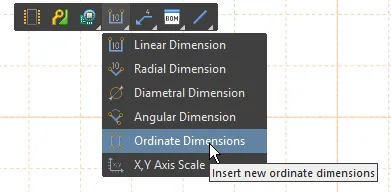
The dimension tools are available on the Active Bar, click and briefly hold the dimension button to open the menu.
Measurement units:
Note that the units system (Metric or Imperial) that applies to a Draftsman document is defined by the Units settings in the Properties panel when in Document Options mode. However, for individual objects such as Linear/Radial Dimensions, Drill/BOM Tables and the Layer Stack Legend, their default units may be preset to Imperial or Metric in the Draftsman – Defaults page of the Preferences dialog. These settings will override the document's base Units setting when a new object of that type is placed.
In turn, the Units used by the placed object can be locally changed through the Units option in the Draftsman Properties panel, when the object is selected.
What objects can a Dimension be attached to?
Each of the Draftsman View types extracts and presents the data that best suits the function of that View. For example, a Board Assembly View is often heavily annotated with dimensions, notes and details about specific components. In an Assembly View the important element for a mounting hole is the drill size and hole center point, not the size of the copper donut that might be present around the hole, or the soldermask expansion value.
From the extracted data, Draftsman makes the following points available as references for dimensions in a Board Assembly View: the centerline and end points of lines and arcs; the edges and edge end points of polygonal shapes; and the center points of circles (holes) and arcs.
The Board Fabrication View is used to show how the copper presents on each fabricated layer. Different data is extracted from the PCB for this type of View, now the copper donut around the mounting hole is more important than the size of the drill hole. This View offers the following points for dimensioning: the centerline and end points of lines and arcs; the edges and edge end points of polygonal shapes; the center of circular shapes (pads, vias and arcs), but not the center of rectangular pad shapes. If a pad has routing to its center then the end point of that routing line will be available, regardless of the pad shape.
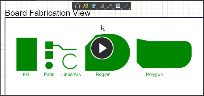
If dimensions created in a Draftsman document are snapped to a primitive that is removed from the PCB document, the dimension objects themselves are not removed and will remain greyed-out on the Draftsman document.
Why Can't I Dimension that Curve?
Polygonal shapes that include curved edges in their design are actually rendered in the PCB editor with the curves replaced by short, straight segments (zoom in close in the PCB editor to see this). This applies to polygons, regions and the board shape. That means if your board shape includes a curved edge, that edge cannot be used to draw a radial dimension in Draftsman, because there is no curved object present.
However, arcs are rendered as a curved object with a radius, so they can be used to draw a radial dimension in Draftsman. If your board has a curved edge that needs to be dimensioned, include a board outline on a mechanical layer in the PCB editor. This outline can be created directly from the board shape if it does not exist. Then enable that mechanical layer in the Draftsman View to be able to add a radial dimension to the curved edge.
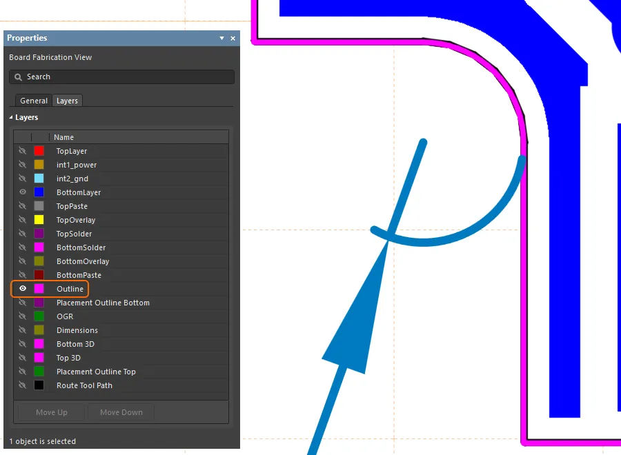
The curve in a board outline is created from short straight segments, include an outline on a mechanical layer to dimension the curve. Hover the cursor over the image to reveal the outline.
Linear Dimension
A Draftsman Linear Dimension is an automated dimensioning object that can be placed between the vertices or edges of Draftsman objects, including Board Views and component objects. This allows a dimension to be placed on the side of an object, between two points on an object, or between nominated sides/vertices of two different objects.
The visual style of the dimension lines and the configuration of the dimension text data can be set in the Properties panel when a placed Linear Dimension is selected.

A variety of Linear Dimensions applied to a Board Assembly View.
To place a Linear Dimension, select Place » Linear Dimension from the main menu or the  icon from the Active Bar dropdown. When the command is launched, the cursor will change to a crosshair, indicating Linear Dimension placement mode. As the cursor is hovered over objects, the object edges and vertex points will be highlighted as orange-colored lines and dots, respectively.
To dimension an object edge (side) the placement steps are:
- Click on a highlighted object edge to place the dimension reference point.
- Move the mouse and click to set the position of the dimension text and its associated extension lines.
To place a dimension between two object edges or vertices, the placement steps are:
- Click on a highlighted object edge or vertex point to place the dimension's first reference point.
- Click on another highlighted object edge/vertex to place the dimension's second reference point.
- Move the mouse and click to set the position of the dimension text and its associated extension lines.
To cancel the placement mode, press Esc or right-click in the design space.

The Linear Dimension can be graphically modified by selecting any part of its graphic representation and dragging the dimension text to a new X/Y location – its associated extension lines will adjust accordingly.

Select and drag the dimension text to a new position.
An existing reference point in a placed Linear Dimension can be moved to a new location through a drag and drop action. When moved, the reference node binds to the new vertex/edge/center and causes the Linear Dimension data (the displayed measurement) to update accordingly, as shown in this animated ![]() demonstration.
demonstration.
Linear Dimension Properties
Radial Dimension
A Draftsman Radial Dimension is an automated dimensioning graphic that applies to a circular board object (hole) or an arc on a Board Assembly View or a Board Fabrication View, or an associated graphic such as a Board Detail View. The text of the placed Radial Dimension reports the radius of the object.
The visual style of the dimension lines and the configuration of the dimension text data can be set in the Properties panel when a placed Radial Dimension is selected.

A variety of Radial Dimensions applied to a Board Assembly View.
To place a Radial Dimension, select Place » Radial Dimension from the main menu or the  icon from the Active Bar dropdown. When the command is launched, the cursor will change to a crosshair, indicating Radial Dimension placement mode. To dimension a hole, object the placement steps are:
- Hover the cursor over circular hole objects in a Board Assembly View. Each hole perimeter will be highlighted as an orange-colored outline.
- Click on a highlighted hole outline to place the dimension target reference.
- Move the mouse and click to set the position of the dimension text and its associated pointer line.
To cancel the placement mode, press Esc or right-click in the design space.
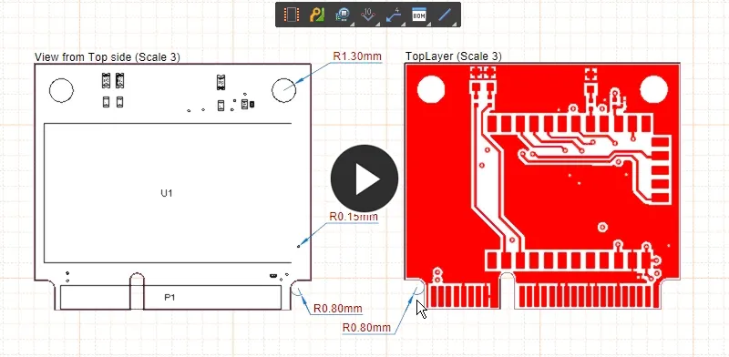
The Radial Dimension can be graphically modified by selecting any part of its graphic representation and then dragging its editing handle new location; its associated extension lines will adjust accordingly.
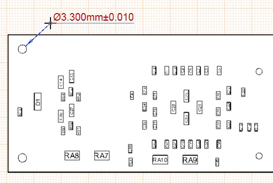
Select and drag the dimension's editing handle to a new position.
Radial Dimension Properties
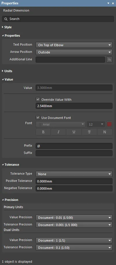
The Radial Dimension mode of the Properties panel.
Style
- Dimension Style – the thickness and style of the Dimension's arrowed line. Use the line weight drop-down menu to choose from a range of line thickness presets and the line pattern menu to choose from a range of line styles. The associated color button (
 ) opens the color selector where the line color can be specified by RGB or HEX value, by freeform selection, or from a range of presets. Note that the slider control sets the color Opacity level where 0% represents full transparency.
Arrow Style
- Head Style – use the drop-down to choose from a range of preset target pointer styles.
- Width – the width of the pointer head, such as an arrow. This setting also defines the diameter of a round head style.
- Length – the length of the pointer head, such as an arrow.
- Full Length – the length of the arrow lines when positioned on the outside of the Dimension line (see Arrow Position below)
Properties
- Text Position – use the drop-down menu to specify the Dimension's text alignment. The text can be attached to the end of the pointer line (leader) or to a horizontal 'elbow' line that terminates the leader line. In both cases it can be set to in-line with or above the associated line.
- Arrow Position – use the drop-down menu to choose the arrow (header) position relative to the targeting leader line. The
Outside option places the arrow on the opposite side of the hole object target point.
- Additional Line – enter text that will be displayed as a second line below the dimension text. Use the associated
 button to toggle its visibility.
Units
- Primary Units – select the main dimension unit type that will be displayed. Use the associated
 buttons to toggle its visibility.
- Dual Units – set the secondary dimension unit type that will be displayed. Use the associated
 buttons to toggle its visibility.
Value
-
Value – the measurement of the selected dimension, as derived by Draftsman. Check the Override Value With box to enter an alternative dimension text in the associated field.
Note that Draftsman will automatically detect (and convert if necessary) a dimension that has been manually entered in the Properties panel with a specific Units suffix – such as mm or mil. When a dimension is entered without a suitable suffix, the figure is assumed to be in the Units that are configured for the document or object.
- Font – sets the displayed font used for the Dimension text string.
- Use Document Font checkbox selected – the font used is that defined by the document options. See the Document Font entry in General section of the Properties panel when in Document Options mode.
- Use Document Font not selected – use the Font drop-down menus to choose the desired font type and size and select the lower buttons to enable text attributes. The associated color button (
 ) opens the color selector where the font color can be specified by RGB or HEX value, by freeform selection, or from a range of presets. Note that the slider control sets the color Opacity level where 0% represents full transparency.
- Prefix – enter a text string/character that will be displayed before the dimension text.
- Suffix – enter a text string/character that will be displayed after the dimension text.
Tolerance
- Tolerance Type – use the drop-down menu to enable and set the type of displayed tolerance (the expected or acceptable variation in the target dimension):
Symmetric – sets the positive and negative tolerance to the same value, which is determined by the Positive Tolerance field entry.Bilateral – allows the specification of independent positive and negative tolerance values as defined by their respective Positive/Negative Tolerance field entries (see below).Limit – sets the tolerance display type to show the expected or acceptable value that the dimension may deviate.
- Positive Tolerance – enter a value for the acceptable or expected worst case increase of the dimension.
- Negative tolerance – enter a value for the acceptable or expected worst case decrease of the dimension.
Precision
Specifies the numerical precision (number of significant digits to the right of the decimal point, with the last digit rounded) for the dimension text.
- Primary Units – use the Value and Tolerance Precision drop-down menus to choose the numerical rounding for the Primary (main) dimension Value/Tolerance text.
- Dual Units – use the Value and Tolerance Precision drop-down menus to choose the numerical rounding for the Dual (secondary) dimension Value/Tolerance text.
Diametral Dimension
The Diametral Dimension is an automated dimensioning graphic that applies to circular hole objects in a Board Assembly View. The visual style of the dimension lines and the configuration of the dimension text data can be set in the Properties panel when a placed Diametral Dimension is selected. The Diametral Dimension can be graphically modified by selecting any part of its graphic representation and then dragging its editing handle to the new location; its associated extension lines will adjust accordingly. The visual style of the dimension lines and the configuration of the dimension text data can be set in the Properties panel, when a placed Diametral Dimension is selected.
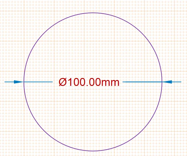
A variety of Diametral Dimensions applied to a Board Assembly View.
To place a Diametral Dimension object, select Place » Diametral Dimension from the main menu or the  icon from the Active Bar dimension dropdown. When the command is launched, the cursor will change to a crosshair, indicating Diametral Dimension placement mode. To dimension a hole object the placement steps are:
- Hover the cursor over circular hole objects in a Assembly View. Each hole perimeter will be highlighted as an orange colored outline.
- Click on a highlighted hole outline to place the dimension target reference.
- Move the mouse and click to set the position of the dimension text and its associated pointer line.
To cancel the placement mode, press Esc or right-click in the design space.
The size, and therefore, number of holes that will be included in a Board Assembly View is determined by the
Display Holes setting and its associated
Minimum Diameter field in the
Assembly View Properties – see the panel's
Properties section.
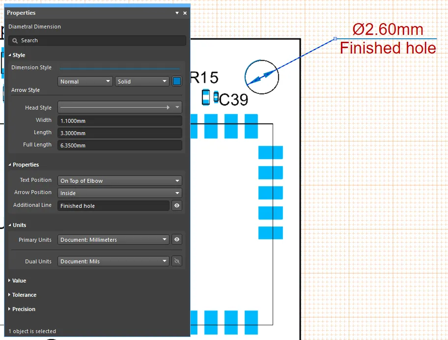
Use the Diametral Dimension tool to show the diameter of a hole in an Assembly View.
Diametral Dimension Properties
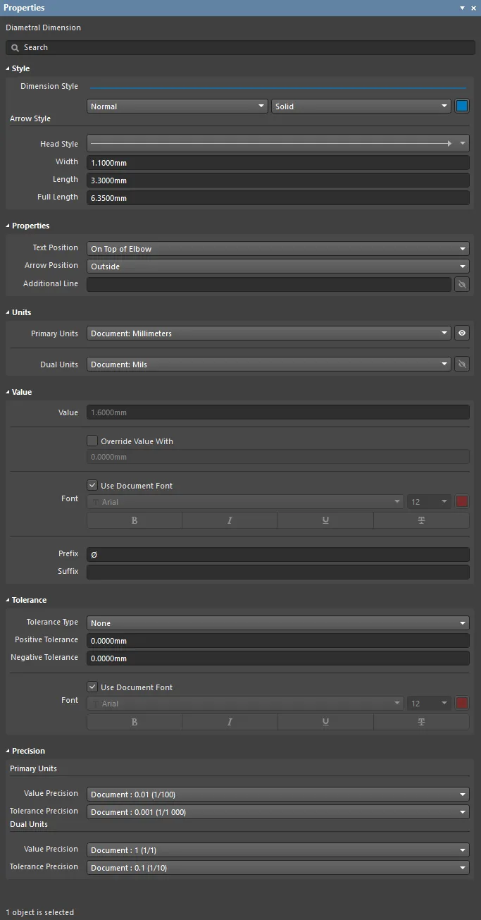
The Diametral Dimension mode of the Properties panel.
Style
- Dimension Style – the thickness and style of the Dimension's arrowed line. Use the line weight drop-down menu to choose from a range of line thickness presets and the line pattern menu to choose from a range of line styles. The associated color button (
 ) opens the color selector where the line color can be specified by RGB or HEX value, by freeform selection, or from a range of presets. Note that the slider control sets the color Opacity level where 0% represents full transparency.
Arrow Style
- Head Style – use the drop-down to choose from a range of preset target pointer styles.
- Width – the width of the pointer head, such as an arrow. This setting also defines the diameter of a round head style.
- Length – the length of the pointer head, such as an arrow.
- Full Length – the length of the arrow lines when positioned on the outside of the Dimension line (see Arrow Position below)
Properties
- Text Position – use the drop-down menu to specify the Dimension's text alignment. The text can be attached to the end of the pointer line (leader) or to a horizontal 'elbow' line that terminates the leader line. In both cases it can be set to in-line with or above the associated line.
- Arrow Position – use the drop-down menu to choose the arrow (header) position relative to the targeting leader line. The
Outside option places the arrow on the opposite side of the hole object target point.
- Additional Line – enter text that will be displayed as a second line below the dimension text. Use the associated
 button to toggle its visibility.
Units
- Primary Units – select the main dimension unit type that will be displayed. Use the associated
 button to toggle its visibility.
- Dual Units – set the secondary dimension unit type that will be displayed. Use the associated
 button to toggle its visibility.
Value
- Value – the measurement of the selected dimension. Check the Override Value With box to enter an alternative dimension text in the associated field.
- Font – sets the displayed font used for the Dimension text string.
- Use Document Font checkbox selected – the font used is that defined by the document options. See the Document Font entry in General section of the Properties panel when in Document Options mode.
- Use Document Font not selected – use the Font drop-down menus to choose the desired font type and size and select the lower buttons to enable text attributes. The associated color button (
 ) opens the color selector where the font color can be specified by RGB or HEX value, by freeform selection, or from a range of presets. Note that the slider control sets the color Opacity level where 0% represents full transparency.
- Prefix – enter a text string/character that will be displayed before the dimension text.
- Suffix – enter a text string/character that will be displayed after the dimension text.
Tolerance
- Tolerance Type – use the drop-down menu to enable and set the type of displayed tolerance (the expected or acceptable variation in the target dimension):
Symmetric – sets the positive and negative tolerance to the same value, which is determined by the Positive Tolerance field entry. Bilateral – allows the specification of independent positive and negative tolerance values as defined by their respective Positive/Negative Tolerance field entries (see below).Limit – sets the tolerance display type to show the expected or acceptable value that the dimension may deviate.
- Positive Tolerance – enter a value for the acceptable or expected worst case increase of the dimension.
- Negative tolerance – enter a value for the acceptable or expected worst case decrease of the dimension.
- Font – sets the displayed font used for the Dimension text string.
- Use Document Font checkbox selected – the font used is that defined by the document options. See the Document Font entry in General section of the Properties panel when in Document Options mode.
- Use Document Font not selected – use the Font drop-down menus to choose the desired font type and size and select the lower buttons to enable text attributes. The associated color button (
 ) opens the color selector where the font color can be specified by RGB or HEX value, by freeform selection, or from a range of presets. Note that the slider control sets the color Opacity level where 0% represents full transparency.
Precision
Specifies the numerical precision (number of significant digits to the right of the decimal point, with the last digit rounded) for the dimension text.
- Primary Units – use the Value and Tolerance Precision drop-down menus to choose the numerical rounding for the Primary (main) dimension Value/Tolerance text.
- Dual Units – use the Value and Tolerance Precision drop-down menus to choose the numerical rounding for the Dual (secondary) dimension Value/Tolerance text.
Angular Dimension
A Draftsman Angular Dimension is an automated dimensioning graphic that reports the relative angle between two object faces (or a Center Mark crosshair line) on a Board Assembly View or a Board Fabrication View, or an associated view such as a Board Detail View. The automated dimensioning graphic reports the relative angle between two object faces, such as the sides/edges of a component or board. The dimension graphic style and its text content can be set to a range formats in the Properties panel when a placed Angular Dimension is selected.
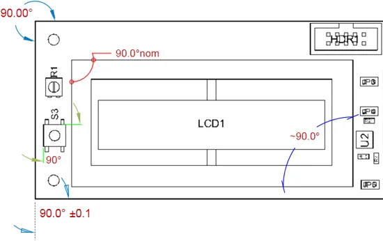
A variety of Angular Dimensions applied to a Board Assembly View.
To place an Angular Dimension, select Place » Angular Dimension from the main menu or the  icon from the Active Bar dropdown. When the command is launched, the cursor will change to a crosshair indicating Angular Dimension placement mode. To dimension the angle between two object faces, the placement steps are:
- Hover the cursor over an object face edge (or Center Mark crosshair line) and then click the highlighted line to select the first angle reference.
- Hover the cursor over another object edge/line and then click the highlighted line to select the second angle reference.
- Move the mouse then click to set the position of the dimension text and the style of the angular dimension lines (see Graphical Editing below).
To cancel the placement mode, press Esc or right-click in the design space.
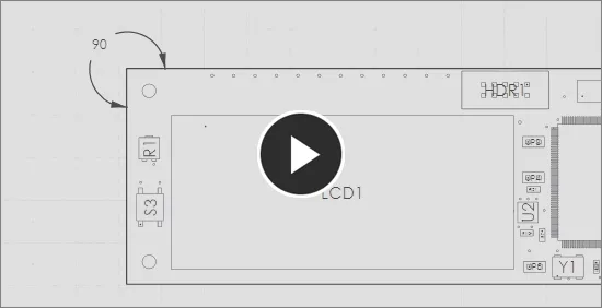
The Angular Dimension can be graphically modified by selecting any part of its graphic representation and then dragging its editing handle to a new location. During the repositioning (and during initial placement of the dimension) the arrowed dimension lines will automatically adjust their drawing mode and/or add extension lines to best match the current text position.

Select and drag the dimension's editing handle to a new position.
Angular Dimension Properties
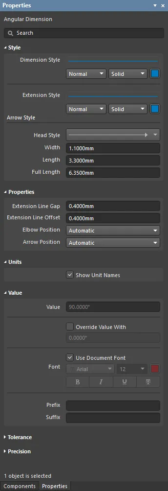
The Angular Dimension mode of the Properties panel.
Style
- Dimension Style – the thickness and style of the Dimension's arrowed lines. Use the line weight drop-down menu to choose from a range of line thickness presets, and the line pattern menu to choose from a range of line styles. The associated color button (
 ) opens the color selector where the line color can be specified by RGB or HEX value, by freeform selection or from a range of presets. Note that the slider control sets the color Opacity level, where 0% represents full transparency.
- Extension Style – the thickness and style of the Dimension's extension lines. Use the line weight drop-down menu to choose from a range of line thickness presets and the line pattern menu to choose from a range of line styles as outlined above. Note that Draftsman will automatically add extension lines as required when the dimension is graphically modified.The associated color button (
 ) opens the color selector where the line color can be specified by RGB or HEX value, by freeform selection or from a range of presets. Note that the slider control sets the color Opacity level, where 0% represents full transparency.
Arrow Style
- Head Style – select the drop-down to choose from a range of preset dimension pointer styles.
- Width – the width of the pointer head, such as an arrow. This setting also defines the diameter of a round head style.
- Length – the length of the pointer head, such as an arrow.
- Full Length – the overall length of the arrow lines, when positioned on the outside of the extension lines (see Arrow Position, below)
Properties
- Extension Line Gap – set the spacing between the dimension target points and the beginning of the extension lines.
- Extension Line Offset – set the distance that the extension lines will protrude beyond the arrowed dimension line.
- Elbow Position – set the horizontal line at the end of the dimension (if present) to protrude to the
Left or Right. Note that Draftsman will automatically add an elbow line as required when the dimension is graphically modified.
- Arrow Position – select the dimension arrow pointers to be
Inside or Outside the dimension, relative to the extension lines. Note that Draftsman will automatically change the arrow position as required when the dimension is graphically modified.
Units
- Show Unit Names – check to display the measurement units, namely the degrees character symbol, as the dimension text suffix.
Value
- Value – the measurement of the selected dimension, as derived by Draftsman. Check the Override Value With box to enter an alternative dimension text in the associated field.
- Font – sets the displayed font used for the Dimension text string.
- Use Document Font checkbox selected – the font used is that defined by the document options. See the Document Font entry in General section of the Properties panel when in Document Options mode.
- Use Document Font not selected – use the Font drop-down menus to choose the desired font type and size, and select the lower buttons to enable text attributes. The associated color button (
 ) opens the color selector, where the font color can be specified by RGB or HEX value, by freeform selection, or from a range of presets. Note that the slider control sets the color Opacity level, where 0% represents full transparency.
- Prefix – enter a text string that will be displayed before the dimension text.
- Suffix – enter a text string that will be displayed after the dimension text.
Tolerance
- Tolerance Type – use the drop-down menu to enable and set the type of displayed tolerance (the expected or acceptable variation in the target dimension):
Symmetric – sets the positive and negative tolerance to the same value, which is determined by the Positive Tolerance field entry. Bilateral – allows the specification of independent positive and negative tolerance values, as defined by their respective Positive/Negative Tolerance field entries (see below).Limit – sets the tolerance display type to show the expected or acceptable value that the dimension may deviate.
- Positive Tolerance – enter a value for the acceptable or expected worst case increase of the dimension.
- Negative tolerance – enter a value for the acceptable or expected worst case decrease of the dimension.
Precision
Specifies the numerical precision (number of significant digits to the right of the decimal point, with the last digit rounded) for the dimension text.
- Value Precision – use the drop-down menu to choose the numerical rounding for the dimension Value text.
- Tolerance Precision – use the drop-down menu to choose the numerical rounding for dimension Tolerance text (if enabled).
Ordinate Dimension
A Draftsman Ordinate Dimension is an automated dimensioning object that is composed of multiple linear dimension elements that are relative to a specified reference point. The dimensions in the ordinate set can be placed on the outlines edges or vertices of Draftsman objects in a Board Assembly View (or its Section View), including the board itself. The indicated dimensions are effectively cumulative as they are placed at increasing distances from the nominated reference point, and can be placed on the outlines edges or vertices of a placed board view or its constituent objects.
The visual style of the dimension lines and the configuration of the dimension text can be set in the Properties panel when a placed Ordinate Dimension is selected.
 A variety of Ordinate Dimensions applied to a Board Assembly View.
To place an Ordinate Dimension set, select Place » Ordinate Dimension from the main menu or the  icon from the Active Bar dropdown. When the command is launched, the cursor will change to a crosshair, indicating Ordinate Dimension placement mode. As the cursor is hovered over objects, the object edges and vertex points will be highlighted as orange-colored lines and dots, respectively.
The Ordinate Dimension placement steps are:
- Hover the cursor over the drawing view until the desired (reference) point or object edge is highlighted.
- Click to select this as the dimension reference point then move the cursor and click to set the extension position and angle.
- Continue selecting points to create the full series of dimensions that are relative to the first placed reference point.
To cancel the placement mode, press Esc or right-click in the design space. Dimensions can be added or removed from the ordinate set after it has been placed – see Graphical Editing below.

A series of Ordinate Dimensions are treated as one object, but individual entries can be added and removed.
When a set of Ordinate Dimensions has been selected in the design space, by clicking on any part of its graphic representation, it can be graphically modified in the following ways:
- Drag the dimension's lines or text to a new location on the same axis. In this editing mode, the set of dimensions behave as one object and can be moved as a single entity.
- To add a new dimension to the ordinate set, select another highlighted object location on the drawing view.
- To remove an individual dimension from the ordinate set, click on its node handle.
 Select and drag the dimension set to a new position, or add/remove individual dimensions.
The set of dimensions behave as one object, and can, therefore, be moved as a single entity or edited as an object in the Draftsman
Properties panel. However, note that individual dimensions may be added or removed when the Ordinate Dimension object is selected.
Ordinate Dimension Properties
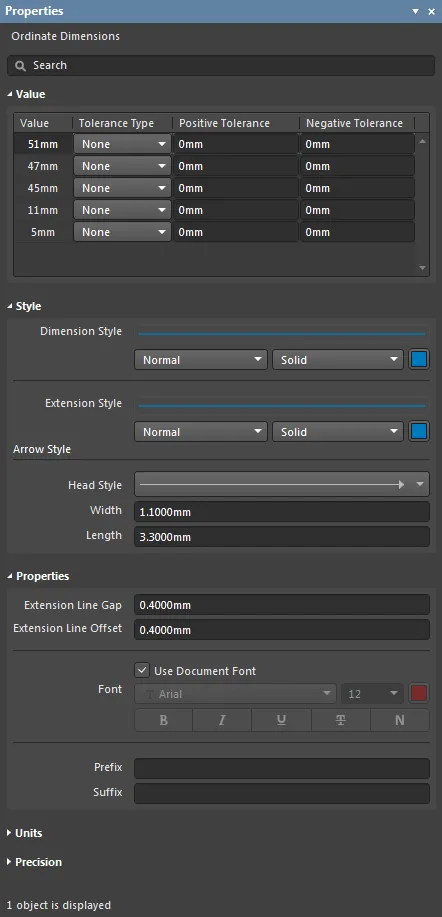
The Ordinate Dimensions mode of the Properties panel.
Value
This is a table that lists each dimension within the ordinate set, along with its associated tolerance settings.
- Value – the measurement of an individual dimension in the ordinate set as derived by Draftsman.
- Tolerance Type – use the drop-down menu to enable and set the type of displayed tolerance for the dimension (the expected or acceptable variation in the dimension):
Symmetric – sets the positive and negative tolerance to the same value, which is determined by the Positive Tolerance field entry.Bilateral – allows the specification of independent positive and negative tolerance values as defined by their respective Positive/Negative Tolerance field entries (see below).Limit – sets the tolerance display type to show the expected or acceptable value that the dimension may deviate.
- Positive Tolerance – enter a value for the acceptable or expected worst case increase of the dimension.
- Negative tolerance – enter a value for the acceptable or expected worst case decrease of the dimension.
Style
- Dimension Style – the thickness and style of the Dimension's arrowed lines. Use the line weight drop-down menu to choose from a range of line thickness presets and the line pattern menu to choose from a range of line styles. The associated color button (
 ) opens the color selector where the line color can be specified by RGB or HEX value, by freeform selection, or from a range of presets. Note that the slider control sets the color Opacity level where 0% represents full transparency.
- Extension Style – the thickness and style of the Dimension extension lines. Use the line weight drop-down menu to choose from a range of line thickness presets and the line pattern menu to choose from a range of line styles as outlined above.
Arrow Style
- Head Style – select the drop-down to choose from a range of preset target pointer styles.
- Width – the width of the pointer head, such as an arrow. This setting also defines the diameter of a round head style.
- Length – the length of the pointer head, such as an arrow.
Properties
- Extension Line Gap – set the spacing between the dimension target points and the beginning of the extension lines.
- Extension Line Offset – set the distance that the extension lines will protrude beyond the arrowed dimension lines.
- Font – sets the displayed font used for the Dimension text strings.
- Use Document Font checkbox selected – the font used is that defined by the document options. See the Document Font entry in General section of the Properties panel when in Document Options mode.
- Use Document Font not selected – use the Font drop-down menus to choose the desired font type and size, and select the lower buttons to enable text attributes. The associated color button (
 ) opens the color selector where the font color can be specified by RGB or HEX value, by freeform selection, or from a range of presets. Note that the slider control sets the color Opacity level where 0% represents full transparency.
- Prefix – enter a text string that will be displayed before the dimension text.
- Suffix – enter a text string that will be displayed after the dimension text.
Units
- Primary Units – select the main dimension unit type that will be displayed. Use the associated
 button to toggle the unit's visibility.
- Dual Units – set the secondary dimension unit type that will be displayed. Use the associated
 button to toggle the unit's visibility.
Precision
Specifies the numerical precision (number of significant digits to the right of the decimal point, with the last digit rounded) for the dimension text.
- Primary Units – use the Value and Tolerance Precision drop-down menus to choose the numerical rounding for the Primary (main) dimension Value/Tolerance text.
- Dual Units – use the Value and Tolerance Precision drop-down menus to choose the numerical rounding for the Dual (secondary) dimension Value/Tolerance text.
X,Y Axis Scale
The X,Y Axis Scale object can be used to place a reference scale against any type of View object. Various properties of the object can be customized, including the thickness, stylistic design of the line styles, and font choice. The visual style of the axis scale and the configuration of the axis scale text data can be set in the Properties panel when a placed X, Y Axis Scale is selected.
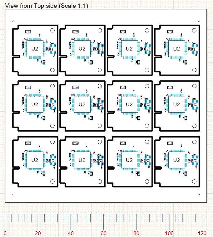
A variety of X, Y Axis Scale applied to a Board Assembly View.
To place an X,Y Axis Scale, select Place » X,Y Axis Scale from the main menu or select the  icon from the Active Bar dimension dropdown. Hover the cursor over the required object in the View and the cursor will change to an orange dot, indicating a valid reference point. Click to attach the zero end of the scale. Reposition the cursor and click a second time to attach the far end of the scale; then move the cursor to set the distance between the referenced objects and the Axis Scale, click a third time to place the scale.
The X, Y Axis Scale object can be graphically modified by selecting any part of its graphic representation and then dragging its editing handle towards or away from the Board Assembly View object – its associated extension lines will adjust accordingly.
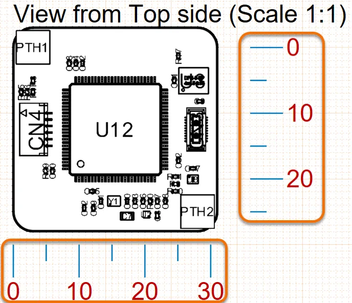
Select and drag the dimension's editing handle to a new position.
X,Y Axis Scale Properties
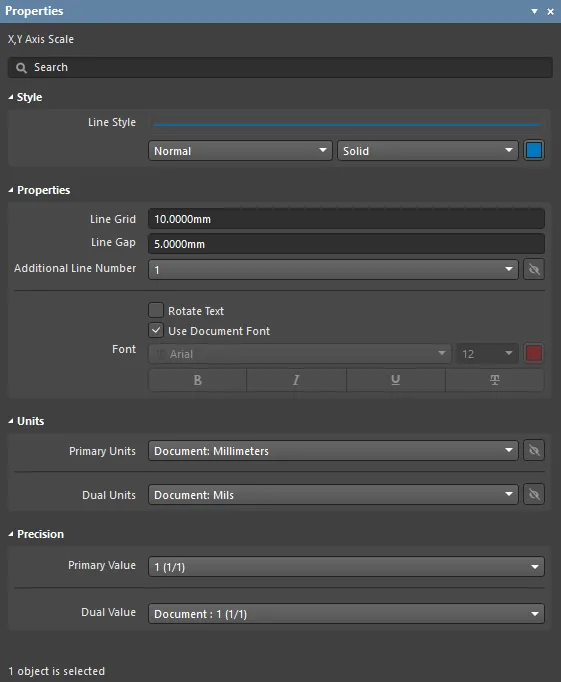
The X, Y Axis Scale mode of the Properties panel.
Style
- Line Style - the thickness and style of the axis scale's lines. Use the line weight drop-down menu to choose from a range of line thickness presets and the line pattern menu to choose from a range of line styles. The associated color button (
 ) opens the color selector where the line color can be specified by RGB or HEX value, by freeform selection, or from a range of presets. Note that the slider control sets the color Opacity level where 0% represents full transparency.
Properties
- Line Grid - the current grid distance value, which determines the distance of ticks featured between numeric values.
- Line Gap - the current gap distance value, which determines the distance between the numeric values and the axis scale line.
- Additional Line Number - click the drop-down to select the text that will be displayed as a second line below the dimension text. Use the associated
 button to toggle its visibility.
- Rotate Text - check this box to rotate the text counterclockwise in increments of 90°.
- Use Document Font checkbox selected – the font used is that defined by the document options. See the Document Font entry in General section of the Properties panel when in Document Options mode.
- Use Document Font not selected – use the drop-down menus to choose the desired font type and size and select the lower buttons to enable text attributes. The associated color button (
 ) opens the color selector where the font color can be specified by RGB or HEX value, by freeform selection, or from a range of presets. Note that the slider control sets the color Opacity level, where 0% represents full transparency.
- Font – sets the font used for the axis scale.
- Use Document Font checkbox selected – the font used is that defined by the document options. See the Document Font entry in General section of the Properties panel when in Document Options mode.
- Use Document Font not selected – use the drop-down menus to choose the desired font type and size and select the lower buttons to enable text attributes. The associated color button (
 ) opens the color selector where the font color can be specified by RGB or HEX value, by freeform selection, or from a range of presets. Note that the slider control sets the color Opacity level, where 0% represents full transparency.
Units
- Primary Units – select the main dimension unit type that will be shown in the table. Use the associated
 button to toggle the unit's visibility.
- Dual Units – set the secondary dimension unit type that will be shown in the table. Use the associated
 button to toggle the unit's visibility.
Precision
Specifies the numerical precision (number of significant digits to the right of the decimal point, with the last digit rounded) for the layer specifications.
- Primary Units – use the Value Precision drop-down menu to choose the numerical rounding for the Primary (main) layer dimension table entries.
- Dual Units – use the Value Precision drop-down menu to choose the numerical rounding for the Dual (secondary) layer dimension table entries, if enabled.
Geometric Dimensioning and Tolerances
Draftsman includes the capability to place and configure industry-standard Geometric Dimensioning and Geometric Tolerances symbolic elements that define the manufacturing properties of objects included in a drawing.
Also used in most advanced MCAD applications, the specialized information provided by the placed geometric symbols stipulates the allowable imperfections in the manufacture of physical objects. The geometric definition elements that can be added to Draftsman documents are derived from standards developed by the American Society of Mechanical Engineers (ASME) – specifically, the ASME Y14.5-2009 Dimension and Tolerancing standard. Many other standards and guidelines exist for geometric engineering definitions, including a large number of conceptually specific documents from the International Organization for Standardization (ISO).
► See Geometric dimensioning and tolerancing for overview information and reference links.
In terms of Draftsman engineering documents, the symbol-based Dimensioning and Tolerancing information is incorporated into a drawing by the placement of two types of objects:
- Datum Feature symbols – Identification objects that can be attached to a line, point or axis of a physical feature in a drawing, such as the edge of the board, component or hole.
- Feature Control Frames – Information objects that can be attached to a drawing feature, which include multiples of symbolic data that specify the mechanical manufacturing constraints for the feature.
Both of the above drawing objects can be positioned freely in the document, or (normally) attached to a feature such as an edge. In the same way in which other Drawing Annotations are placed in Draftsman, such as Surface Finish symbols, the geometric definition symbols are attached by clicking on a highlighted line in the drawing and then clicking again to place the symbol.
Datum Feature
A Datum Feature is a graphic identification object that can be attached to a line, point, or axis of a physical feature in a drawing, such as the edge of board, component, or hole. It acts as a reference on that drawing object so that relative dimension tolerances included in Feature Control Frames can refer to this and other placed datum. When added to the mechanical elements in a Draftsman drawing view, the combined information represented by Feature Control Frames and their related Datum references can fully describe the acceptable manufacturing constraints for those physical elements.
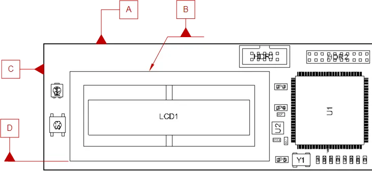
A number of Datum Feature symbols attached to the surface edges of objects in a Board Assembly View.
Place a Datum Feature on a drawing using the Place » Datum Feature menu command or by selecting the  icon from the Annotations drop-down on the Active Bar. After launching the command, the cursor will change to a cross-hair and the editor will enter Datum placement mode. Placement is made by performing the following actions:
- Position the cursor over a highlighted object edge then click to attach the Datum Feature to that object face.
- Move the cursor to set the position of the Datum label then click again to complete placement.
The graphical method of editing allows a placed Datum object to be selected in the design space and its edge attachment point or label location changed. When a Datum Feature object is selected, editing handles/nodes become available at its attachment and header label points.
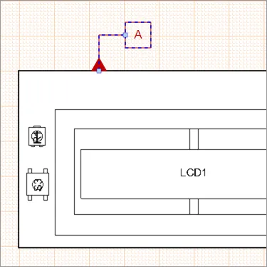
A selected Datum Feature with its two positioning nodes
- Click and drag the label node to reposition it on the drawing document.
- Click and drag the edge attachment node to reposition it along the selected object face. An extension line is added when the attachment point is moved beyond the boundary of the object face.
The Datum Feature is identified by its Label entry in the Properties panel so that relative dimension tolerances included in Feature Control Frames can refer to this and other placed datum.
Datum Feature Properties
Feature Control Frame
A Feature Control Frame is a graphic information object that can be placed on a Draftsman document sheet to define the manufacturing constraints of the physical feature to which it is attached, such as an object face or machined cutout/hole.
The tabular frame object applies a specialized range of symbols, tolerance values and location references to specify acceptable manufacturing imperfections as defined by the ASME Y14.5-2009 Dimension and Tolerancing standard. Draftsman Datum Feature objects are used as reference locations in placed Feature Control Frames. Attached machining tolerances, such as the 'straightness' of a feature for example, apply to the specified drawing object face. Attached Dimension tolerances by comparison (such as 'position') are generally specified as relative to one or more placed Datum. When added to the mechanical elements in a Draftsman drawing view, the combined information represented by Feature Control Frames and their related Datum references can fully describe the acceptable manufacturing constraints for those physical elements. See Applied Geometric Tolerances for information on a number of basic examples.
The graphic style and dimensioning/tolerancing attributes for a placed Feature Control Frame are definable in the Properties panel. Multiple definition rows may be added to the frame in the Selected Element region of the Properties panel.
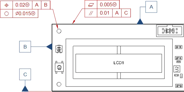
Feature Control Frame objects attached to a hole and an edge in a Board Assembly View. The three Datum Feature objects are used as reference locations.
Place a Feature Control Frame on a drawing using the Place » Feature Control Frame menu command or by selecting the  icon from the Annotations drop down on the Active Bar, and attach it to a drawing feature as outlined above, or place it free space. After launching the command, the cursor will change to a cross-hair and the editor will enter Feature Control Frame placement mode. Placement is made by performing the following actions:
- Position the cursor at the required point within the drawing; typically this will be a feature such as an edge. In this case, position at a point where the drawing element is highlighted (an edge or a point). With the cursor in position, click to attach the feature control frame to that feature.
- Move the cursor to set the position of the frame then click again to complete placement.
The graphical method of editing allows a placed Feature Control Frame to be selected in the design space and its object attachment point or frame location changed. When the Feature Control Frame object is selected, editing handles/nodes become available at its attachment and frame points.
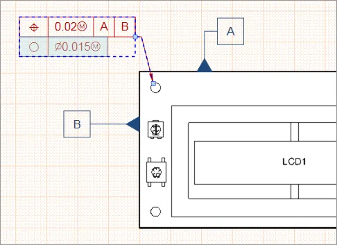
A selected Feature Control Frame with its two positioning nodes.
- Click and drag the tabular frame to reposition it on the drawing document.
- Click and drag the edge attachment node to reposition it on the selected object face. An extension line is added when the attachment point is moved beyond the boundary of the object face.
The information it conveys, presented in symbols, modifiers and numeric values, is entered in the Properties panel.
Feature Control Frame Properties
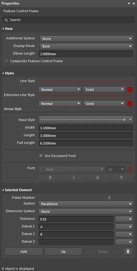
The Feature Control Frame mode of the Properties panel
View
- Additional Symbol – use the drop-down menu to select optional header graphic attributes that specify if the dimension/tolerance applies to the local area or to the complete physical item.
- Display Mode – sets the style of connection line between the frame and the object surface reference point.
- Elbow Length – sets the length of the horizontal part of the connection line when Display Mode is set to the
Bent option.
- Composite Feature Control Frame – when checked, a single definition symbol applies to all row data in the Feature Control Frame.
Styles
- Line Style – the thickness and style of the line used to render the tabular frame and its leader line. Use the line weight drop-down menu to choose from a range of line thickness presets, and the line pattern menu to choose from a range of line styles. The associated color button (
 ) opens the color selector, where the line color can be specified by RGB or HEX value, by freeform selection, or from a range of presets. Note that the slider control sets the color Opacity level, where 0% represents full transparency.
- Extension Style – the thickness and style of the line that automatically extends from an object edge when a Feature Control Frame attachment point is moved beyond the object's bounds. Use the line weight drop-down menu to choose from a range of line thickness presets, and the line pattern menu to choose from a range of line styles. The associated color button (
 ) opens the color selector, where the line color can be specified by RGB or HEX value, by freeform selection, or from a range of presets. Note that the slider control sets the color Opacity level, where 0% represents full transparency.
Arrow Style
- Head Style – select the drop-down to choose from a range of preset pointer styles (headers).
- Width – the width of the target pointer head, such as an arrow. This setting also defines the diameter of a round head style.
- Length – the length of the pointer head, such as an arrow.
- Full Length – the length of the arrow lines when positioned on the outside of the feature control frame.
- Use Document Font checkbox – when checked, the font used for the Feature Control Frame data is that defined by the document options. See the Document Font entry in General section of the Properties panel when in Document Options mode.
- Font (applies when Use Document Font not selected) – use the Font drop-down menus to choose the desired font type and size and select the lower buttons to enable text attributes. The Feature Control Frame graphic will proportionally scale with the font size. The associated color button (
 ) opens the color selector, where the line color can be specified by RGB or HEX value, by freeform selection, or from a range of presets. Note that the slider control sets the color Opacity level, where 0% represents full transparency.
Selected Element
Applies to the data row in the Feature Control Frame that is currently selected. Click within the bounds of a frame row (element) to select it.
- Frame Number – the number of the currently selected element row in the Feature Control Frame.
- Symbol – the graphic symbol, as defined in the
ASME Y14.5-2009 Dimension and Tolerancing standard, that indicates type of dimension or tolerance information in the selected frame row.
- Dimension Symbol – the type of relative dimensioning that is defined by the row data (such as machined Square or Diameter based cutouts).
- Tolerance – the acceptable variation (tolerance) in the row's specified numerical dimension. Use the associated drop-down menu (
 ) to select from a range of coded symbol modifiers, as defined by the
 ASME Y14.5-2009 Dimension and Tolerancing standard.
- Datum 1 – reference location for the selected dimension/tolerance, as specified by the entered Datum Feature label. Use the associated drop-down menu to select from a range of coded symbol modifiers.
- Datum 2 – a relative reference location for the selected dimension/tolerance, as specified by the entered Datum Feature label – for example, a parallel surfaces specification might apply to the faces at Datum 1 relative to Datum 2. Use the associated drop-down menu to select from a range of coded symbol modifiers.
- Datum 3 – an additional relative reference location for the selected dimension/tolerance, as specified by the entered Datum Feature label. Use the associated drop-down menu to select from a range of coded symbol modifiers.
- Add button – click to add a new data row (element) to the Feature Control Frame. Use the
 button to remove the currently selected element.
- Up / Down buttons – click to move the selected element up or down by one count in the frame's row order.
Applied Geometric Tolerances
When added to the mechanical elements in a Draftsman drawing view, the combined information represented by Feature Control Frames and their related Datum references can fully describe the acceptable manufacturing constraints for that physical element.
In the example drawing view shown below, dimensions have been added, Datum Feature references attached to the three visible board edges, and Feature Control Frames applied to the top edge and two mounting holes. The Feature Control Frames have multiple elements added, which appear as a sequence of (selectable) rows – note the Add, Delete etc., buttons in the Selected Element area of the Properties panel.
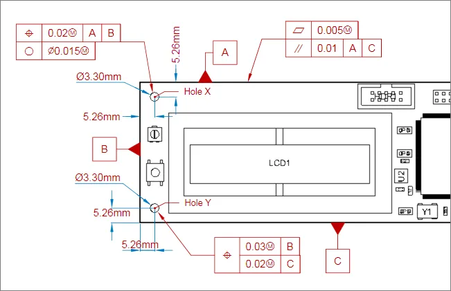
The symbols and formatting used in the various Feature Control Frames are fully described in the ASME standard, however, an overview of the examples shown above is as follows:
- Frame attached to edge A
- First element (top row) – stipulates the flatness tolerance (acceptable deviation in the surface) for the board edge.
- Second element – stipulates parallel tolerance (acceptable distance, and therefore angle deviance) between sides A and C.
- Frame attached to Hole X
- First element (top row) – stipulates the hole position tolerance (acceptable positional error) relative to both Datum A and Datum B.
- Second element – stipulates the roundness tolerance (acceptable diameter variance) for the hole.
- Frame attached to Hole Y: A Composite Feature Control Frame (as selected by the related checkbox in the Properties panel)
- Symbol for this frame (first column) – defines this Frame as positional information, for all elements (rows).
- First sub element – stipulates the tolerance (acceptable error) for Hole Y relative to Datum B.
- Second sub element – stipulates the tolerance (acceptable error) for Hole Y relative to Datum C.