Each Item in a connected Workspace is comprised of a series of revisions, with a new revision used to accommodate new data, each time that data is modified and committed/uploaded/released. The revision, therefore, reflects the progress of the Item as it undergoes changes. Or to say that the other way around, if the data entity represented by the Item changes, the revision must be incremented to reflect that.
For any revision of an Item, it is also important to reflect the current state of that revision – what stage of its 'life' it has reached. This status is referred to as the Item Revision's Lifecycle.
The lifecycle allows a company to manage the Item from a business perspective, and in accordance with company policies and practices. With this lifecycle information, people that need to use an Item in a Workspace – from a designer contemplating reuse of a released design 'building block', to the supply chain needing the data to fabricate and assemble a board – are able to see, at-a-glance, what stage a revision of an Item has reached in its 'life' and therefore what it can be safely used for.
Modeling the Lifecycle
While different organizations may choose to model or label the lifecycle of design items slightly differently, they will all follow a similar theme. For example, the general cycle of a product’s life will be something like: it starts as a design idea, then becomes a prototype, then goes into production, then at some point becomes obsolete and is no longer made or sold.
Using lifecycle status information on every component of a design helps to ensure that a design can only be promoted to a higher state if that new state is less than or equal to the lowest-state component within the design. For example, if a design is ready to move into production, it should only be allowed to do so if all components within it are also in production – i.e. components that are still In Prototype (or New From Design) must be promoted to In Production before the design as a whole can be promoted to that level.
In many cases, the revisions of design Items will progress through the various lifecycle states linearly however it should not be assumed that this is the only path that can be taken. For example, some Item revisions may end up being abandoned before they have even reached the prototyping stage. In a connected Workspace, the allowable states that an Item's revision can move between are defined by a Transition table included in the lifecycle definition.
A connected Workspace supports two levels of lifecycle management: Simple or Advanced. These essentially determine the style of management, upon which the lifecycle definitions themselves are then built. For a lifecycle definition based on the simple management style, only states and state transitions are involved. For a lifecycle definition based on the advanced management style, states can be further clustered into defined stages.
Both the simple and advanced lifecycle management styles support the same set of States (the different points at which an Item's revision can exist in its life), and Transitions (how an Item's revision moves between those states).
States, Stages, and Transitions
Related page: Accessing the Detailed Item View
Each point in an Item Revision's lifecycle is referred to as a State, for example In Production. When an Item's revision changes state it is referred to as a Transition, which can only be to another state.
Lifecycle definitions based on the advanced management style support states being clustered into Stages. Stages allow labels to be created that identify where an Item's revision is in its development. For example, it could be in Design, or in Prototype, or in Production.

An example lifecycle definition whose states are clustered into three stages.
The image below shows a snippet from the detailed Item view for an Item that employs a 3-level Revision Naming Scheme: Model, Prototype, and Revision. Each model is shown as a separate block. Within a model, each prototype is a sub-block. Below each prototype are the revisions of that model/prototype, then within each revision are the different states that the revision existed in.
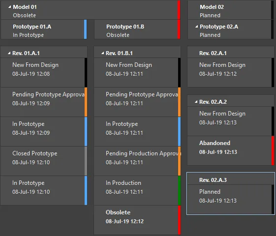
Example lifecycle states for various revisions of an Item.
Stages in an advanced-style lifecycle definition can also be linked to the revision levels of the employed revision naming scheme, creating a horizontal dimension to the presentation of an Item's lifecycle, that meshes with the Item's revision – see the
Linking Stages to Levels of the Revision Naming Scheme section for more details.
Default Lifecycle Definitions
A connected Workspace provides eight default lifecycle definitions. These default definitions can be used 'as is', or modified to suit company (or personal) requirements. New, custom definitions can also be added and configured, as required.
The default lifecycle definitions are as follows:
-
Component Lifecycle
-
Design Lifecycle
-
Extension Lifecycle
-
Generic Lifecycle
-
Sample - Basic Lifecycle
-
Sample - Simple Lifecycle
-
Sample - Simple Lifecycle With Approvals
-
Sample - Structured Lifecycle With Approvals
The lifecycle definition applied is chosen at the individual Item level, when creating an Item. Different Items can therefore have different lifecycle definitions assigned to them.
Once a defined lifecycle definition is in use by an Item in the Workspace, that definition can not be deleted. You can however modify the definition to some extent, including renaming it, modifying its state attributes (color, transitions, applicability, visibility), adding new states to the definition, removing any unused states, and linking stages to revision levels (where applicable). Once an Item is created and an initial release into a planned revision of that Item is made, that Item can not have its lifecycle definition changed to a different one.
Lifecycle definitions featuring dedicated approval states and transitions effectively enable the appropriate authority to have the final say on whether or not an Item Revision can move from, for example, Design to Prototype, or from Prototype to Production.
Managing Lifecycle Definitions
From within Altium Designer, lifecycle definitions can be viewed and managed from within the Edit Lifecycle Definitions dialog. To access this dialog for the connected Workspace to which you are currently signed in:
-
Open the Data Management – Servers page of the Preferences dialog.
-
Click the Properties control, at the far right of the Active Server's entry.
-
Choose the Lifecycles command from the associated menu.
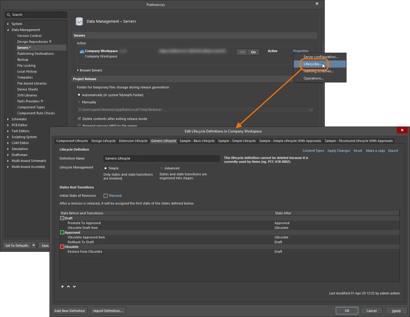
Lifecycle Definitions for the active connected Workspace are created and edited – in Altium Designer – through the Edit Lifecycle Definitions dialog.
Browser-based Lifecycle Management
Your connected Workspace provides the ability to define and manage lifecycle definitions through its browser interface, complementing the ability to do this through Altium Designer. And providing better visibility of the states and transitions involved, each lifecycle is built in a graphical way, showing at-a-glance the flows involved.
Defining and managing a lifecycle definition through the Workspace's browser interface is very much a visual affair. A definition is built rather like a flow diagram, using various graphical objects representing the states and state transitions (and stages if using an Advanced style of management).
For more information, see Lifecycle Management (Altium 365 Workspace, Enterprise Server Workspace).
Adding a New Definition
To create a new Lifecycle Definition, click the  button at the bottom of the Edit Lifecycle Definitions dialog. A new tab will appear in the dialog, ready to be configured.
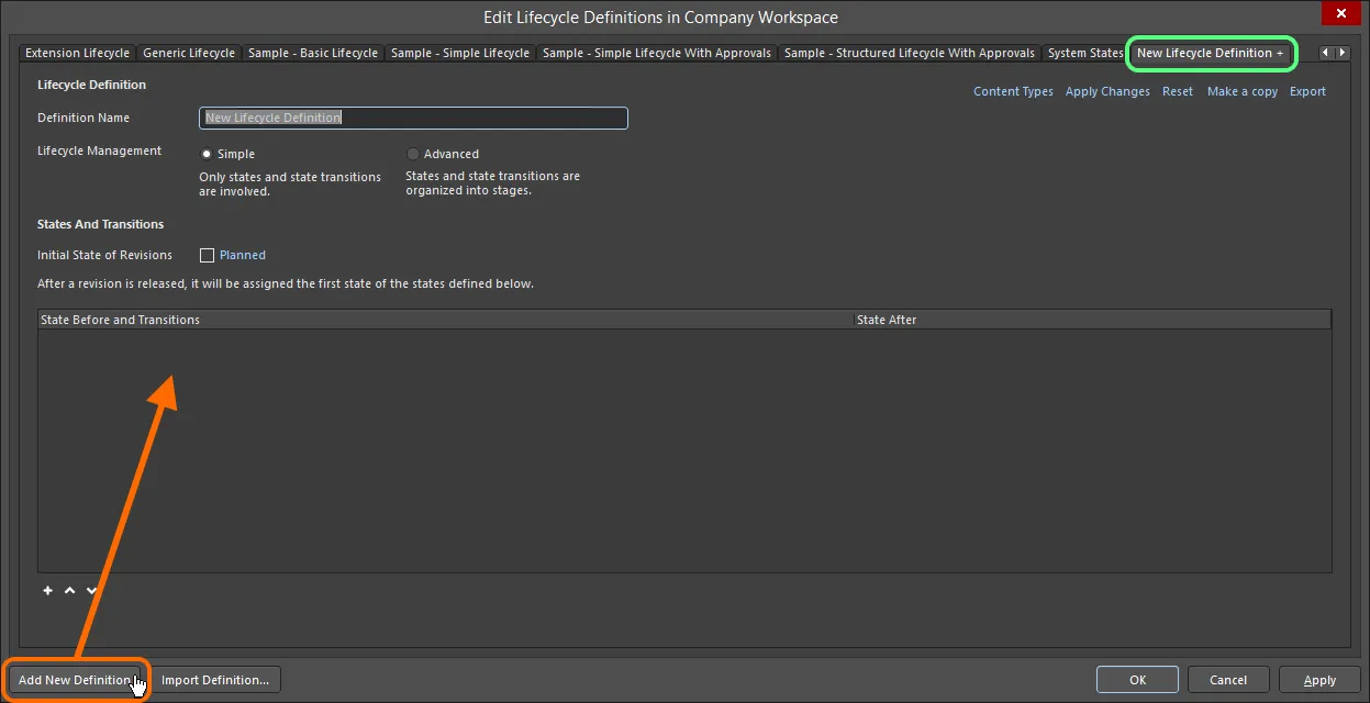
Create your own custom lifecycle definition.
A newly-added lifecycle definition is distinguished by a '+' suffix in its tab. This reflects that the definition is still being configured and has not yet been 'saved' to the set of lifecycle definitions available to the Workspace.
Configuring a Definition
Use the controls available within a lifecycle definition's tab to configure that definition as required.
Once a defined lifecycle definition is in use by an Item in the Workspace, that definition can not be deleted. You can however modify the definition to some extent, including renaming it, modifying its state attributes (color, transitions, applicability, visibility), adding new states to the definition, removing any unused states, and linking stages to revision levels (where applicable).
First, enter a meaningful name for the definition in the Definition Name field. The tab will dynamically reflect the name entered.
Use the Lifecycle Management controls to select the style of lifecycle management – either Simple or Advanced. The simple style means there are only States and State Transitions involved. The advanced style allows definition of Stages, into which the states are clustered.

Specify the name and style for the lifecycle definition.
Initial State
Use the Initial State of Revisions field to determine the starting state for an Item Revision, that is, the state for the revision in which it contains no released data – the 'pre-release state' as it were. By default, this state is named Planned. To change it, click the link and use the State Properties dialog to determine its name and a description, as well as text and background colors.
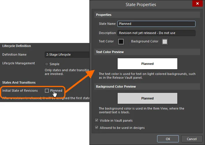
Configure the initial state for revisions.
Stages
If the Advanced style of lifecycle management is chosen, controls for adding and defining the required stages become available. A single stage – named Design - is provided by default, with the possibility to add a further two stages. To add an additional stage, click the Add Stage link.
Enter names for the stages as required by typing directly into the respective Stage Name field.

Add stages as required, which will be used to cluster states and create a more enriched, structured lifecycle definition.
To remove a stage, click the

control, to the right of the respective
Stage Name field.
States
The next step is to add the required states for the lifecycle definition. For a lifecycle definition based on the simple style of management, this will be a flat listing. For the advanced style of management, this will require adding states to the various defined stages.
Click the  control below a state listing to add a new state. Use the State Properties dialog that appears to define that state in terms of its name, description, and color attributes.
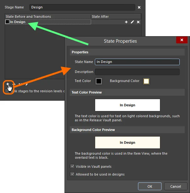
Adding a state to the lifecycle definition.
Options and Controls of the State Properties Dialog
Properties
-
State Name - specify a name for the State.
-
Description - enter a description for the State.
-
Text Color - click the color box to open the Choose Color dialog then select the desired text color.
-
Background Color - click the color box to open Choose Color dialog then select the desired background color.
Text Color Preview
Displays a preview of the text color.
Background Color Preview
Displays a preview of the background color.
-
Visible in Vault panels - with this option enabled, a revision of an Item using the parent lifecycle definition will be displayed in the Explorer panel when it is set to be in this lifecycle state. When this option is disabled, the revision will be hidden in both places. A hidden revision can, however, be displayed (overriding this option) by enabling the Show Hidden Revisions control in the Explorer panel.
-
Allowed to be used in designs - with this option enabled, an Item Revision in this state is permitted to be used in a design. It is deemed to be Applicable. If this option is disabled, an Item Revision in this state cannot be validly used and is deemed Inapplicable (or Not-applicable). It will be flagged as such in the Properties panel in Component mode and the Item Manager dialog. The project compiler can also be configured to find such occurrences.
Note that components whose Revision state is set to Inapplicable (Not-applicable) are not displayed in the Components panel.
A new state is added to the bottom of the list. Click on a state to select it, then use the  and
and  controls (below the state listing) to move it to the required location in the list.
When defining states for an advanced-style lifecycle definition, additional controls are available (below the state listing) to move a state between stages. Depending on the position of the stage, push the state to the stage on the right ( ), or left (
 ) as required.
To edit the properties of a state, click to select it, then click on the

control, to the far right. To delete a selected state, use the

control.

Example states defined across a two-stage lifecycle definition.
Transitions
The last step is to define the State Transitions – the paths between the different states. Click to select a state, then click the  control to the far right to add a new state transition. Use the State Transition Properties dialog that appears to define the transition in terms of its name, target (next) state, menu text, and permissions.
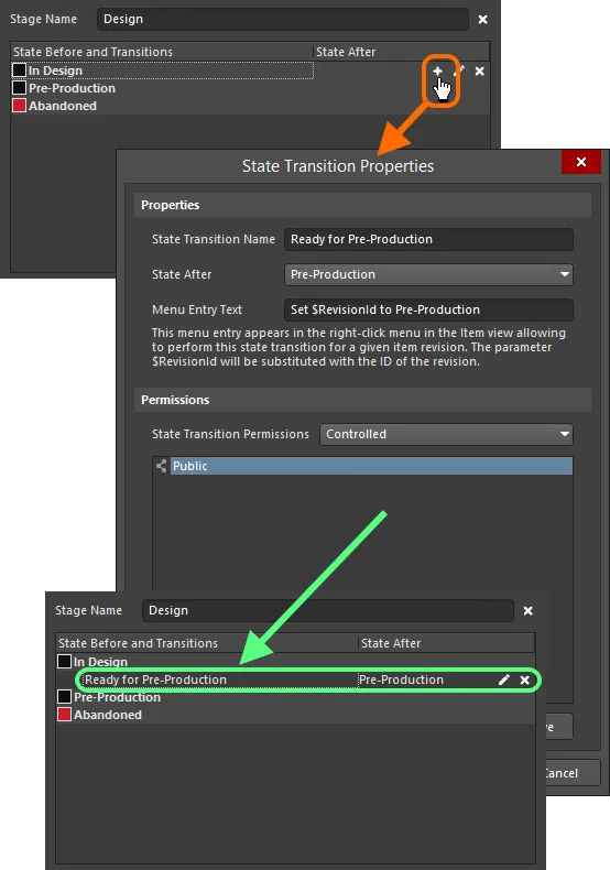
Adding a state transition.
Options and Controls of the State Transition Properties Dialog
Properties
-
State Transition Name - enter the name for the State Transition.
-
State After - use the drop-down to select the state that follows the State Transition that is being added.
-
Menu Entry Text - this is the text that will appear in the right-click menu in the Item view allowing to perform this state transition for a given item revision. The parameter $RevisionId will be substituted with the ID of the revision.
State Transition Permissions
Use the drop-down to select how the permissions for the State Transition are set:
-
Controlled - select this option to limit permissions based on the default Server permissions.
-
Using Approvals - choose this option to allow permissions that are selected for this specific State Transition, which can be added in the table below using the Add button.
Additional Controls
-
Add - use the drop-down to select from the following options:
-
Add Approval Group - select to add an approval group. The new group is named New Approval Group by default. You can edit the name using the Edit Approval Group Name command defined below.
-
Add Role - select to add a group using the Search for Role dialog.
-
Add User - select to add a User using the Search for Users dialog.
-
Edit Approval Group Name - select to open a dialog in which you can enter a name for a newly added approval group.
-
Move Up - click to move the currently selected item up one position.
-
Move Down - click to move the currently selected item down one position.
-
Remove - click to remove the currently selected group or user.
The Add commands are available only if Using Approvals is selected in State Transitions Permissions.
-
Remove - click to remove the currently selected group or user.
The
Menu Entry Text must be defined. This text will appear in the
Item view (or
Lifecycle aspect view tab in the
Explorer panel) when right-clicking on an Item Revision to transition it to a new state.
When entering menu text, use the entry $RevisionId as a placeholder for the Revision ID. For example, considering revision 01.A.1 of a particular Workspace Item, entering the menu text Promote $RevisionId to In Production will result in the menu displaying the entry Promote 01.A.1 to In Production.
A new transition is added to the bottom of the list. Click on a transition to select it, then use the  and
and  controls beneath the state listing to move it to the required location in the list.
Where the next state for a transition resides in a different stage, an indication arrow – in the color of the target state – will be displayed to show this.

Example of fully defined states and state transitions across a two-stage lifecycle definition. Arrows are used to indicate transitions across stages.
To edit the properties of a transition, click to select it, then click on the

control, to the far right. To delete a selected transition, use the

control.
To completely remove all defined states and transitions for a simple lifecycle definition, or all states and transitions for a specific stage in an advanced lifecycle definition, use the Clear command, available from the applicable right-click context menu.
Example Default Lifecycle States and Transitions
The following table provides a listing of states and state transitions used in the default Sample - Structured Lifecycle With Approvals lifecycle definition.
Current State
|
Possible Transitions
|
Next State
|
Comment
|
Planned
|
Perform Release
|
New From Design
|
All new, unreleased Item Revisions start in the Planned state. An Item Revision in this state cannot have its lifecycle status manually changed, it can only be released, automatically transitioning to New from Design.
|
New from Design
|
Set Ready for Prototype
|
Pending Prototype Approval
|
Indicates that this Item Revision has been released so is now New from Design. Once ready to go for prototyping, it can be transitioned to Pending Prototype Approval.
|
|
Abandon Design
|
Abandoned
|
If the Item Revision is deemed not necessary at this stage, it can be Abandoned.
|
Pending Prototype Approval
|
Approve for Prototype
|
In Prototype
|
Item Revision is ready to be approved for prototyping. Successful approval transitions the revision to the In Prototype state.
|
|
Disapprove for Prototype
|
New From Design
|
If an Item Revision fails to be approved for prototyping, it is transitioned back to New from Design.
|
Abandoned
|
Recover Design
|
New from Design
|
An abandoned Item Revision can be recovered, restoring it to New from Design.
|
In Prototype
|
Set Ready for Production
|
Pending Production Approval
|
The Item Revision is In Prototype, typically this is a state when you are ready to assemble the first physical prototypes. If it passes prototype testing then it can be transitioned to Pending Production Approval.
|
|
Rollback to Design
|
New from Design
|
If the Item Revision fails testing, then it should be transitioned back to New from Design.
|
|
Closed Prototype
|
Closed Prototype
|
If the Item Revision cannot be developed any further (perhaps it needs design changes, requiring a new Revision), then transition it to Closed Prototype.
|
Pending Production Approval
|
Approve for Production
|
In Production
|
Item Revision is ready to be approved for production. Successful approval transitions the revision to the In Production state.
|
|
Disapprove for Production
|
In Prototype
|
If the Item Revision cannot be released to production, it can be transitioned back to In Prototype.
|
Closed Prototype
|
Recover Prototype
|
In Prototype
|
A Closed Prototype is one that is considered unable to be further developed. If it is possible to continue with it, it can be transitioned back to In Prototype.
|
In Production
|
Rollback to Prototype
|
In Prototype
|
If an Item Revision is in Production but there is some reason it cannot be produced, it can be transitioned back to In Prototype.
|
|
Deprecate
|
Deprecated
|
If you are planning to stop making the Item at its current revision (perhaps a component used on the board is becoming difficult to buy), you transition it to be Deprecated.
|
|
Obsolete Production Item
|
Obsolete
|
If an Item Revision that is currently In Production is no longer able to be made, it can be immediately Obsoleted.
|
Deprecated
|
Obsolete Deprecated Item
|
Obsolete
|
Deprecated typically means production can continue from existing stock, but new components for that Item Revision should not be ordered. If this changes and such stock is no longer available, the revision can be made Obsolete.
|
|
Reactivate Deprecated Item
|
In Production
|
Restore a Deprecated Item to be In Production.
|
Obsolete
|
Reactivate Obsolete Item
|
In Production
|
Restore an Obsolete Item to be In Production.
|
|
Deprecate Obsolete Item
|
Deprecated
|
Restore an Obsolete Item to Deprecated.
|
Controlling Transitions between Lifecycle States
The connected Workspace provides great flexibility for deciding who can make particular state transitions for an Item Revision in that Workspace – the action of transitioning a revision from one state to another different state, as defined by the lifecycle definition employed for its parent Item. It is possible to prohibit standard (non-administrative) users from transitioning between specific lifecycle states on the fly while opening up permissions to more than just Workspace Administrators. You have the ability to specify permissions at the global level – as part of global operation permissions for the Workspace – and also at the individual state transition level. The latter act in conjunction with those settings at the global level, and facilitate fine-tuning of permissions for those more important transitions (for example setting an Item Revision to be Ready for Production).
Alternatively, standard users can be made to request approval for specific state transitions. In turn, these Approval Requests are sent to, viewed, and acted upon, by those designated to be members of one or more Approval Groups.
With various levels of permission control, you can define a lifecycle state transition strategy that adheres to your organization's preferred approach.
Permissions can be defined at two levels:
-
Globally – defining which users and/or groups can perform state transitions, for the entire range of defined transitions across all defined lifecycle definitions.
-
Locally – specifying permissions at the individual state transition level.
Global State Transition Permissions
Global state transition permissions are defined and managed from within Altium Designer using the Edit Operation Permissions dialog. Access to this dialog is made from the Data Management – Servers page of the Preferences dialog. For the connected Workspace whose permissions you wish to browse/modify, click the Properties control at the right-hand side, and choose the Operations command from the associated menu.
The Workspace operation entry of significance here is Move revision between lifecycle states.
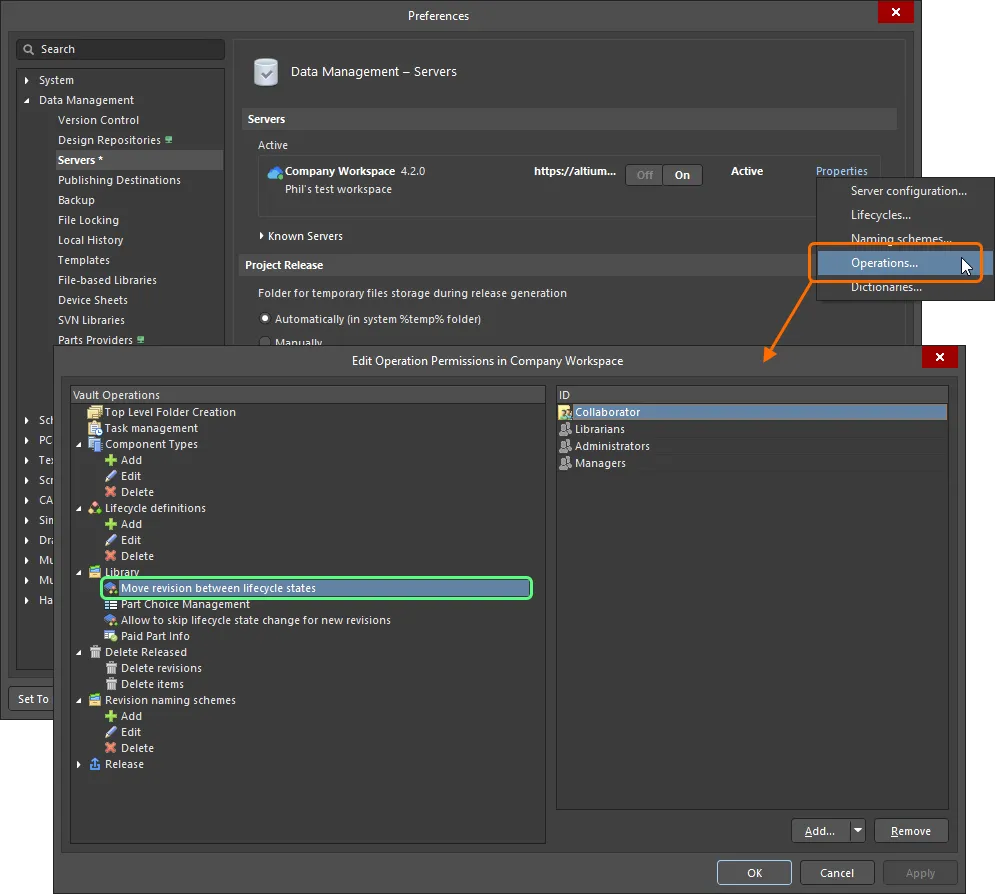
Access and configure, at the global level, who is permitted to perform lifecycle state transitions.
For a new connected Workspace, the default permission settings for this operation are:
-
Administrators
-
Collaborator
-
Librarians
-
Managers
For most cases, these default permission settings will be fine and would need to be modified only in exceptional circumstances.
Define additional permissions as required (click the Add button). State transition permissions at this global level can be assigned to the following entities:
-
 Administrators (itself a defined group).
-
 Collaborator (this is a user who has edit rights for an Item/Revision).
-
 Owner (for released data, this is the person who created the initial Item).
-
 Specific user-defined group.
-
 Specific User.
Management of users, as well as defined groups, is performed using the Workspace's browser-based interface. This can be done from an external browser. For detailed information, read about Managing Your Workspace Membership (Altium 365 Workspace, Enterprise Server Workspace).
Local State Transition Permissions
Permissions for a particular state transition are defined in the associated State Transition Properties dialog, accessed from the applicable States and Transitions region of the lifecycle definition currently being configured in the Edit Lifecycle Definitions dialog.
To edit the properties of a transition, click to select it, then click on the  control at the far right.

Access controls for defining permissions for the state transition being edited.
Choose the type of permission control that you wish to employ for the transition using the State Transition Permissions field. Two options are provided:
-
Controlled – this type allows you to refine exactly who can perform this transition, through specification of one or more users and/or groups. This type of local permission control is used in combination with permissions set at the global level (see How Permissions are Applied). Use the controls in the region below to define permitted entities accordingly. By default, the Anyone entity is added, meaning that all users at this local level are permitted to perform the transition.
To set up specific users and/or groups, first select and then remove the Anyone entity. You can then add a user or group as required from the menu associated with the Add button. Use the subsequent Search for Users, or Search for Role, to find the required user or group respectively.
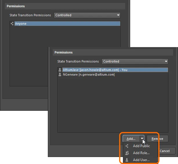
With Controlled permissions, you can switch from access by anyone to only those users/groups specified.
-
Using Approvals – this type allows any standard user to request that this state transition be performed. Requests are handled by one or more users added (individually or through groups) to defined Approval Groups. Any member of such a group can authorize, or reject a transition request. In addition, multiple approval groups can also be defined and ordered. This allows for multiple levels of approval.
Use the controls in the region below to define the approval group(s) accordingly. By default, a single, empty approval group is added ready – New Approval Group. This can be renamed as required using the Edit Approval Group Name command from the menu associated with the Add button (or the region's right-click menu).
You can add a user or group to a selected approval group as required, from the menu associated with the Add button (or the region's right-click menu). Use the subsequent Search For Users dialog, or Search For Role dialog, to find the required user or group respectively. Order multiple approval groups using the Move Up and Move Down commands from a menu – approval is from the top, down.
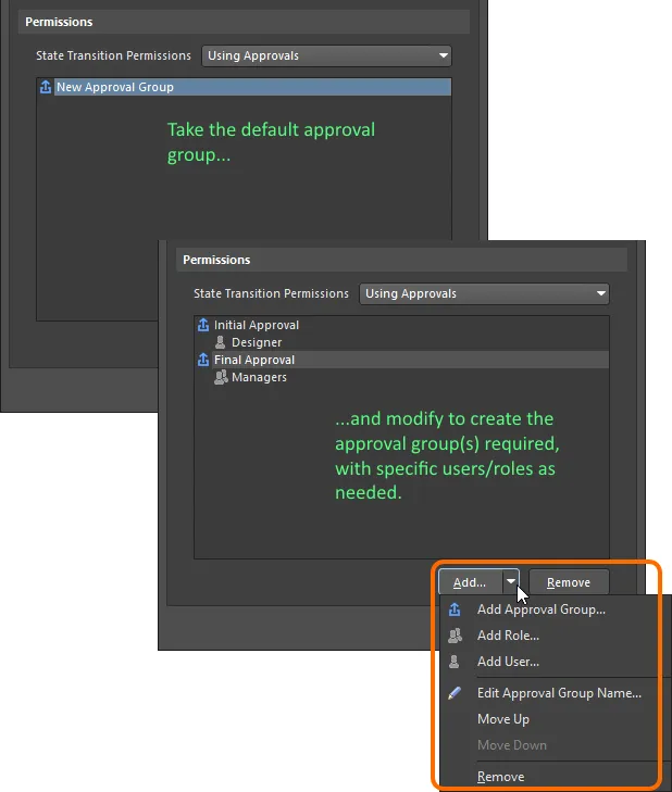
With Using Approvals, all non-admin users must request transition, which is acted on by a user in one or more defined approval groups.
Management of users, as well as defined groups, is performed using the Workspace's browser interface. This can be done from an external browser. For detailed information, read about Managing Your Workspace Membership (
Altium 365 Workspace,
Enterprise Server Workspace).
How Permissions are Applied
How permissions are applied, depends on the type of permission control chosen and configured at the state transition level:
-
Controlled Permissions – for a user to be able to perform the state transition, the following conditions must be met:
-
They must have permission at the global level to
Move revision between lifecycle states (defined in the Edit Operation Permissions dialog).
-
They must have permission at the local level for this particular state transition.
-
They must also be a collaborator for the Item Revision whose lifecycle state is being transitioned (i.e. they must have editing rights).
These three conditions are ANDed – if one is not met, then the user will be prevented from performing that specific transition.
For non-administrative users, the default permission settings (Collaborator at the global level, and Anyone at the local state transition level) mean that you just need to make a user a collaborator for the required Item Revision, to meet all conditions. Then for key transitions, you can simply tighten permissions at the local state transition level, so that not just any collaborator can perform the transition.
-
Using Approvals – all non-administrative users must use the approvals system and send a request to perform the state transition. The approvals system doesn't require the user to have permission to make state transitions at the global level, nor does a user require to be a collaborator for the Item Revision.
While a user does not need to be a collaborator for the Item Revision, it must be shared with them, otherwise, they will not be able to see it in the Workspace.
Workspace Administrators will always be able to transition Item Revisions between different states, irrespective of locally defined state transition permissions.
Linking Stages to Levels of the Revision Naming Scheme
Revisions and lifecycle states can be incremented from the applicable right-click menu in the Item view, or the Lifecycle aspect view tab in the Explorer panel. While establishing a new revision and promoting the lifecycle are completely separate tasks that are done for different reasons (a new revision when there is a design change, a new lifecycle state to reflect the enhanced usability of that Item Revision), they are inter-related.
For a lifecycle definition based on the advanced style of management, the defined stages can be linked to the revision levels of the employed revision naming scheme. Do this using the option at the bottom of the Edit Lifecycle Definitions dialog.

Option to link stages to revision levels.
This creates a relationship between the lifecycle stage and the revision level. What that means is when an Item Revision's lifecycle is incremented so that it moves from a state in one stage to a state in another stage, then the available revision modification type commands – on the right-click menu – will change too.
Consider the default lifecycle definition Sample - Structured Lifecycle With Approvals, and a 3-level revision naming scheme (with levels for Revision, Prototype, and Model). If an Item Revision is in the state New From Design, in the first stage, then the revision-type options on the right-click menu include: establish a new Revision; a new Prototype; or a new Model.
If the lifecycle is then incremented to the point where it is now In Prototype, it will have moved to the second stage. Right-clicking on it, the available revision-type options now include: establish a new Prototype; or a new Model, that is, there is no option to start a new Revision. This behavior is intuitively expected – if the design has progressed to Prototype, then if a design change was needed, a new Prototype would be needed, or even a new Model, depending on the scope of that change.
Once the Item Revision reaches the In Production state, in the third stage, the revision-type option to establish a new model is available only, again as expected.
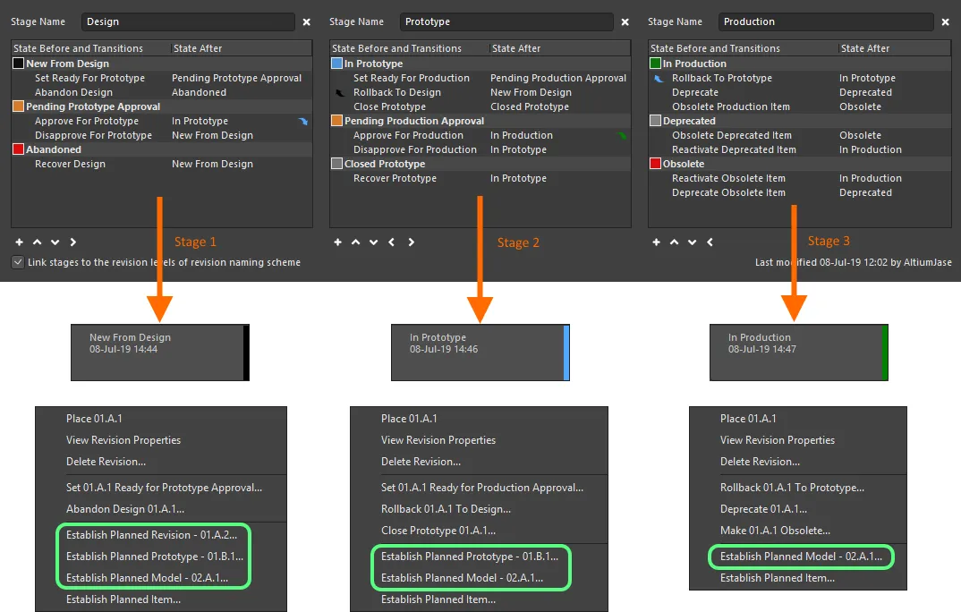
When linked, revision-type commands change as the Item Revision's lifecycle state progresses through the different stages defined.
Saving a Definition
Whether a new lifecycle definition has been added, or an existing lifecycle definition has been modified in some way, that lifecycle definition must be saved. Although there is no actual 'save' control, there are controls available to perform this:
-
For a new lifecycle definition – distinguished by a '+' suffix – either use the Add Definition control (at the top-right of the definition's tab) or click the dialog's main
 button.
-
For an existing lifecycle definition that has been modified – distinguished by a '*' suffix – either use the Apply Changes control (at the top-right of the definition's tab) or click the dialog's main
 button.
In either case, the suffix will be removed and the new (or modified) definition will be available as part of the set of lifecycle definitions available to the Workspace.
Using the dialog's main

button provides batch-style 'saving' while keeping the dialog open.
Ensure that a lifecycle definition has truly been added, or changes have been applied, prior to clicking the OK button. Doing so without 'saving' the definition will result in closing the dialog and the changes being lost. In addition, where more than just the first state has been defined for a lifecycle definition, transitions to effectively connect those states must be defined, or the changes cannot be applied. An error dialog will flag this situation, listing the 'unreachable' states.
On re-opening the Edit Lifecycle Definitions dialog, the collection of definitions will appear sorted by name, in ascending alphabetical order from left to right.
In the spirit of facilitating a clear and transparent audit trail – of whom changed what, and when – details of when a lifecycle definition was last modified are provided at the bottom-right of its tab.
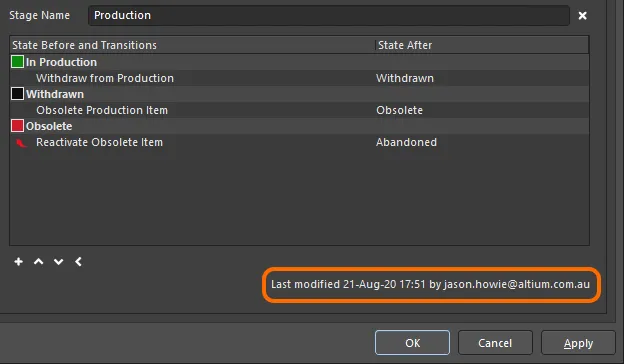
Identifying when a lifecycle definition was last modified, and by whom.
At any point prior to applying changes for the active definition, those changes can be 'rewound' in full by clicking the Reset control, at the top-right of that definition's tab.
Renaming a Definition
This feature is only available for a user with administrative privileges for the Workspace.
To rename an existing, used lifecycle definition:
-
Access the Edit Lifecycle Definitions dialog for the active connected Workspace.
-
Click the tab for the definition whose name you need to change.
-
Modify the name in the Definition Name field.
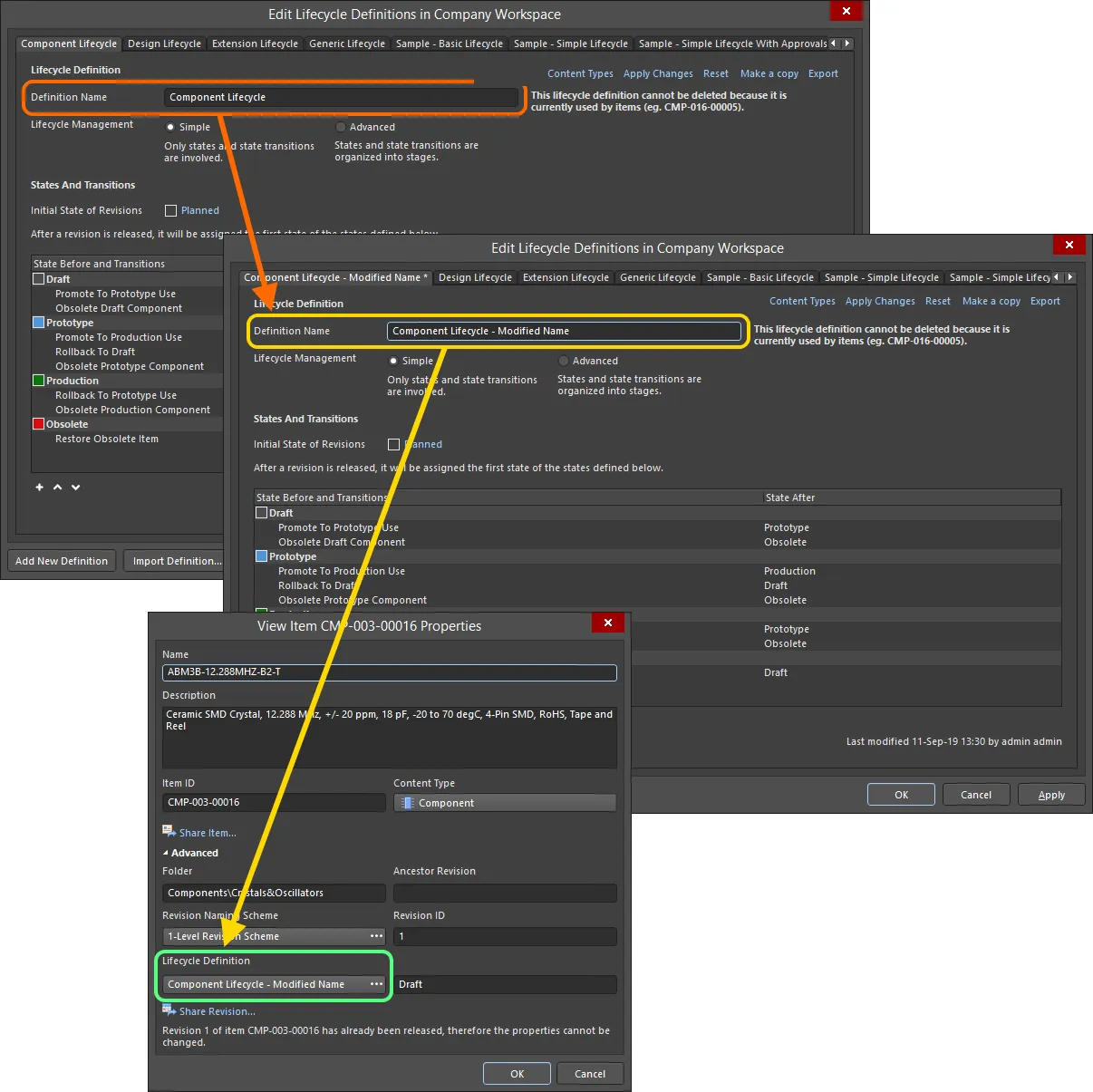
Example of renaming a lifecycle definition and verifying the change in the properties of an Item already using that definition.
Copying a Definition
New lifecycle definitions do not need to be created from scratch. The Edit Lifecycle Definitions dialog provides the ability to quickly copy any of the existing definitions. To do so:
-
Make the required lifecycle definition that is to be copied the active definition.
-
Click the Make a copy control at the top-right of that definition's tab.
-
An exact copy of the definition will be taken, creating a new definition with the initial default name of
New Lifecycle Definition. Rename as required.
-
Click the Add Definition control (or the main
 button) to effectively save the new definition.
Deleting a Definition
To delete an existing lifecycle definition, select it – making it the active definition in the Edit Lifecycle Definitions dialog – then click the Delete control at the top-right of the definition's tab.
A lifecycle definition that is currently being used by an Item in the Workspace cannot be deleted.
Permanent deletion of a lifecycle definition is effected upon clicking the dialog's main  button (or clicking OK). Prior to this, the delete operation can be undone by clicking the
  button at the bottom of the dialog.

The operation to delete lifecycle definitions can be undone.
Exporting and Importing Definitions
User-defined lifecycle definitions are available for use only in the connected Workspace in which they are defined. The Edit Lifecycle Definitions dialog features Export and Import capabilities, allowing definitions to be ported between Workspaces.
The lifecycle definition is stored in a Lifecycle Definition file (*.definition).
To export a lifecycle definition, click on the Export control at the top-right of its tab. Use the subsequent Save Lifecycle Definition dialog to determine where and under what name the file is to be saved.
To import a lifecycle definition, click on the  button at the bottom of the Edit Lifecycle Definitions dialog. Use the Open Lifecycle Definition dialog to browse to and open the required Lifecycle Definition file. The lifecycle definition will be added to the list of existing lifecycle definitions available to the Workspace.
An imported lifecycle definition appears as a new definition, complete with '+' suffix. It's name is that defined within the Definition file and not the name of the file itself. Ensure that it is 'saved' by clicking the
Add Definition control or the dialog's main

button.
Some predefined example lifecycle definition files are available in the \Program Files\Altium\AD<Solution/Version>\System\EDMSTemplates folder for a default Altium Designer installation.
Controlling the Use of a Lifecycle Definition
Control over which Item types can use a particular lifecycle definition can be defined and enabled at a global level when defining each definition. If this feature is enabled, then only those allowed definitions will be available when choosing the lifecycle definition for a particular Item type. This gives you that extra level of control to ensure created Items of a particular type only use the lifecycle definition you require.
Control is performed from within the Content Types dialog. Click on the tab for the particular definition whose access you wish to configure, then click the Content Types link, at the top-right of the definition's tab.

Accessing the Content Types dialog – command central for determining which content types can use the lifecycle definition being configured.
The Content Types dialog lists all of the supported content types that can be created in your active connected Workspace (by the user, or by the system). The option above the list – Control Lifecycle Definition per Content Type – provides global control over whether the feature is active (enabled) or not (disabled), for that particular definition. Enable this option, then enable the associated Use option for each content type that you would like to be able to use that definition.
To be able to create a Workspace project, the Use option must enabled for the Project content type in at least one lifecycle definition.
-
Refer to the Working with Items page to learn more about supported content types. Other content types listed in the Content Types dialog but not described there, are not functional within the software.
-
An incarnation of this same dialog is used to control the use of a particular revision naming scheme. See Controlling the Use of a Revision Naming Scheme for more information.
Switching between Advanced and Simple Lifecycle Management Modes
You can switch an existing lifecycle definition from using the Advanced style of lifecycle management (states, state transitions, and stages) to using the Simple style of management (states and state transitions only). When you enable the Simple option, the Confirm Merge States dialog will appear. Use this dialog to determine how to handle the switch as follows:
-
Click Yes – all defined states (and state transitions) across Stages 1, 2, and 3, are merged into a single flat listing of states.
-
Click No – all defined states (and state transitions) in Stages 2 and 3 are deleted. Only those states (and state transitions) in Stage 1 (the left-most stage) will remain in a single flat listing of states.
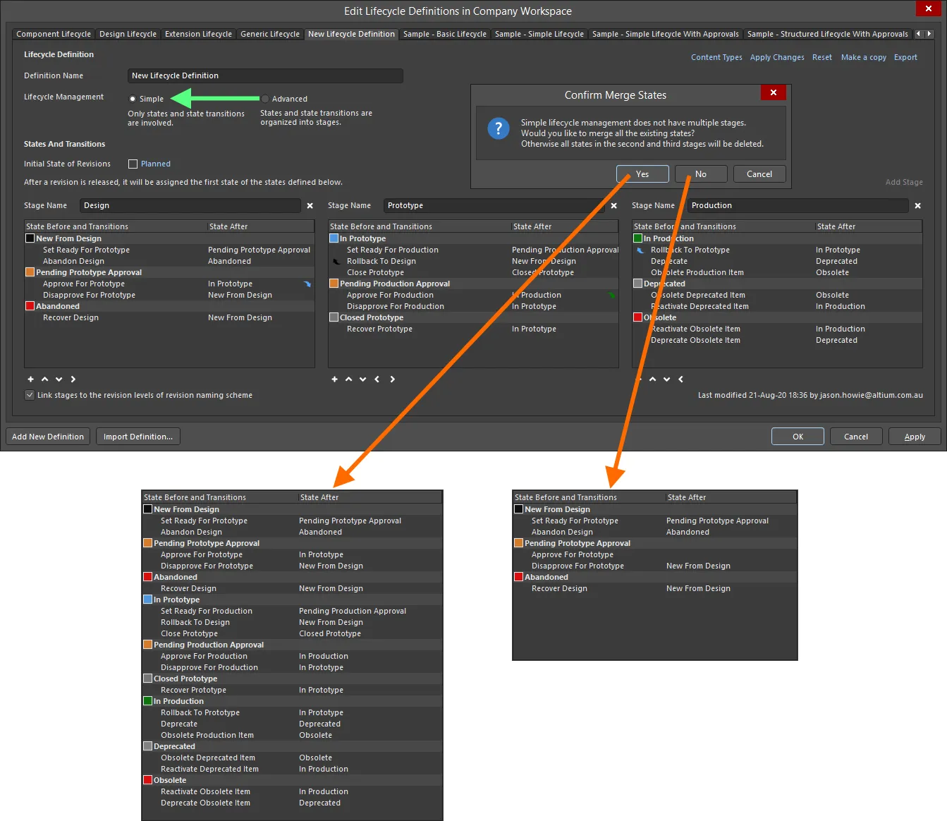
Switch style of lifecycle management – from Advanced to Simple – with control over how the states (and state transitions) in other stages are handled.
State Transition Approval Requests
The following sections take a closer look at the various aspects of using the approval system to allow non-administrative users of your Workspace, to perform specific state transitions.
Creating a Request (Requesting Approval)
Requesting approval for a state transition is performed within Altium Designer from the Lifecycle aspect view for the required Item Revision (in the Explorer panel), or from the graphical lifecycle region in the detailed Item view. Right-click on the lifecycle for the revision and choose the command that requests the transition. A Confirm dialog appears, in which you can enter a note as to why you are making the request – which can aid the approval group members in their deliberations over whether or not to ultimately approve your request! Click Yes to effect creation of the request.
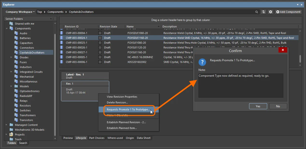
Request the state transition, and add a helpful note to substantiate your case.
Upon creation, members of the applicable approval group for that state transition will receive an email notification – provided the Email Notifications feature has been enabled.
Configuration of the Email Notifications feature is performed by a Workspace administrator on the Email Notifications page of the Workspace's browser interface (Admin – Settings – Email Notifications).
Viewing Approval Requests
For both the originator of a state transition request (Requester) and the user(s) defined in the applicable approval group for that state transition (Approvers), pending requests are presented through the Explorer panel using a dedicated Approval Requests folder.
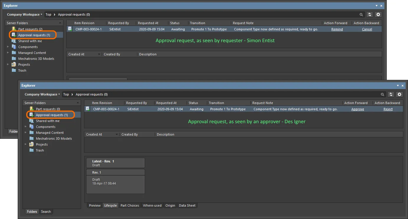
An example Approval Request in the Approval Requests folder, as seen by the requester (Simon Entist) and one of the members of the defined (initial) approval group for the particular state transition (Des Igner).
The number next to the
Approval Requests folder name indicates how many pending requests there are. If the option to
Show Approved Requests is enabled (from the

menu), then this number will reflect the total (pending + approved).
The following information is presented for each approval request:
-
Item Revision – the specific Item revision for which the request is being made.
-
Requested By – the originator of the request (the requester). The entry here takes the user's User Name.
-
Requested At – the date and time at which the request was created.
-
Status – the current status of the request. This can be one of the following states:
-
Awaiting – the request is currently awaiting action by one or more approvers.
-
Approved – the request was approved. Note that this state will only be entered upon full, complete approval, by all approval groups defined for that transition.
-
Transition – the specific state transition that is being requested for this Item revision.
-
Request Note – any note that has been added by the requester, at the time the request was made.
-
Action Forward – the controls presented here are only for pending requests (those with a status of
Awaiting). Controls differ to cater for the two parties as follows:
-
Requester – the user who created the request can Remind it.
-
Approvers – a user within an approval group can Approve the request.
-
Action Backward – the controls presented here are only for pending requests (those with a status of
Awaiting). Controls differ to cater for the two parties as follows:
-
Requester – the user who created the request can Cancel it.
-
Approvers – a user within an approval group can Reject the request.
Action-based commands for the approval request are also available from the right-click menu for the Item Revision's lifecycle (within the Lifecycle aspect view).
Actioning a Request
As briefly described in the previous section, both the requester and approver have actions that they can take. The following collapsible sections take a closer look at each of those actions:
Remind
This action can be taken by the requester if they have been waiting for approval, but have not yet got it. It is analogous to nudging someone or bumping a forum post – in other words, a polite way of reminding those in the applicable approval group that they need to take action (either way). Click the Remind control associated with the approval request. A Confirm dialog appears, in which you can enter a note that perhaps raises the level of urgency for the approval to be made! Click Yes to effect the reminder – members of the applicable approval group for that state transition will receive an email notification – provided the Email Notifications feature has been enabled.
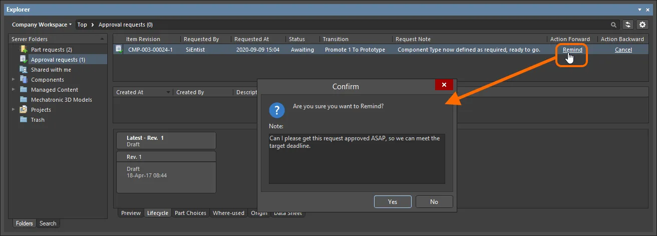
Example use of the Remind action.
Approve
This action can be taken by a member of the applicable approval group, to approve that request. Click the Approve control associated with the approval request. A Confirm dialog appears, in which you can enter a note if required. Click Yes to effect the approval – the requester for that state transition will receive an email notification – provided the Email Notifications feature has been enabled.
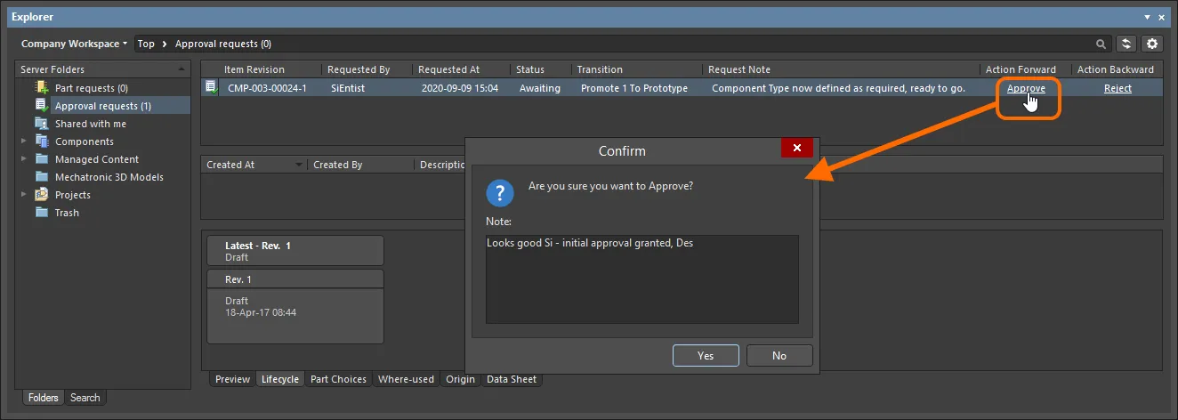
Example use of the Approve action.
If there is only one approval group, approval of the request will result in the state transition occurring automatically. If there are multiple approval groups, then the request will await approval from a member of the next group. If the approver in the first approval group is also a member of the next approval group, approval will be automatic for that second group.
Reject
This action can be taken by a member of an approval group, to reject that request. Click the Reject control associated with the approval request. A Confirm dialog appears, in which you can enter a note if required, perhaps indicative of why the request has been rejected. Click Yes to effect the rejection – the approval request will be deleted, and the requester for that state transition will receive an email notification – provided the Email Notifications feature has been enabled.
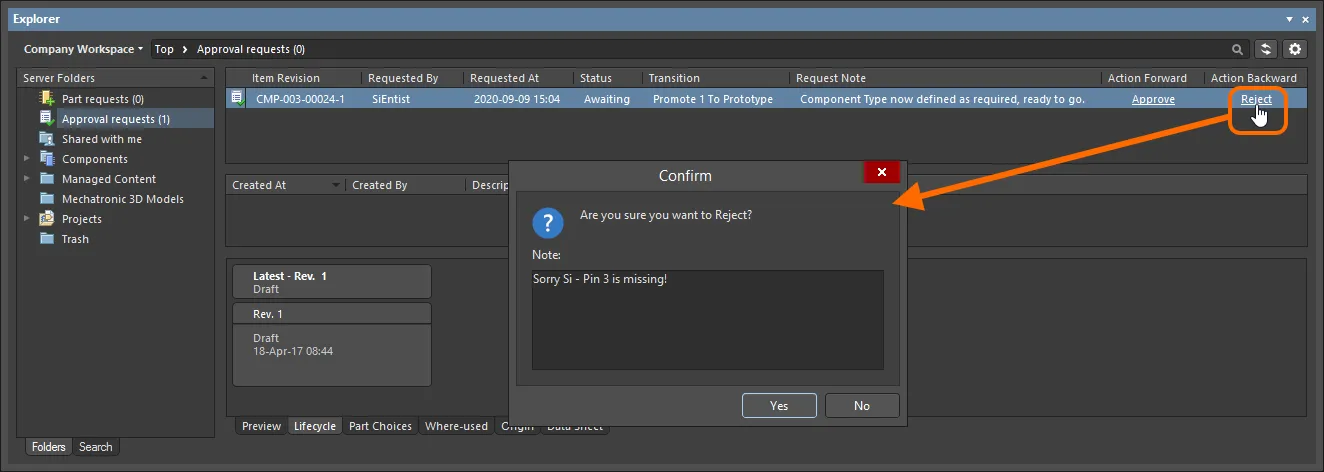
Example use of the Reject action.
Cancel
This action can be taken by the requester if they have been waiting for approval but have since decided to cancel the request. This could happen, for example, if another issue has since been found that would negate the need to transition to the required lifecycle state. Click the Cancel control associated with the approval request. A Confirm dialog appears, in which you can enter a note if required. Click Yes to effect the cancellation – the approval request will be deleted.
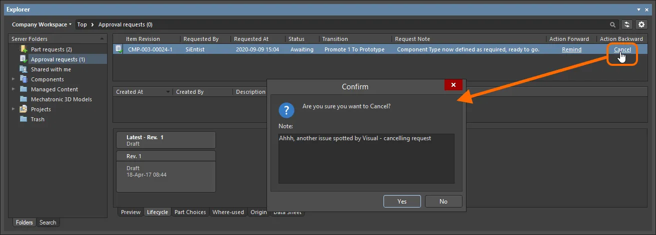
Example use of the Cancel action.
Approval Information Stream
When a request is approved, notification is also available in the central region of the page, when browsing that approval request. This information consists of the following elements:
-
Created At – the date and time at which the approval request was approved.
-
Created By – the member of the relevant approval group who approved the request. The entry here takes the user's User Name.
-
Description – an entry that consists of an auto-generated message, along with any note included by the approver, at the time approval was given. The auto-generated part of the description depends on the type of approval:
-
Final approval (from a member of the only, or last, approval group) –
task approved and completed.
-
Intermediate approval (from a member of an approval group that is not the last approval group) –
task approved and assigned to next approval group <ApprovalGroupName>.
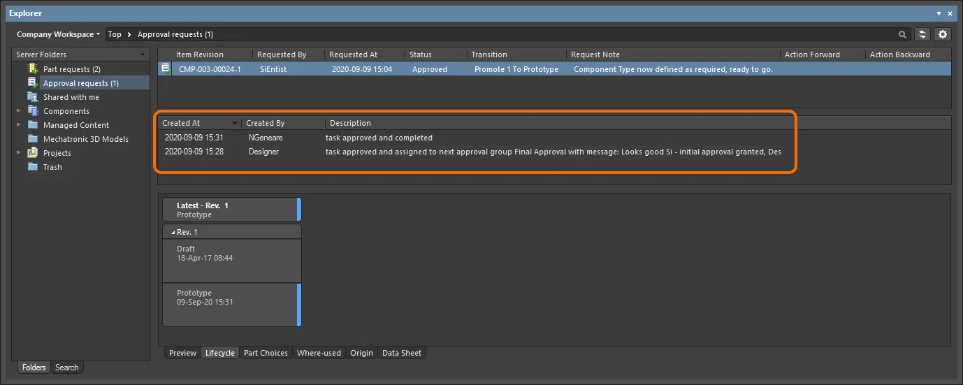
An example of the approval stream for a particular Item Revision, as seen by the requester. In this case, the transition had to pass through two stages of approval (obtaining approval from a member of two different approval groups).
Such approval information is available only for approval requests that have a status of Approved, or have a status of Awaiting, and have been approved by the first of multiple associated approval groups.
The following people see this information:
-
The requester of the state transition.
-
The user who gives final approval for the request. So where multiple approval groups are involved, only the member of the final approval group – who gives the final approval – will see this information. A member of an approval group that gives intermediate approval will not see this stream.
Controlling Item Revision Visibility and Applicability
When configuring each individual state for a lifecycle definition, you have the ability to define additional state attributes that control the visibility and applicability of an Item revision that uses that lifecycle definition and which enters that state. In terms of applicability, a project violation report can also be configured to detect and flag any Workspace items being used in a design whose revisions are in non-applicable states – catching and averting issues prior to release.
Controls for determining whether an Item Revision in a particular state is visible and/or applicable are available in the State Properties dialog. From within the Edit Lifecycle Definitions dialog access this dialog for the required state either by double-clicking on the state's entry within the parent lifecycle definition or by selecting its entry and clicking the edit icon that appears ( ).
).

Use attributes defined at the state level to control the visibility and/or applicability of an Item Revision entering that state.
The two options are:
-
Visible in Vault panels – with this option enabled, a revision of an Item using the parent lifecycle definition will be displayed in the Explorer panel when it is set to be in this lifecycle state. When this option is disabled, the revision will be hidden. A hidden revision can be displayed (overriding this option) within the Explorer panel by enabling the Show Hidden Revisions control (see Showing Hidden Revisions).
-
Allowed to be used in designs – with this option enabled, an Item Revision in this state is permitted to be used in a design. It is deemed to be Applicable. If this option is disabled, an Item Revision in this state cannot be validly used and is deemed Inapplicable (or non-applicable). It will be flagged as such in the Properties panel and the Item Manager dialog (see Flagging Inapplicable Revisions). The project compiler can also be configured to catch such occurrences (see Detecting Inapplicable Revision States on Compilation).
In the
Components panel, all latest revisions of components allowed to be used in designs are presented, even if those components have entered a state whose
Visible in Vault panels option has been disabled. The
LifeCycle filter can be used to search for components in a particular state (or states).
Showing Hidden Revisions
For an Item Revision entering a lifecycle state that has its Visible in Vault panels attribute disabled, that revision will, by default, not be displayed in the Explorer panel. And if it is the latest revision of the Item, then the entire entry for that Item will effectively be hidden from view. This visibility state – defined at the state level – can be overridden globally for all Items when browsing in the Explorer panel. To display all Item Revisions that are currently not visible, click the  control at the top-right of the Items region of the panel, then enable the Show Hidden Revisions option on the associated menu.
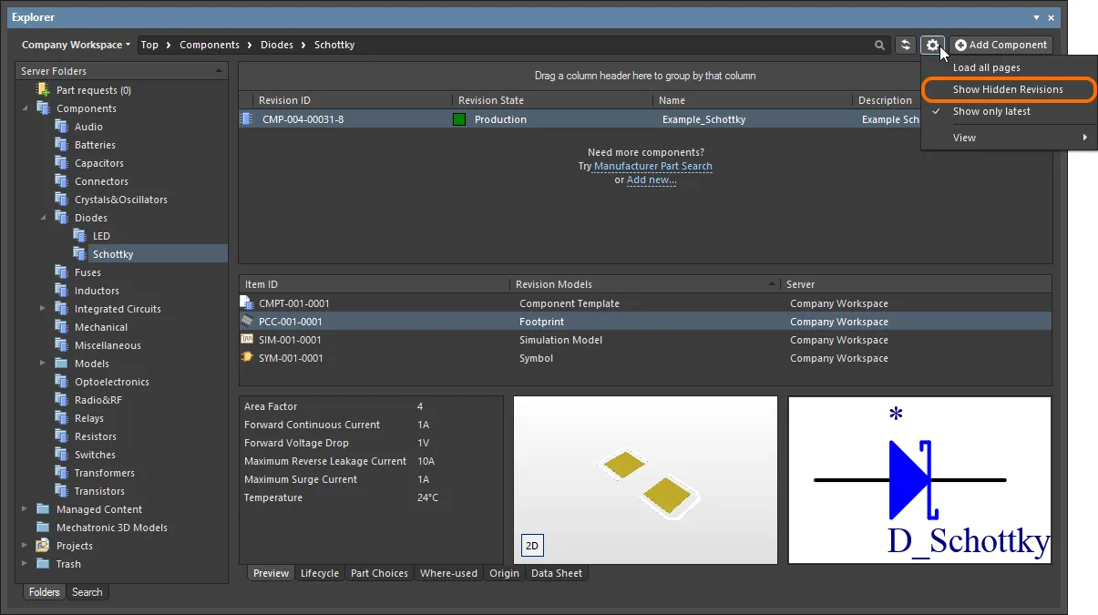
Displaying hidden Item Revisions while browsing content in the Explorer panel. Hover over the image to see the result.
Flagging Inapplicable Revisions
Typically, a lifecycle state that is set to be hidden (Visible in Vault panels option disabled) will also be made inapplicable (Allowed to be used in designs option also disabled). For example, a revision of a component that is currently Depracated or Obsolete should have no place on the latest design spin! Hiding revisions of Items that have entered such states is one thing – if you can't see a component, for example, you can't place it. But you may already be using instances of such Item Revisions in a design, or inadvertently placed an inapplicable revision of a component by virtue of having shown hidden revisions whilst browsing!
Not to worry. Aside from catching Component Item Revisions that are in inapplicable states upon compilation (see next section), you can manually interrogate the applicability of Item Revisions (components and managed sheets) directly in your design software. This is achieved through the Properties panel, when browsing the item's properties, or through use of the Item Manager.
-
Properties panel – when using this panel to browse the properties of a placed instance of a revision of a component or managed schematic sheet, indication is presented to the right of the revision status entry. If the revision is in an inapplicable state (not allowed for use in designs) the entry will display Not applicable. If the revision is in an applicable state (allowed for use in designs) the entry will either reflect that the revision is the latest (Up to date) or not (Out of date).
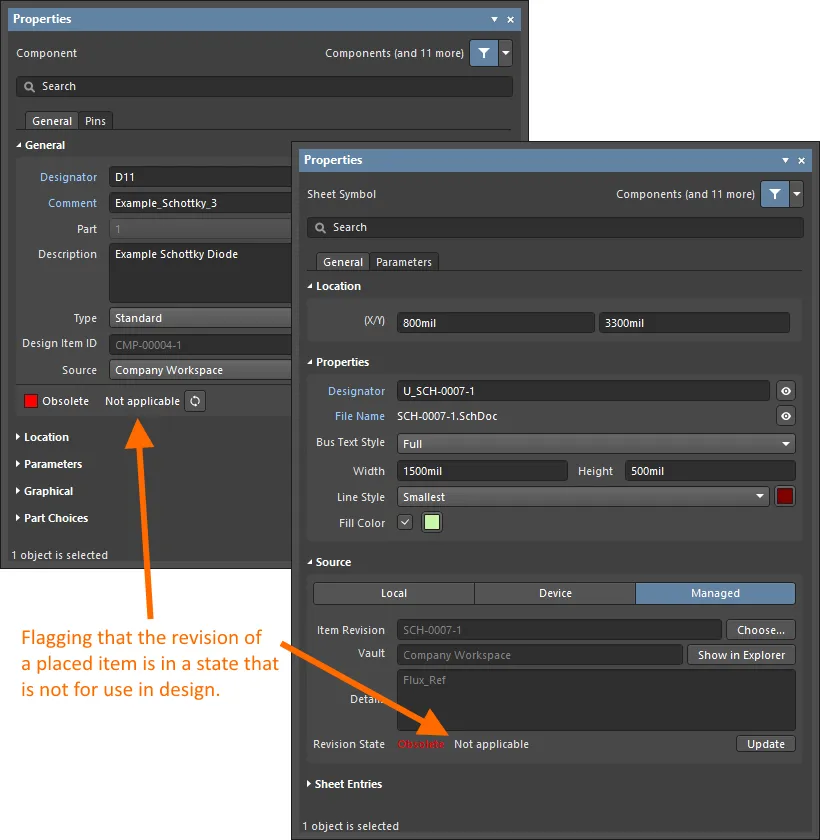
Reflecting inapplicability at the properties level for a placed instance of a revision of a component and managed schematic sheet.
-
Item Manager – in the Item Manager dialog (Tools » Item Manager), indication is presented in the Revision Status field. If the revision is in an inapplicable state (not allowed for use in designs) the entry will display Not applicable. If the revision is in an applicable state (allowed for use in designs) the entry will either reflect that the revision is the latest (Up to date) or not (Out of date).
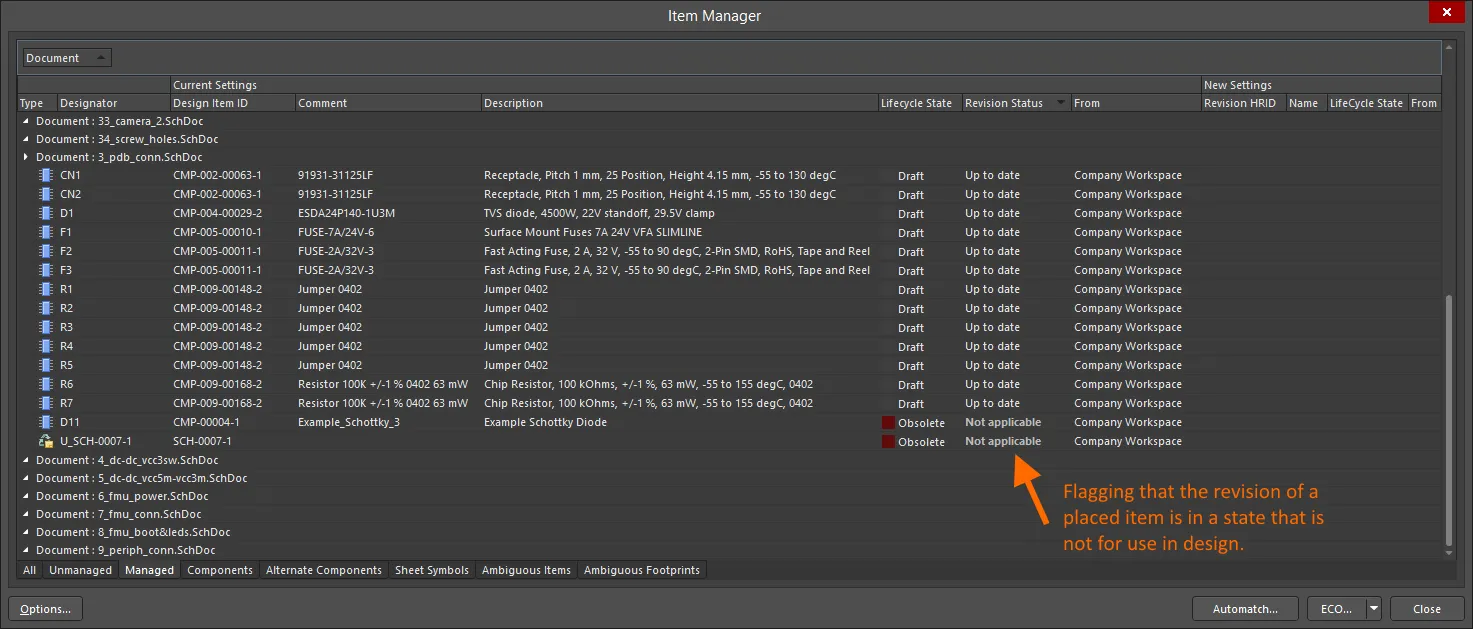
Reflecting inapplicability through the Item Manager dialog for a placed instance of a revision of a component and managed schematic sheet.
-
Use controls available in the Properties panel or Item Manager dialog to choose a later revision of the Item that is in an applicable state or, if this is not possible (the Item, in general, is not for design use), simply choose an applicable revision of a different Item.
-
When changing the lifecycle state of a component item revision (learn more), Altium Designer checks that its referenced child item revisions (template and referenced models) are in an applicable state to do so. Otherwise, the state transition status will indicate that a child item revision is in an inapplicable state.
Detecting Inapplicable Revision States on Project Validation
For placed instances of Component Item Revisions, the applicability of the states of those revisions can be checked as part of project validation. At the heart of this checking is the Component revision has inapplicable state violation type, part of the Violations Associated with Components category. Configure the reporting mode for this check on the Error Reporting tab of the Project Options dialog.
The default
Report Mode for this violation type is

. Modify to suit your design requirements.
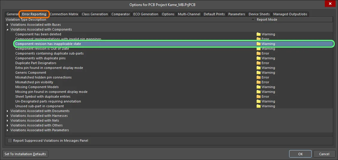
Project validation includes a check for violations concerning components in inapplicable revision states. A violation will occur if the lifecycle state of a placed Component Item Revision has been specified as not being allowed for design purposes.
If compiler errors and warnings are enabled for display on the schematic (enabled on the Schematic – Compiler page of the Preferences dialog) an offending object will display a colored squiggle beneath it. A notification is also displayed in the Messages panel in the following format:
Component <Designator> <Comment>: Component revision has inapplicable state,
where:
-
Designator is the component instance's Designator.
-
Comment is the component instance's Comment.

Example violation (set to Fatal Error for impact).
Things to be aware of:
-
If a placed component loses connection with the connected Workspace from which it was placed – for example, that Workspace is disconnected or you are signed out from your Workspace – it will violate the
Component revision has inapplicable state check. This will be reflected in the Messages panel, with an entry in the form: Component <Designator> <Comment>: Can't perform revision status validation: Failed to connect to server.
-
You can also catch components that are being invalidly used within a design during the design release process. Simply add and configure Component State Checking to your overall release validation regimen. For more information, see Validating Component Status.