Chinese - Translation is available for Altium Designer 19.0:
Go to the page
Parent page: More about Outputs
Good component selection underlies the success of every electronic product - so just how does the designer go about choosing the most appropriate component? Gone are the days of the design engineer thumbing through their dog-eared component data book, jotting down a part number on a paper parts list, and throwing that parts list over the wall to purchasing for the first production run.
Not only are the components chosen to fulfill the necessary technical requirements, but the designer must also consider the price, the availability and lead time, as well as the requirements of that component during the assembly and testing phases. Choosing the wrong component can be costly, not just in terms of the final unit price, it can also impact the product delivery schedule or even the ultimate success or failure of the product in the market.
While the highly compressed design/test/manufacture product development cycle means the designer has very little room for error as they select the components, the tightly enmeshed nature of the component information stream - from the manufacturer, to the supplier, to the search aggregation portal, means that accurate component-choice information can be placed right on the designer's screen, as she scrolls through a list of potential components. Altium recognizes the critical role that component selection plays in the design process and develops software technologies, products and teams that help deliver easy-to-use, detailed and accurate component data and component selection systems, directly into the designer's workspace.
In the design process, the project BOM is one of the first documents created, as the key components are costed for the initial project pricing estimate, and it is one of the last documents to be finalized as the project is handed over for fabrication, assembly and test. And that BOM is much more than a list of the electronic components fitted to the board - it must also detail every screw, standoff, sticker, heatsink, and tube of glue required to finish the sub-assembly that the PCB becomes a part of.
ActiveBOM is a powerful Bill of Materials management editor that brings comprehensive BOM management tools together with Altium's powerful part-information aggregation technologies, helping you manage the component selection challenge.
Solving the Component Management Challenge
Ultimately, every single part used in the design must have detailed supply chain information. In the past, designers had to add this information into each component during library creation or design capture or post-process their design BOM to add the supply chain details in later. ActiveBOM removes this constraint - the designer can now add supply chain information to the components at any time during the design cycle, entering it directly into the BOM instead of the schematic components, if they choose.
This ability to inject supply chain details directly into the BOM changes the role of the BOM document in the PCB project. No longer a simple output file, ActiveBOM raises the component management process to sit alongside the schematic capture and PCB design processes, where ActiveBOM's BomDoc becomes the source of all Bill Of Materials data for the PCB project, for all BOM-type outputs. ActiveBOM is now the recommended approach to BOM management.
As well as the components placed in the schematic, additional components and BOM-specific data can be added directly in ActiveBOM, for example; yet-to-be-detailed parts, fasteners, the blank board, or the mounting glue. Custom columns can also be added, including a specific Line number column, which supports both auto and manual numbering, with full copy/paste support.
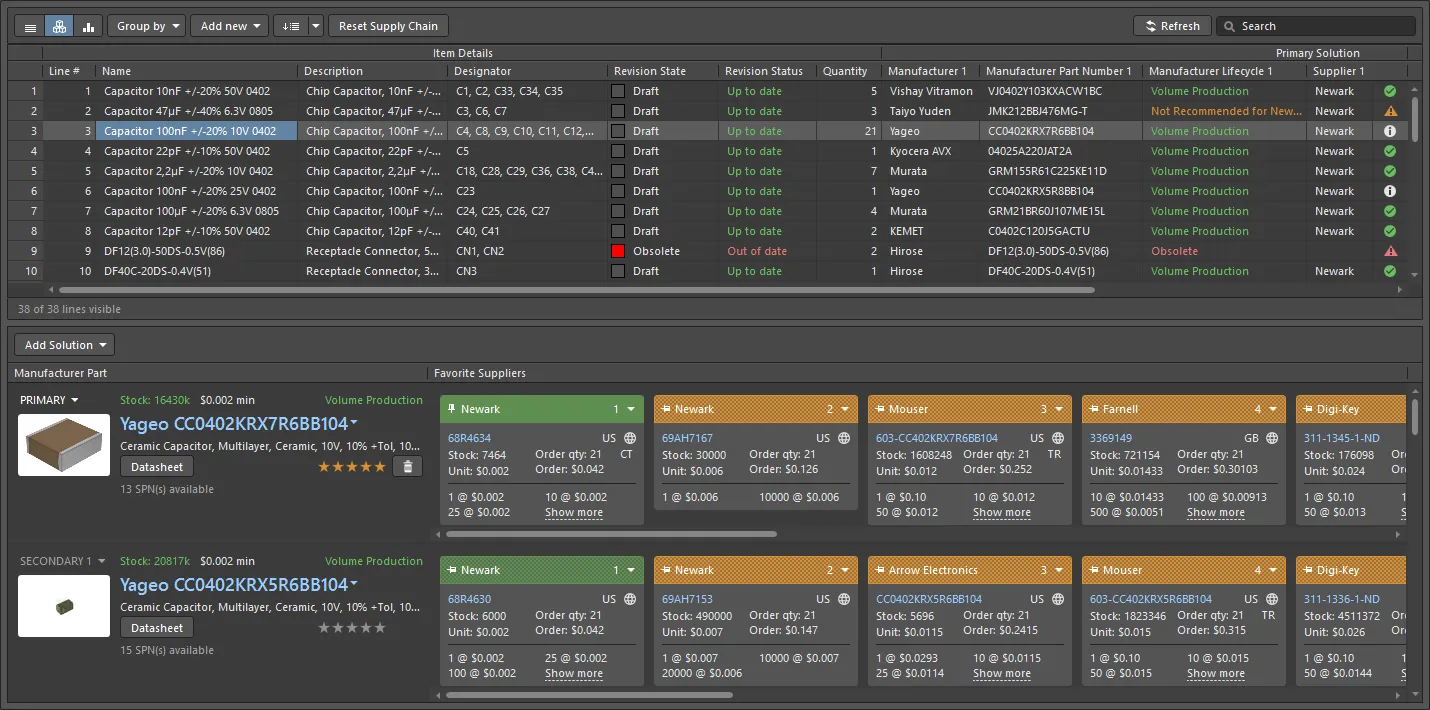
ActiveBOM presents the list of Items in the grid at the top, with the supply chain status of the selected Item shown below.
Note that the Component's
Revision State will not be displayed in the ActiveBOM when connected to a Standard
Altium 365 Workspace.
Managing the Components
Not all design components are crafted to the same standard. In days gone by the component started as a simple symbol in a symbol library, with qualifying details such as the value, the footprint and the manufacturer part number, being added during the design process. An easy and flexible system for an individual designer, but a nightmare to manage and maintain in a team, over time. Why was the manufacturer part number changed? who changed it? will the looser tolerance on that new part work in all the products that the part is used in? - there's a long list of potential issues awaiting the design team when their components are created and organized in this way. Altium refers to these components as unmanaged components.
As the design community came to understand the hazards of working with components in an ad-hoc manner, better approaches were developed. The design teams developed checking and sign-off processes for the design components and built databases to better manage the components used in their designs. The design-software developers helped by delivering better ECAD library systems, such as database libraries, which allow the design component to couple to the component record in the company database. But these solutions were custom-crafted and often required the design team to interact with and manage the design data through multiple software tools. And they also did not solve the ultimate question - we're just about to go to production, is that part actually available??
Altium has a solution to the entire, idea - to - purchasable part challenge. From the design component with revision control and lifecycle management, through to supply-chain selection with real-time pricing and availability, all aspects of the entire component management process are handled from within the design software, by using managed components, stored in a Managed Content Server.
► Learn more about Managed Components
Manufacturer-centric Solutions for both Managed and Unmanaged Components
Design components that are stored in an Altium Managed Content Server are referred to as managed components. As well as delivering full revision history and lifecycle management, another strength of using a Managed Content Server is that it allows the design component to be coupled to the supply chain, in real-time. This mapping from the design part to the manufactured part is done in a Part Choice. From the manufacturer and part number details stored in the Part Choice, the software can use the Altium Cloud Services to access detailed and up-to-date supply chain information for that part.
Components not placed from a managed content server are referred to as unmanaged components. While these parts do not have Part Choices defined, they are still supported by ActiveBOM. Since unmanaged components do not come with links through to the supply chain, those links can be defined in ActiveBOM instead. ActiveBOM can search the parts for suitable manufacturer details in the existing component parameters. If a design part does not include sufficient manufacturer details, then the designer can define manufacturer links directly, in the BomDoc.
Creating Solutions
ActiveBOM manages the mapping from the design component (part) to the part that is purchased. For each part used in the project, the linkage between:
- the design component,
- and the manufacturer of the part to be fitted to the board,
- and the available suppliers of that part,
is presented as a Solution in the lower region of the ActiveBOM interface.
Your objective is to have a Solution for each unique part used in your design. This Solution information is transferred into the BOM, providing the information needed to purchase the components.
In a managed component each Part Choice becomes a Solution - coupling the design component to the manufacturer part, and the available suppliers.
Where does the supply chain information come from?
The key information in a Solution is the manufacturer name and part number. Through the Altium Parts Provider, ActiveBOM uses the manufacturer information to access supply chain details from an extensive list of suppliers, funneling back real-time details such as price, stock levels, and minimum order quantities, into each Solution.
Solutions for Managed Components
For a managed component, the linkage between the design component and the real-world part is defined as a Part Choice. The advantage of using a Part Choice to couple the design component to the manufacturer part is that it means the design component does not need to have manufacturer or supplier details embedded in its parameters. The Part Choice can be defined independently and updated as needed, and multiple Part Choices can be defined when required.
In ActiveBOM, each Part Choice defined for a component automatically presents as a unique Solution. As well as detecting existing Part Choices, new Part Choices can be added directly in ActiveBOM, and Part Choices can also be ranked in ActiveBOM's Edit Part Choices dialog. For managed components, these Part Choice updates are stored back in the Managed Content Server.
Part Choices can be ranked and additional Part Choices can be added in ActiveBOM, these Part Choice updates are stored in the Managed Content Server.
Solutions for Unmanaged Components
ActiveBOM also supports creating Solutions for unmanaged components, that is, components placed from a company file-based library (for example; *.SchLib, *.IntLib, *.DbLib, *.SVNDbLib).
Since unmanaged components do not support Part Choices, ActiveBOM offers the following mechanisms to connect them to the supply chain:
- Firstly, ActiveBOM can be configured to detect manufacturer part details embedded in the component parameters and create a Solution using that information. Click the Manufacturer Link button in the ActiveBOM Properties panel to configure the parameters that are used for this.
- ActiveBOM also supports Supplier Links, a feature where supplier name and supplier part number details are added to the schematic component. ActiveBOM creates a Solution for the manufacturer part identified from the specified supplier details. The downside to Supplier Links is that the supply chain is limited to the specified supplier, other suppliers of that part are not included. Be aware of this limitation if you choose to use Supplier Links.
- The third level of support for an unmanaged component is to add a Solution directly in ActiveBOM. In previous versions of ActiveBOM, Solutions for unmanaged components were added as Supplier Links, limiting the supply chain data to the specified supplier. Now when a Solution is added to an unmanaged component in ActiveBOM, it is added as a Manufacturer Link (manufacturer name and part number). This gives the Solution full supply chain support, the software can use the Altium Parts Provider to access detailed and up-to-date supply chain information for all current suppliers of that part - just like a Part Choice defined for a managed component.
- The fourth level of support is for a BOM Item that is not returned by the Altium Parts Provider. This type of item is referred to as a Manual Solution, these require the designer to enter all of the required details, such as the manufacturer, the manufacturer part number, supplier details, and so on.
Manufacturer Links defined in ActiveBOM have full access to the supply chain.
Working with Components in Altium Designer
Components are the foundation of every electronic design. When you're creating a design you can divide the components into two groups - the components you already have, and the components you still need to get. Altium Designer includes a panel for working with each of these component-groups.
Both panels include powerful search capabilities. Enter a query in the main Search field to perform a string search, or progressively refine the search criteria using component type Categories and smart Filters – or use both capabilities together.
The Components Panel
The Components panel is used to access your own collection of components, both managed and unmanaged. Unmanaged components can be stored in any of the available file-based library types (SchLib, IntLib, DbLib, etc.,), and managed components can be stored in any of the managed content storage systems (Altium Vault, Server, etc.).
Your managed (1) and unmanaged (2) components are accessed through the Components panel.
► Learn more about working in the Components panel
► Learn more about the various component storage options
The Manufacturer Part Search Panel
There are millions of electronic components available today, through thousands of suppliers, from hundreds and hundreds of manufacturers. Altium appreciates how time-consuming it is for the designer to research the components they need in their designs, checking not only the performance characteristics but also the price and availability, of the many components they need in their design.
To help with this the Manufacturing Part Search panel has been developed - providing a designer's window into the component world. Harnessing the power of the Altium Parts Provider, the panel gives instant access to a vast array of components from a broad range of manufacturers.
Use the Category list and Filters to quickly locate the required component, then check the stock levels and price breaks for the various suppliers.
The icon indicates that there are Altium Designer models available for this component.
► Learn more about working in the Manufacturing Part Search panel
Creating the BOM Document
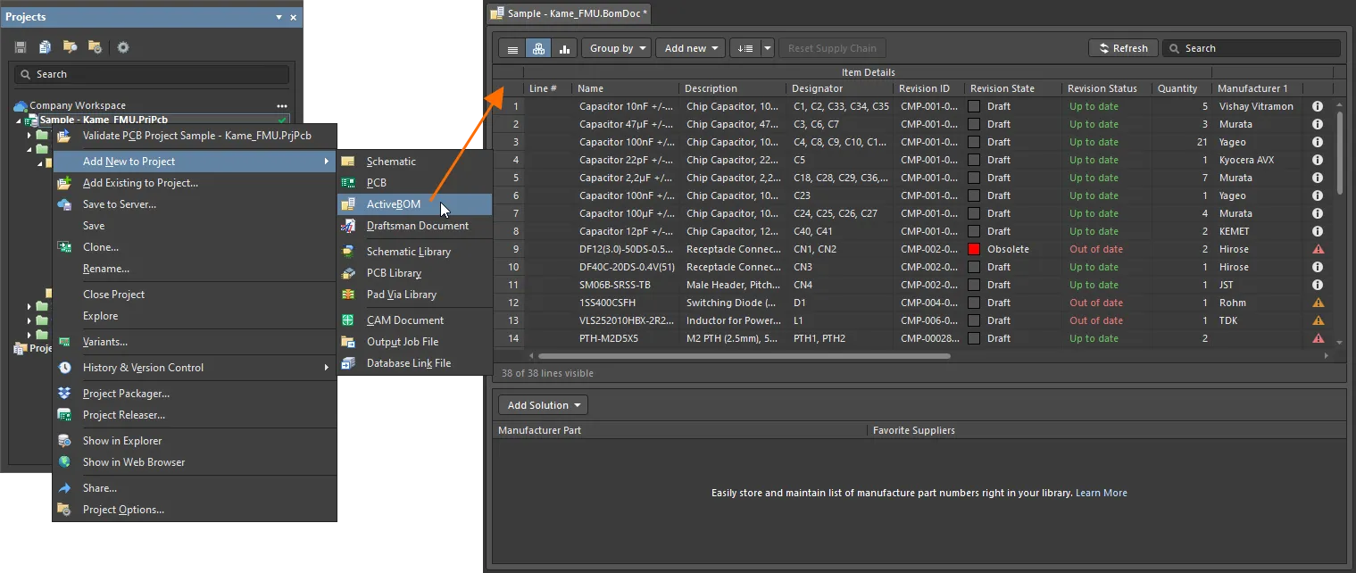
ActiveBOM's working BOM document is referred to as a BomDoc. Add a new BomDoc to the project via the File » New sub-menu, or right-click on the project in the Projects panel. Note that each PCB project can only include one BomDoc.
When you add a new BomDoc to your project, the schematic is automatically compiled and all of the existing components are listed in the BomDoc. For managed components that include Part Choices, Solutions will be detailed in the lower region of the interface, as explained in the Understanding the Solution section below.
As additional components are placed on the schematic they are automatically added into the BomDoc. Additional BOM Items and additional parameters can also be manually added directly in ActiveBOM, via the Add new button, located above the component list. Refer to the Custom BOM Items and Columns section to learn more.
- When the BomDoc is opened the project is automatically compiled, and the list of design parts and their supply chain details refreshed. This can take some time when a large design is initially opened and can result in the BomDoc being flagged as a modified file, even though it was just opened.
- Each PCB project can only include one BomDoc.
The BOM Items List
The upper region of the BomDoc is a tabular list of all of the components detected in the PCB design project, as well as additional BOM Items you have added directly into the BomDoc. This region is referred to as the BOM Items list.
The components, or BOM Items list, displayed in the Base view.
There are 3 view modes available to display the BOM Items. Select the required mode using the buttons located above the list:
Flat view - a row for every component.
Base view - a row for each unique component in the project, the Designator column lists the designators of all components of this type. Multiple presentation options are available for grouped designators. Select the required Designator Grouping mode in the Properties panel.
Consolidated view - used when the project includes variants, to display a consolidated BOM for all variants.
BOM Items List Editing Features
Many of the configuration and BOM display options are set in the ActiveBOM Properties panel.
Identifying Identical Components
To be able to group identical components in the Base and Consolidated views, ActiveBOM uses the following mechanisms:
- For managed components - by
DesignItemID
.
- For unmanaged components - by
DesignItemID
, and also by the component parameters enabled in the Component Grouping dialog. This approach allows designers to create generic unmanaged components in the library, and then populate them with specific component detail once they have been placed. The default parameters enabled in the Component Grouping dialog are Comment
, Description
, and Value
. Click the Component Grouping Edit button in the ActiveBOM Properties panel to open the dialog. Note that this button is only available when there are unmanaged components in the design.
Notes about Component Grouping:
- The Component Grouping dialog is used to identify identical components so they can be grouped. Although other parameters/properties, such as PCB component properties, can be listed in the Component Grouping dialog, only component parameters can be used to define identical components.
- If you want to group components in the BomDoc or in a custom BOM for some other purpose, for example to group top-side components and bottom-side components, switch to the List view and then use the Group by button in ActiveBOM ( show image ), or use the Column grouping feature in the Report Manager ( show image ). The parameters available in the ActiveBOM Group by dropdown list are those parameters that are currently set to visible in the Columns tab of the Properties panel.
The Column Groups
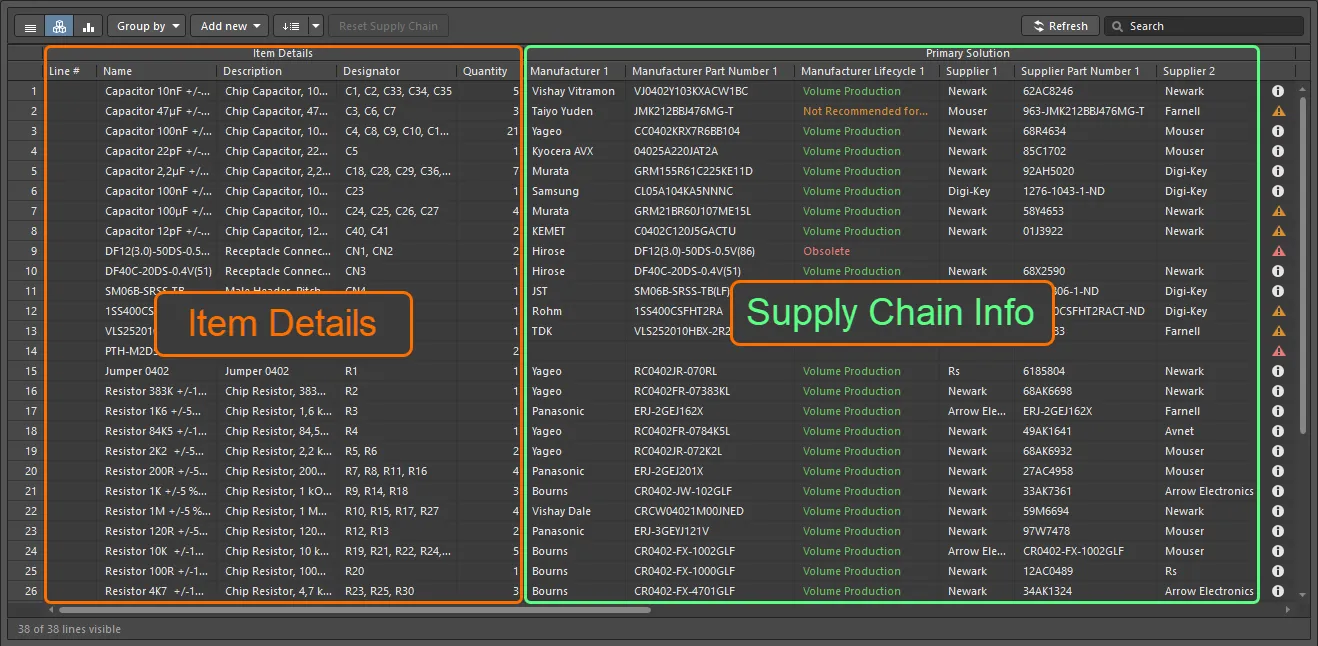
The ActiveBOM components list has distinct groups of columns that present in each view mode, the image above shows the Base view.
The BOM Items grid is clustered into the following major groups:
- Item Details (orange highlight in the image) - these columns display parametric component details, such as the Designator, Description, Library Reference, and other component parameters.
- Solutions (cyan highlight in the image) - the highest-ranked manufacturer + supplier(s) from the Supply Chain. The number of solutions (manufacturer parts), and the number of suppliers of each solution, are configured in the ActiveBOM Properties panel - these are indicated by a solid, colored banner in the supplier tile. Ranking is automatic, and can also be manually defined, as discussed in the Understanding the Solution section below.
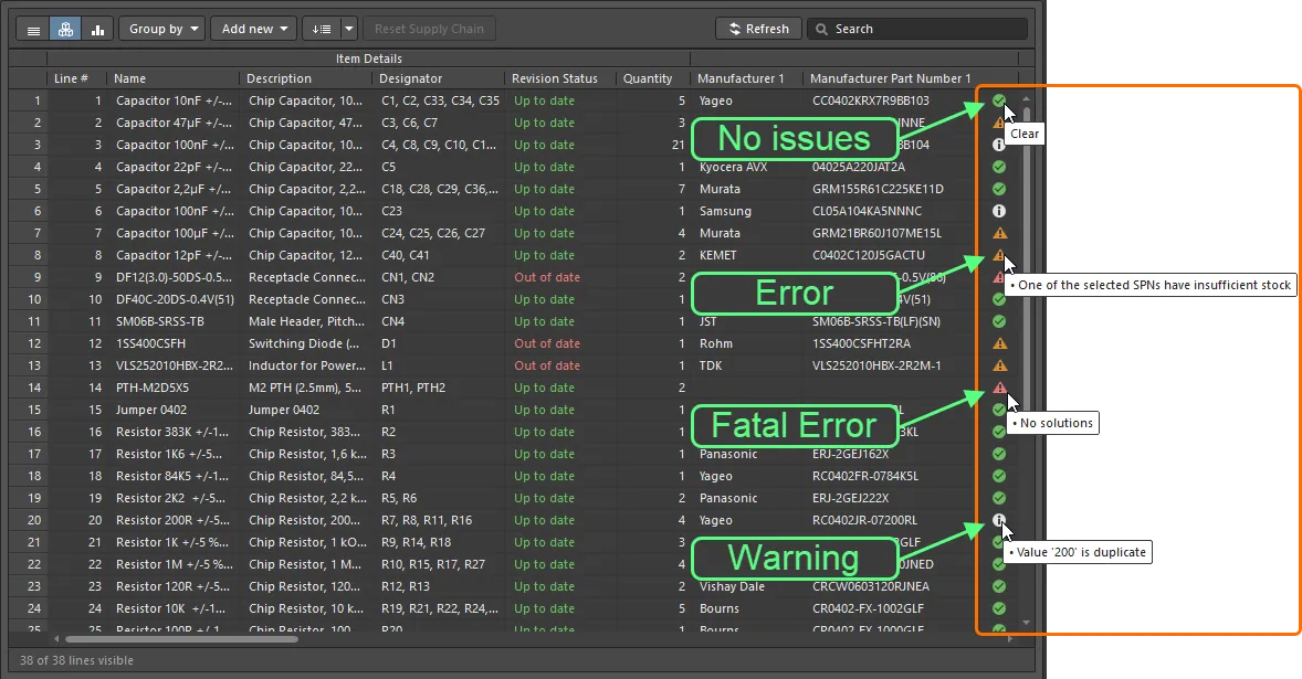
- BOM Status (green highlight in the image) - an indication of the current risk associated with each component. Hover over an icon for a description, or alternatively, enable the detailed BOM Status column in the Properties panel to display the description.
- Variant Details - in Consolidated View, an additional Group, titled Variants, is added just before the BOM Status column. This group includes a column for the base design, and one for each variant, displaying the quantity (per unit) of each component. Refer to the Working with Variants section for more information.
The display of columns and the definition of Aliases can be managed in the Columns section of the ActiveBOM Properties panel. To add a custom row, component, or column, click the Add new button above the component list.
Custom BOM Items and Columns
BOM management for a PCB design project requires the management of components and BOM Items beyond those placed in the schematic and PCB. There are many cases when custom BOM Items or parameters will be used in the PCB design project. For these situations, ActiveBOM supports adding additional BOM Items and columns (parameters), which can then be included in the generated BOM:
- Custom row - an easy way to add a custom BOM Item that needs to be accounted for in the design (bare board, glue, etc). All fields in a custom row are user-defined. Custom rows are not managed by ActiveBOM, for example, if the quantity is set to 3, there will not be 3 separate items displayed in Flat view. Supply chain searching is also not supported for custom rows.
- Custom column - additional BOM column, managed in ActiveBOM, that can contain any user-defined text.
- Custom Item - an additional BOM Item, this is typically for those items that will be needed but are as yet not fully known or do not yet exist in the library. This allows these items to have their cost included in the overall board cost estimation.
- Managed Component - an additional BOM Item, that is managed manually in the BOM document. The Component Search dialog will open, listing the components in the currently connected Managed Content Server. The chosen additional BOM Item can also be changed at any time via the right-click Operations sub-menu.
After adding a Managed Component or a Custom Item, right-click on it and select the Operations » Add Instances of command to define the designator prefix and separator, and the quantity. All other parameters, such as the Description, can be edited directly in the BOM Items grid.
To edit the designator, or to remove an instance of a Managed Component or a Custom Item, right-click on it and select the Operations » Edit item command, the Change / Remove dialog will open.
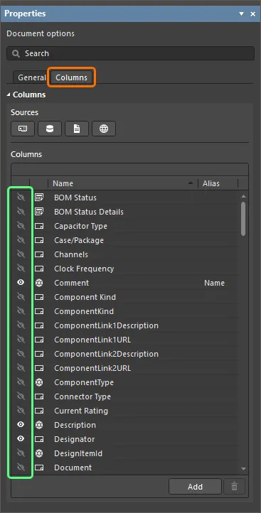
- Use the Column tab of the Properties panel to quickly find, view and manage column visibility, name or aliases. When there is an alias defined for a column name, this is displayed in the BOM Items grid.
- All additional BOM Items and parameters added in ActiveBOM are available for other BOM-outputs, and also via the software API.
Data Sources
The default data sources available in ActiveBOM are the schematic component parameters ( ), the server component parameters for managed Items ( ), and data provided by ActiveBOM ( ). From these sources, ActiveBOM generates the main project BOM Item grid. Data sources are enabled and their display controlled in the Columns tab of the ActiveBOM Properties panel.
By enabling the relevant Sources button (above the Columns list), the BOM can also include information taken from the following additional data sources:
The PCB - enable these to include PCB location/rotation/side of board data in the available Columns, for each of the components.
Database - to load additional component parameters from an external database (via *.DbLib, *.SVNDbLib, or *.DbLink).
Altium Cloud Services - enable this to access a broad range of additional component data, for those BOM Items that have been identified by the Altium Parts Provider and show a supply chain solution.
Document Parameters - enable this to include all detected schematic document parameters, across all schematics in the PCB project in the available Columns.
The source of each parameter is indicated by the icon in the list of columns.
Data Source Parameter Priority
If the same parameter is present in more than one data source, the following priorities are applied in ActiveBOM (highest to lowest):
- BOM
- PCB
- Documents
- Server
- Database
- Cloud
- Schematic
- Manual
- The buttons above the Columns list enable/remove that data source, if a source is disabled then all data from that source is removed from the grid.
- The checkboxes below the Columns list are convenient filters for the Columns list, use these to add/remove a data source from the Columns list, without removing the data from the grid.
As well as using the Altium Parts Provider it is also possible to connect to an existing company database via an ODBC connection. This is achieved by enabling the Custom Parts Provider Synchronization feature in Altium Designer (select the Custom Data Synchronization option in the Configure Platform page (under Importers\Exporters)) and enabling it as a provider in the Data Management - Parts Providers page of the Preferences dialog. This feature effectively allows the company database to behave as a Managed Content Server parts provider. To learn more, read about Custom Database Parts Providers on the Supply Chain Management page or watch this video.
Line Number Column
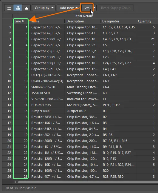
For PCB designs with assembly drawings, or for BOM data exchange between design engineers, cost engineers or purchasing specialists, the BOM line number (BOM Item position No) is a simple method used to individually distinguish BOM lines, which can then be used to explicitly identify or find the corresponding callout, component and depiction in the design.
As the project BOM data source, ActiveBOM supports user-defined Line #’s for the project BOM and has both manual and automatic Line # (BOM Item position No) management features.
- To automatically set the position number for the all project BOM Items (components), click the Set Line # button. Line numbers are displayed in the Line # column, in the Item Details group of columns. Click the dropdown icon on the right of the button to open the Line # Options dialog, where the start and increment values can be defined.
- To manually change Line #'s, switch to Base view mode then select the required cell(s) in the Line # column and:
- Press Delete on the keyboard to clear the cells, then
- manually type in new values, or
- paste a range of values from the Windows clipboard.
- To renumber or continue numbering from a custom added number click on the required item Line # cell, then click the Set Line # button. The Line Numbering dialog will open, where you can Continue numbering or Renumber all. The base and increment values last defined in the Line # Options dialog are used to calculate the numbers added, if required you can enter a seed value in the selected Line # cell to define the start number.
The Continue numbering variation of the Line numbering dialog opens when SOME of the line numbers in an ActiveBOM document (*BomDoc) have already been defined.
The Renumber all variation of the Line numbering dialog opens when ALL of the line numbers in an ActiveBOM document (*BomDoc) have already been defined.
The Line # management features are available in Base view mode.
Configuring and Saving the Display of the BOM Items Grid
Like any good spreadsheet application, the BOM Items grid can be configured to suit your requirements. As well as the traditional column ordering and sorting features, the current configuration can be saved as a BOM Set.
Grid configuration features
- Display / hide any column - via the Columns feature in the Properties panel. Use the Search field at the top of the panel to quickly locate a column.
- Change the order of columns - click and hold on the column title and drag and drop.
- Change the width of a column - hover over the column edge in the title region and click and drag (look for the cursor), or double click at that location to auto-size to suit the column's contents.
- Sort the entire grid by a column:
- Click the column title to alpha-numerically sort the grid by that column's contents.
- Click a second time to sort in the reverse direction.
- Hold Shift and click on another column title to sub-sort by that column's contents.
- Filter the grid by a specific value - click the Filter icon to filter the grid by a value used in that column.
- Store the configuration as a BOM Set - more on this below.
Working with BOM Sets
Any number of BOM Item grid configurations can be saved - each of these is referred to as a BOM Set. After configuring the grid to your requirements, click the Add button in the BOM Sets region of the ActiveBOM Properties panel to add a BOM Set to the list.
Click the eye icon to enable a BOM Set.
BOM Sets are configured in the ActiveBOM Properties panel.
The preferred BOM Set can be selected during BOM generation in the Report Manager.
BOM Verification
ActiveBOM includes a comprehensive set of BOM checks, that is automatically performed each time the BOM is updated.
BOM Status
Each BOM Item is checked for violations and its status is displayed in the BOM Status column. This column is always visible on the right side of the BOM Items list, displaying an icon that indicates that item's status. Note that a BOM Item can fail more than one of the BOM checks, the icon indicates the most severe failure.
BOM Status Icons:
- Clear - component has solutions, these solutions have suppliers with sufficient stock, and at least one solution has been ranked.
- Warning
- Error
- Fatal Error
Hover over the icon for a summary of that part's status. Alternatively, enable the display of the detailed BOM Status column to display detailed information. The column can be enabled either via the ActiveBOM Properties panel, which includes a handy search box or by right-clicking in the column header area of the BOM Items list then choosing the Select Columns command.
Configuring the BOM Checks
The BOM Items are automatically checked for:
- Violations associated with Design Items: this includes tests such as parts whose BOM parameters do not match the library parameters (ambiguous parameters), and duplicate designators.
- Violations associated with Part Choices: this includes tests such as an unranked MPN (system assigned ranking only), no suppliers, or a missed target price.
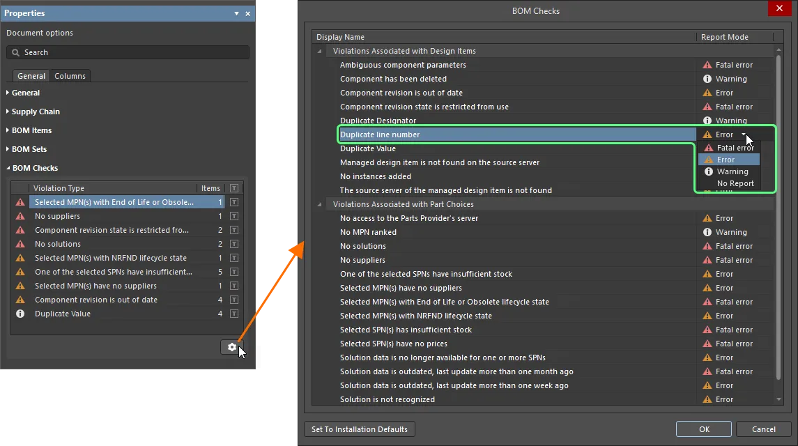
The severity level (report mode) of each BOM check is configured in the BOM Checks dialog. Click the Gear icon below the BOM Checks detected violations list in the Properties panel (as shown in the image below) to open the dialog.
The '
Component revision state is restricted from use' violation will not be displayed when connected to a Standard
Altium 365 Workspace.
Filtering the BOM Items List by BOM Status
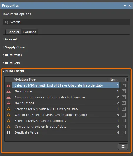
The Properties panel displays a list of detected BOM check violations that are present in the current BomDoc. Click the Filter icon (as shown below) to filter the main BOM Items list so that it only displays those BOM Items that fail that BOM check. Note that a BOM Item can fail multiple BOM checks.
Click to filter out all BOM Items except those that fail this BOM check.
Click the Gear icon to configure the BOM Checks.
Use the Filter feature to quickly identify all BOM Items that fail a specific BOM Check.
Understanding the Solution Details
Component selection is often a process of juggling availability, unit price, and manufacturing volume. One of the great strengths of ActiveBOM is its ability to bring detailed, up-to-date supply chain information right into the design environment. Having access to this information means the designer can easily monitor their component choices and adapt these as required.
The Manufacturer Details
If a design component includes a recognized manufacturer and manufacturer's part number (referred to as the MPN), ActiveBOM will present this as a Solution in the lower region of the ActiveBOM interface (each row is a solution). For each Solution, ActiveBOM will automatically access the Altium Cloud Services and attempt to locate supply chain information about that part. A key feature of the cloud services is the Altium Parts Provider, which aggregates live parts information from an extensive list of external suppliers, funneling back key information such as supplier, price, stock levels, and minimum order quantities, into ActiveBOM.
Each of the rows displayed below the BOM Items list is referred to as a Solution, with the manufacturer part detailed on the left, with each of the available suppliers returned by the Altium Parts Provider detailed on a separate color-coded tile.
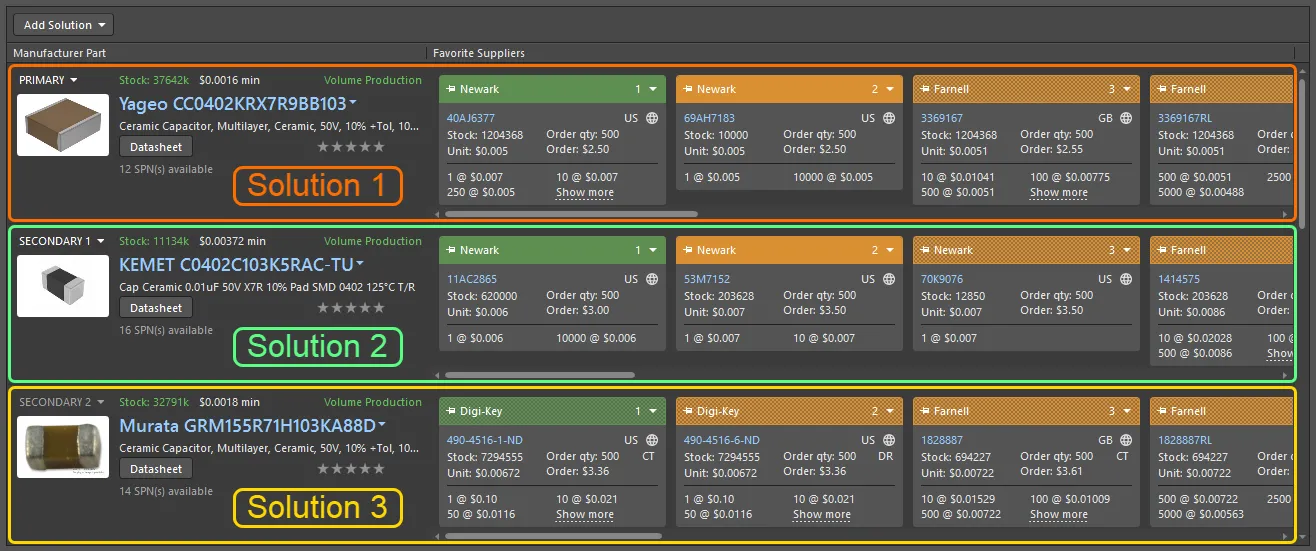
Each row represents a Solution - a manufacturer part and the available suppliers of that part.
Refer to the Managing the Solutions section to learn more.
MPN Information
- Manufacturer details:
- Part image
- Manufacturer name
- Manufacturer Part Number (linked to the part on the Manufacturer's website)
- Description
- Priority of solution (Primary, Secondary 1, Secondary 2, etc.,)
- Stock total: sum of the stock available from the favorite suppliers (global availability). Red if stock < order quantity.
- Minimum unit price. Red if no prices or price = 0
- Manufacturer Lifecycle: data from Altium cloud services, where:
- Gray = Default, unknown or no information
- Green = New or Volume production states
- Orange = Not Recommended For New Designs
- Red = Obsolete or EOL
- Link to datasheet (Octopart)
- Quantity of available favorite Suppliers
- User Rank, click to set
Interpreting the Lifecycle State
Use the lifecycle status to help select the most suitable part.
The current lifecycle status is displayed for each solution (as shown in the image above).
The lifecycle status is designed to be used as an indicator, for a number of reasons:
- Altium maintains a database of many millions of components, produced by thousands of component manufacturers. Since there is no single, consistent method used by those manufacturers to reflect a component's lifecycle state, the status is based on information aggregated from manufacturers, global distributors, and global sales analysis.
- A part is only reported as EOL or Obsolete when there is at least one authorized distributor or manufacturer that has confirmed this status.
- Determining the Not Recommended for New Design (NRND) status is more complex. Manufacturers sometimes just report if a part is active or not, and may not give advance warning that a part is to be discontinued or replaced. Therefore this lifecycle status does not always concur with the status provided by the manufacturer. The status algorithm uses various information, including real-time and historical stock availability from all distributors, to try to determine the availability of the part. Parts which have consistently poor availability (when they have been generally available in the past), or cannot be sourced over a period of time after having previously had good availability, will eventually be flagged as NRND (if they are not already EOL or Obsolete).
- The idea of the lifecycle status indicator is to provide simple-to-understand information that helps you to make more informed decisions about a part, by highlighting those parts which may be problematic. However, due to the sheer volume of data and number of components that are managed, there is always a chance that the Altium status lags behind the instantaneous manufacturer status, and is therefore not up-to-date. It is not possible for Altium to guarantee the accuracy of the lifecycle status, it is recommended that if there is any doubt that you double-check with the manufacturer for authorized lifecycle information.
Refer to the MPN Information collapsible section just above for details about the colors used to reflect the lifecycle status.
Ranking the Solutions
If multiple manufacturer parts are available - meaning there are multiple solutions - the solutions are automatically ranked from highest to lowest based on the part's availability, price and manufacturer lifecycle state.
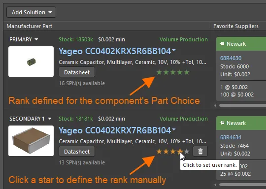
If you prefer to use a lower-ranked solution, for example, to use a specific manufacturer, you can override the automatic ranking by defining a User Rank, using the star feature, as shown in the image below.
Click on a star to define a user ranking for a solution.
- The default settings for BOM Checks will display a warning flag against all unranked parts. This is done to encourage the designer to examine the automatic ranking and accept or override as they see fit.
- User-defined ranks (and manually assigned SPN priorities) can be cleared for selected BOM Items by clicking the button.
- Rankings assigned in the BomDoc are saved in the BomDoc. For managed components, you can also rank the Part Choices in the Edit Part Choices dialog (Add Solution » Create/Edit PCL), rankings defined in this dialog are stored in the managed content server.
- Ranking defined in another BomDoc can also be applied in the current BomDoc, run the Tools » Import Ranks command then select the required BomDoc. The parts in the chosen BomDoc will be compared against the parts in the current BomDoc, and supply chain rankings imported for BOM Items whose DesignItemIDs match. When DesignItemIDs match the ranking of existing MPNs in the solutions will be updated, and additional MPNs that are detected in the imported BomDoc will be added as additional solutions. Note that only SPNs that were pinned in the imported BomDoc will automatically appear after importing. Click the Refresh button to force an update of all SPNs. Learn more about the Import Ranks command.
The Suppliers
To the right of the manufacturer part details are the available suppliers that have been returned by the Altium Parts Provider, with each supplier detailed on a separate tile. These tiles are also referred to as the SPNs (Supplier Part Numbers).
The SPNs are automatically ranked by availability and price. Each SPN tile includes a colored banner, the color reflects the risk associated with choosing that SPN (detailed below). Because the availability and price data can be refreshed at any time from the Altium Parts Provider, the order of the SPN tiles can change.
The SPN tile includes detailed information about the part and its availability.
SPN Tile Information
- Tile banner, including locking pin, supplier name, tile sequence dropdown, where the banner color indicates:
- Green = Best
- Orange = Acceptable
- Red = Risky
(solid banner indicates a used solution/supplier, configured in the Supply Chain section of the Properties panel)
- Supplier part number (linked to the part on the Supplier's website)
- Country code for the Supplier location (ISO alpha 2).
- Source of the part information (hover for details). Color indicates:
- Gray = Default, updated less than one week ago
- Orange = 1 week < last update < month ago
- Red = last update > 1 month ago
- Stock, red if available stock < order quantity
- Unit price: red if no price available or price = 0 (currency is set in the ActiveBOM Properties panel)
- Packaging of supplied parts; hover for details.
- Order quantity, orange if Minimum Order Quantity (MOQ) > order quantity, information on any surplus displayed in the tooltip
- Order price (Unit Price * Order Quantity), red if 0 (meaning no stock or no unit price)
- Available price breaks, with Minimum Order Quantities
The available suppliers are defined on the Data Management - Parts Provider page of the Preferences dialog for this installation of the software. If The Data Management - Parts Provider Preferences are changed (for example, a supplier is excluded), the ActiveBOM document must be reopened in order to apply the changes.
The available suppliers can also be filtered down in an ActiveBOM in the Favorite Suppliers dialog.
Ranking the Suppliers
The default state for a new BOM Item is that the Suppliers are ranked automatically. Note that this ranking can change over time, as the price and availability of a particular part change. If required, you can lock an SPN tile to a specific position by clicking the pin icon on the left of the SPN tile banner. The automatic ordering of the SPNs can also be manually overridden, use the drop-down on the right of the tile banner to set the required position. If you use the dropdown to manually set the position of an SPN tile, the locking pin is automatically applied.
To learn how to apply supplier-priority to the ranking, refer to the Configuring the Available Suppliers section.
Managing the Solutions
Through a tightly coupled set of services and teams, Altium maintains a vast catalog of components and component supply chain data. This data is delivered as part of the Altium Cloud Services.
As well as supporting managed components that already include supply chain information, such as those placed from an Altium Managed Content Server, ActiveBOM is also able to search for supply chain data for other components.
To summarize, the components you use in your design can access supply chain data in the following ways:
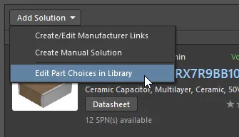
- Parts placed from the Manufacturer Part Search panel or a company Managed Content Server (managed parts) - Parts placed from the Manufacturer Part Search panel or a company Managed Content Server are already linked to comprehensive supply chain data, via their Parts Choice List. Additional Part Choices can be added in ActiveBOM, click the button then select Create/Edit PCL from the menu. Click Add in the Edit Part Choices dialog to create a new link and the Add Part Choices dialog will open - refer to the Adding a New Solution section to learn more.
- Parts placed from local libraries that include manufacturer part information (unmanaged parts) - For parts that already include the manufacturer name and part number, for example, parts placed from a company Database Library which include this information, ActiveBOM can search for that part through the Altium Parts Provider. To do this, ActiveBOM needs to know which component parameters hold those manufacturer details, these are defined by clicking the Manufacturer Link button in the ActiveBOM Properties panel. Refer to the Configuring the Manufacturer Link Fields section for more information.
- Parts placed from local libraries that have no supply chain information (unmanaged parts) - These parts can have supply chain information added:
- Directly in ActiveBOM - by adding a Manufacturer Link. Click the button and select Create/Edit Manufacturer Links from the menu. Click Add in the Edit Manufacturer Links dialog to create a new link and the Add Part Choices dialog will open - refer to the Adding a New Solution section to learn more.
- During design capture - using the Supplier Links feature. Supplier Links can be added to an existing schematic component by right-clicking on the component on the schematic and selecting Supplier Links from the context menu, then locating the required part in the Add Supplier Links dialog and selecting the required supplier of that part; or by locating the part in the Manufacturer Part Search panel and right-clicking on the required supplier and selecting the Add Supplier Link command, then clicking on the schematic symbol on the schematic sheet. Note that Supplier Links are locked to that supplier, ActiveBOM cannot source that MPN from other suppliers.
- Directly in ActiveBOM - by creating a manual solution. Use this approach to add supply chain information for special items such as glue, fasteners or other mechanical items.
Each solution's supply chain source is shown in the Manufacturer Lifecycle n column.
Click the button to update all available supply chain data, for all components in the ActiveBOM.
Configuring the Available Suppliers
Supply chain data is delivered through the Altium Parts Provider. The Altium Parts Provider can access details for a vast number of component suppliers, distributed all over the globe. The set of available suppliers is configured at two levels:
- For this software installation - configure the suppliers in the Data Management - Parts Provider page of the Preferences dialog.
- For the current project - click the Favorite Suppliers List button in the ActiveBOM Properties panel to define the suppliers you want to be available in this project. Refer to the Set Up Part Providers dialog page for more information.
Prioritizing by Supplier
ActiveBOM's default behavior is to select suppliers for the chosen manufacturer part based on item availability and price, from those suppliers enabled in the Favorite Suppliers dialog. To prioritize supplier over price, enable the Use supplier priority checkbox in the Favorite Suppliers dialog. When this option is enabled, only solutions available from the enabled suppliers are listed. The exception to this is user-defined manual solutions, which are always shown.
Configuring the Manufacturer Link Fields
If you have unmanaged parts (parts that have not been placed from a Managed Content Server or the Altium Content Vault), ActiveBOM can search for suitable suppliers automatically if the components include the manufacturer and part number details somewhere in their parameters. For ActiveBOM to be able to query the Altium Parts Provider for suitable supply chain details for these unmanaged parts, it needs to know which of the part's parameters hold the Manufacturer Name and the Manufacturer Part Number. These are configured in the Define Manufacturer Link Fields dialog, click the Manufacturer Link button to open the dialog. Multiple Name / Part Number parameter pairs can be defined.
Refer to the Define Manufacturer Link Fields dialog page for more information.
- Manufacturer Links can only be defined if the project includes at least one unmanaged component.
- To force ActiveBOM to recheck all components for possible manufacturer part details, click the button. Note that this search process can take some time when there are many parts.
Configuring the Number of Solutions and Suppliers
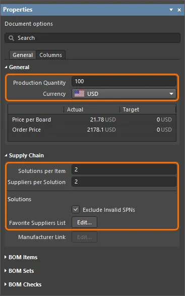
To ensure a smooth passage through the assembly process, many companies require all parts in the BOM to include multiple suppliers, and may also require that alternative parts are detailed. These requirements are configured by the options in the Supply Chain section of the Properties panel.
The Supply Chain options control how many Solutions to include, and how many Suppliers per Solution. Included supplier tiles have a solid color in their banner.
- The number of Solutions per Item option is used to control how many Solutions are to be included for each BOM Item. Each additional Solution is an alternate part. As this value is increased an additional group of columns labeled Secondary Solution n (detailing the manufacturer and the specified number of suppliers), is automatically added to the BOM Items grid. In the image above, the BomDoc is configured to include 2 Solutions for each BOM Item (light blue highlighting).
- The number of Suppliers per Solution option is used to control how many suppliers are detailed in the BOM Items grid for each part. As this value is changed the specified number of supplier columns is updated to suit. In the image above the BomDoc is configured to include 2 suppliers per Solution (green highlighting).
- The colored banner of each Supplier tile is used to indicate if that supplier is included - a solid banner color indicates that the Supplier is included in the BOM Items grid; a checkered banner indicates that Supplier is not included.
Exclude Invalid SPNs - enable this option to remove all Suppliers that are considered invalid (red banner). This includes parts that show: no stock, no prices available, or out of date price/availability data. Refer to The Suppliers section above for more details of where this information is presented on the Supplier tile.
Adding a New Solution
Adding and editing Solutions uses essentially the same process for both managed and unmanaged components. Regardless of whether you are adding a Manufacturer Link to add a Solution to an unmanaged component, or adding a new Part Choice to add a Solution to a managed component, search for the part in the Add Part Choices dialog.
To add a new Solution:
- Click the Add Solution button below the BOM Items list in ActiveBOM then select either Add/Edit Manufacturer Link (for an unmanaged component) or Add/Edit PCL (for a managed component).
- If you are adding a Manufacturer Link to an unmanaged component, the Edit Manufacturer Links dialog will open. To add a new link click the Add button; the Add Part Choices dialog will open.
- If you are adding a new Part Choice to a managed component, the Edit Part Choices dialog will open. To add a new Part Choice click the Add button; the Add Part Choices dialog will open.
A Manufacturer Link being added to an unmanaged component. If the selected part was a managed component, the Create/Edit PCL command would be used.
The Add Part Choices dialog:
- Gives you access to all of the parts available through the Altium Parts Provider.
- Opens pre-loaded with a search applied, using the Name field of the selected BOM Item (the schematic Comment property). Click the x button to clear this search term and enter a new one. The part parameter used for the search is defined in the Suggested Keywords section of the Data Management - Parts Providers page of the Preferences dialog.
- Has a similar layout and shares many of the features with the Manufacturer Part Search panel.
Searching for a Part
Utilizing Altium Designer's advanced component search engine, the Add Part Choices dialog can be used in a straightforward search mode by entering a query in the main Search field, or in its advanced faceted mode by progressively refining the search criteria using the Categories and Filters choices – or by using both capabilities together (referred to as a faceted search).
Use the Search field at the top of the dialog to locate suitable parts based on a search description.
For example: LED green clear 0603 SMD
Or use the Categories and Filters when you want to explore potential parts by toggling criteria on and off.
For example:
- First select a Category, such as
LEDs
,
- then Filter the LEDs category by the
Manufacturer
, Mount
, Case/Package
, and so on.
- Categories are accessed using the dropdown, as shown in the image above.
- Filters are accessed by clicking the button to display the dialog's Filters list. The contents of the Filters list change to suit the category of component being searched. Hover the cursor over the image above remove the Categories list and show the Filters list.
- Click on a column heading to sort the results by that column.
- Some of the Filter fields include text boxes to enter numeric values, press Enter on the keyboard to apply the value.
- If the results list does not update, click in the Search field and press Enter on the keyboard.
- The current search criteria defined by the chosen Category and enabled Filters list are detailed just below the search bar, click the small x icon to remove any of the existing search criteria.
- Hover the cursor over the vertical colored bar to display the current manufacturer's Lifecycle status; for example, Volume Production, EOL, etc.
► Learn more about Interpreting the Lifecycle State.
Altium Designer's sophisticated part searching capabilities are delivered through the Altium Parts Provider, which aggregates component information from the Octopart and Ciiva component portals. When available, it includes symbols and models, sourced from the Altium Content Vault.
Dialogs that support searching for components have a landscape mode and a portrait mode. As the dialog is resized the controls will re-arrange, so they may not present exactly as they are shown and described here.
Checking Supplier Data
Each manufacturer part that is returned in the search results includes two hyperlinks next to the image of the part.
Clicking:
- The upper-link opens detailed component information about that part on the Octopart website.
- The lower link opens detailed information about suppliers that carry that part, ordered by availability and price.
Click the link to reveal detailed SPN information, sorted by availability and price.
Each of the color tiles in the image above is referred to as an SPN (Supplier Part Number).
The SPN tile in the Add Part Choices dialog includes detailed information about the part and its availability.
SPN Tile Information
The tiles include various icons, hover the cursor over an icon for detailed information.
- Tile banner, including locking pin, supplier name, tile sequence dropdown, where the banner color indicates:
- Green = Best choice
- Orange = Acceptable
- Red = Risky
(solid banner indicates a used solution/supplier, configured in the Supply Chain section of the Properties panel)
- Supplier part number (links to that part on the Octopart website).
- Country code for the Supplier location (ISO alpha 2).
- Source of the part information (hover for details). Color indicates:
- Light Gray = Default, updated less than one week ago
- Orange = 1 week < last update < month ago
- Red = last update > 1 month ago
- Stock quantity; red if available stock < order quantity.
- Unit price is red if no price is available. Unit price is shown in the currency configured in the Properties panel.
- Packaging of supplied parts; hover for details.
- Available price breaks, with Minimum Order Quantities.
Creating a Manual Solution
Your design may require additional items, such as glue or screws, that will not be sourced from your preferred part suppliers. For items such as these, you can Add new » Custom Item and then create a manual solution for that item.
To create a manual solution, click the button and select the Create Manual Solution command. The Create Manual Solution dialog will open, where you can manually enter the manufacturer and supplier details for the part.
Additional SPNs can be added to the same solution, by creating another manual solution and entering the same manufacturer and manufacturer part number, as shown in the image below.
Manual solutions are indicated by the Manual solution string in the MPN region, and also by the icon on each SPN tile.
Editing or Deleting a Manual Solution
To edit or delete an existing manual solution, click the dropdown next to the manufacturer part number in the solution tile, and select the required command.
An existing manual solution can be deleted or edited.
When the Delete command is selected the supplier details are removed (the colored SPN tile disappears), but the manufacturer details remain. To remove the solution completely, first, remove the supplier(s). Once all suppliers have been removed a drop-down will appear just below the Manual Solution text in the Manufacturer details region of the solution. Use the Delete command in this menu to delete the solution completely.
Including an Alternative Part
To ensure the design can be built, most designers choose components that can be replaced by an alternative, if required. In ActiveBOM, this is achieved by adding additional Solutions (as just discussed), and then configuring the BomDoc to use multiple solutions using the Solutions per Item feature, as discussed earlier.
There may also be situations where an identical alternative is not available, but a functionally equivalent part can be used instead. For example, if there is a shortage of 6.3V capacitors, a 10V or a 16V capacitor of the same value could be used for this production run, instead.
Right-click to add an Alternative Item. Note the control on the left that is used to hide/display the alternative item. Hover the cursor over the image to display the BOM generation dialog, configured to include Alternative Items.
To select a functionally equivalent alternative part, right-click on the part then select Operations » Add Alternative Item from the context menu. The Component Search dialog will open, where you can search the connected Managed Content Server for a suitable alternative. Faceted searching is supported, refer to the Searching for a Part section to learn more about performing a faceted search in a dialog that supports it.
The BOM will include the quantity for both the original Item and the Alternative Item. A note column can be added into the BOM if required, to include instructions to the purchaser about the circumstances when each should be used.
Creating Groups of Alternatives
Another situation where it might be necessary to define alternatives is when there are multiple instances of the same part, but you do not want to source all of those parts from the same supplier.
For example, you have a large number of 10K resistors, and a large production run. To ensure supply, you would like to break this down and source the 10K resistors from four different suppliers when the BOM is processed. This can be done by splitting that part into four groups, with each group assigned a different Manufacturer/Supplier using the Rank feature.
Another situation where you might want to split a component into groups is when your design includes a component that requires a specific component from a specific manufacturer, but there are also other components that do not require the same restriction to a specific manufacturer. This can be achieved by creating a group for the special-case component to lock it to its specific manufacturer, then assign the remaining components to the other group.
To split a component into groups, right-click on the part in the BomDoc then select the Operations » Split Item (Add Alternatives Group) command from the context menu. The Edit Alternative Group dialog will open. Name the Alternative Group and enable the checkbox for each component you want in that group. The new group will appear as a separate line Item next to the BOM Item that was split, sharing the same Line #. The Alternative Group Name column will also appear, displaying the user-defined group name.
Line Item 3 has been split into 3 Alternative Groups, and each group has been assigned a different MPN by applying a suitable user-ranking to the preferred Solution.
Replacing a Component
It's not uncommon to identify an issue with a component when the BomDoc is being checked and made ready for ordering the parts. For example, the designer may have forgotten to finalize the selection of a component, or a component has gone EOL and the designer wants to explore the price and availability of potential replacements. Previously the only way to resolve this was to return to the schematic and edit the component, select a suitable part, then refresh the BomDoc.
Alternatively, you can change a component in the BomDoc, and then pushing that change back to the schematic via an Engineering Change Order. Right-click on the selected component(s) and select the Operations » Change <ComponentName> command. The Replace Component dialog will open, where the replacement component can be searched for.
When the Replace Component OK button is clicked the Engineering Change Order dialog will open, detailing the changes needed to synchronize the schematic with the BomDoc.
- The Replace Component feature searches for a new component in the currently connected managed content server. If a suitable component is not returned by your search, the dialog will display a link to open the Manufacturer Part Search panel, where you can right-click and either: Acquire the component to your own Managed Content Server (via the Create New Component dialog and Component Editor); or Download the component locally as an Integrated Library Package in a zip archive. These commands will only be available if the part you choose in the Manufacturer Part Search panel includes Altium Designer models (look for the icon).
- As an alternative to using the Search, Categories and Filters features in the Replace Component dialog, you can also right-click on a result and access the Find Similar Components dialog. The power of this dialog is that it takes the values of the component you right-clicked on and based on that, you can quickly locate multiple components that share common properties and parameters, over a range of values. ( show image )
- If the component change also affects the board design, an Update PCB should also be performed from the schematic.
► Learn more about Applying the ECOs
Working with Variants
ActiveBOM supports PCB projects that include Design Variants. The Design Variants feature allows a single base PCB design to be created, which is then populated (loaded) in different ways. Each different loading of the assembled board is called a design variant.
Working with Design Variants:
- Design variants are configured in the Variant Management dialog (Project » Variants).
- To examine a variant, double-click on its name in the project's Variants folder in the Projects panel, as shown in the image below.
ActiveBOM supports variants in the following ways:
- Display the BOM for a specific variant in Base view mode or Flat view mode
- Option to include the Not Fitted items in the BOM Items list
- Display a consolidated list of all parts used in all variants, in Consolidated view mode
- Define manual solutions for both base components and varied components
Variants in Base View Mode
For the selected variant, enable the Show Not Fitted option in the Properties panel to include these parts in the BOM Items grid. When this option is enabled, the Fitted column is automatically displayed in the Item Details.
In Base view mode the Fitted column will display either Fitted
or Not Fitted
. If a part is varied (an alternate part was chosen in this variant), the details of the alternate part are automatically displayed for that BOM Item.
Note that the current variant is displayed in the ActiveBOM status line.
Variants in Consolidated View Mode
The Consolidated view mode displays all components used in all variants. The Consolidated view offers the following features:
- If a component is varied, there will be a BOM Item for each alternate component that is used, with each of these BOM Items having the same designator. For example, in the image below, components DS1 and DS2 are each list twice, as the BGA variant uses a different colored LED from the TSOP variant. Component R1 appears three times because both the BGA and TSOP variants use a different resistor than the original in the base design.
- In Consolidated view mode, when the Show Not Fitted option is enabled the Fitted column will display
Fitted
or Varied
. Because the Consolidated view shows all components used in all variants, every component displayed is fitted in either the base or a variant.
- For each variant, there is a <VariantName> - Qty column (indicating how many of this component are used in this variant) and a <VariantName> - Price column, which is the unit price times the value in the quantity column.
- Because some designers create build documentation off the base design as well as the variants, there is also a Quantity column, reflecting the number of instances of this component used in a build of the base design. Hide this column if you do not generate build documentation off the base design.
- The grid in Consolidated view mode uses color to indicate a cell whose value is different from that cell's value in the base design, as shown below.
Color in a cell indicates that the value in this cell is different from the value for that cell in the base design.
To learn more about variants, refer to the Design Variants page.
Working Between the BomDoc, the Schematic and the PCB
There are two features available to help you work between the BomDoc, the schematic and the PCB design: Cross Select and Cross Probe. The behavior of these features is configured in the System - Navigation page of the Preferences dialog.
Both of these features can be used to locate the same component in other documents. The difference between Cross Select and Cross Probe is that Cross Select Mode selects the component in the target document but does not actively present that document, whereas Cross Probe actively presents the target document, and can also switch and make the target document's editor the active editor.
You can Cross Select or Cross Probe from the BomDoc to the schematic and PCB, you can not Cross Select or Cross Probe from the schematic or PCB, to the BomDoc.
Cross Select Mode
Cross Select Mode must be enabled in each editor in which you wish to use it. Select the Tools » Cross Select Mode command (Shift+Ctrl+X). When Cross Select Mode is enabled the menu icon will be highlighted with an outline .
Cross Select Mode requires the target document to be open. When you select a component in the BOM Items list of the BomDoc, that component will be selected and centered in the target schematic and PCB documents (if Zooming is enabled in the Cross Select Mode options in the Preferences dialog). Note that the target document will not present as the active document.
If the BomDoc is in Base view mode, then all instances of that part are selected on the schematic and PCB, as shown in the image below.
Use the Cross Select feature to locate and select the component chosen in the BOM Item list, in the schematic and on the PCB.
Cross Probing
Where Cross Select is simply a mode, which when enabled, displays the result each time you click in the BOM Items list, Cross Probe is a deliberate action.
Right-click on a BOM Item and select Cross Probe from the context menu to cross probe to that component on the schematic, the PCB component will also be cross probed to if the board file is open.
A key feature of Cross Probe is the ability to switch to the target document's editor. To Cross Probe and switch editors, hold the Ctrl key as you select the Cross Probe command.
Right-click to access the Cross Probe command, there will be an entry for the designator of each component present in that BOM Item.
Generating a BOM
The BOM can be generated directly from the ActiveBOM editor. Select the Reports » Bill of Materials command to open the Report Manager dialog and generate the BOM.
The Report Manager presents the BOM data as it will be output. From ActiveBOM it is used to configure the output format and select a template.
The Report Manager is the standard BOM output setup dialog, the same dialog that is opened when Bill of Materials is selected from the schematic or PCB editor's Report menu, or when a BOM is configured in an OutputJob.
- The Report Manager shares many features with the ActiveBOM interface, simplifying the process of configuring the BOM.
- If there is an ActiveBOM document (BomDoc) in the project then the layout settings defined in it, are automatically applied in the Report Manager.
- BOM Sets defined in the ActiveBOM document are available, easily switch from one BOM layout to another.
- Excel-format files can be generated, without requiring Microsoft Excel® to be installed (select the Microsoft Excel File (*.xls, *.xlsx) option).
To learn more about configuring the Report Manager, refer to the page BOM Configuration in the Report Manager.
Mapping Design Data into the BOM
Design data can be passed from the board design process into an Excel Bill Of Materials, by including Field and Column declarations in the Excel template that is applied to the BOM during creation.
- Fields - Field declarations are used to pass system, document and project parameters into the BOM, such as filenames, quantity, currency, and so on, that need to be displayed once in the BOM. The Field declaration is replaced by the passed value, as shown in the image below.
- Columns - Column declarations are used to pass information that appears in all BOM Items, such as the: designator, description, user-defined parameters, and so on. This can also include line numbers, PCB location data, and custom column data entered into the BomDoc. The Column declaration is replaced by the ColumnName string, with each row below being populated by that column value for a BOM item, as shown in the image below.
Design data mapped into an Excel spreadsheet, by defining them in the Excel template.
To learn more, refer to Including Design Data in the Excel BOM.